Air Comm Systems, Inc. Page 6
ACS 2010 Operations and Installation Manual
Front Panel Controls
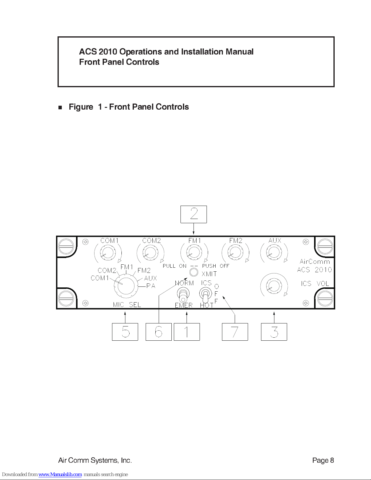
( See Figure 1 Page 8 for pictorial )
n
1 - Norm - Emer Switch
This switch controls the operations of the audio panel in the event of an audio amplifier failure. In the up
position (NORM) the audio panel is in normal operating mode. In the down position (EMER) all audios are
summed and then fed directly to the headphones. This enables the use of the transmitters and other
equipment during audio amplifier failure.
n
2 - QUICK ADJUST Adjustable Receive Audio Volume - On/Off Pots
Any Receive audio can be selected and muted using innovative new QUICK ADJUST volume pots. A
receive audio is selected by pulling out the knob toward the operator. With the receive audio activated, the
headphone volume of the audio can then be adjusted to the desired level. Turning the knob in a clockwise
direction increases the volume level, and turning in the counter-clockwise direction decreases the volume
level. To mute the receive audio, the knob only needs to be pushed back in. The volume for that audio
remains set at the desired level and does not need to be reset the next time it is selected.
n
3 - ICS Volume Control
This knob adjusts ICS headphone volume. Clockwise rotation increases the volume - counter clockwise
rotation decreases the volume.
n
4 - Lighting
The audio panel is lit by two 28V lamps ( P/N 327 ) which provide night time visibility for all panel legends.
These lamps can be replaced in the event of a failure by unscrewing the front panel mounted filter cap,
inserting a new lamp, and reinserting the filter into the front panel.