Varimixer V30K Guide

SPARE PARTAND OPERATION MANUAL
FOOD MIXER Model V30K
Dec. 2018
Version Machine no. Part Page
102018 Round 30006732 Bowl Accessories

2
Caution -READ BEFORE OPERATING- Caution
Varimixer recommends that mixer operators be at least 18 years of age and be thoroughly trained
on the use of the mixer.
Varimixer recommends that the following precautions be adopted to help make the mixer operation
safer and more efficient.
........- All operators should be at least 18 years of age.
- All operators should be thoroughly trained before being allowed to operate the mixer.
- NEVER reach into the bowl when the mixer is running.
- Do not wear loose clothing or rings while operating the mixer.
- Stop the mixer and lower the bowl before adding ingredients, scraping the bowl, removing the
............agitator, or removing the product.
- Stop the mixer before removing or installing attachments into the drive hub.
- Do not attempt to assemble or disassemble attachments while mounted into the drive hub.
- Always use the pusher plate with the slicer/meat grinder attachments.
- NEVER bypass the safety mechanisms supplied on the mixer. Doing so can cause injury and
............is the responsibility of the user to insure these safety mechanisms are operating properly.

3
LIMITED WARRANTY
Varimixer warrants its commercial mixers to the original purchaser against defects in material or manufacture for a period of one year
from the date of original purchase, subject to the following exclusions and limitations. The warranties provided by Varimixer do not ap-
ply in the following instances:
EXCLUSIONS
1. In the event that the equipment is improperly installed. Proper installation is the responsibility of the installer, proper installation pro-
cedures are covered in the Varimixer Spare Parts and Operations Manual.
2. In the event that the equipment is improperly maintained. Proper maintenance is the responsibility of the user. Proper maintenance
procedures are covered in the Varimixer Spare Parts and Operations Manual.
3. In the event that failure or malfunction of the appliance or any part thereof is caused by abnormal use or is otherwise not attribut-
able to a defect in material or manufacture.
4. In the event that the appliance , by whatever cause, has been materially altered from the condition in which it left the factory.
6. On parts which would normally be worn or replaced under normal conditions.
7. With regard to adjustments and/or calibrations. Checking of and changes in adjustments and calibrations are the responsibility of
the installer, Proper installation is the responsibility of the installer, proper installation procedures are covered in the Varimixer Spare
Parts and Operations Manual.
If any oral statements have been made regarding the appliance, such statements do not constitute warranties and are not part of the
contract of sale. This Limited Warranty constitutes the complete, final and exclusive statement with regard to warranties.
.
THIS LIMITED WARRANTY IS EXCLUSIVE AND IS IN LIEU OFALL OTHER WARRANTIES WHETHER..WRITTEN,
ORAL OR IMPLIED, INCLUDING, BUT NOT LIMITED TO,ANY WARRANTY OF..MERCHANTABILITY OR FITNESS FOR
PARTICULAR PURPOSE OR WARRANTYAGAINST LATENT..DEFECTS.
LIMITATIONS OF LIABILITY
In the event of warranty claim or otherwise, the sole obligation of Varimixer shall be the repair and/or replacement at the option of Vari-
mixer, of the appliance or component or part thereof Such repair or replacement shall be the expense of Varimixer except that travel
over 100 miles or two hours, overtime, and holiday charges shall be,, the expense of the purchaser. Any repair or replacement under
this warranty does not constitute an extension of the origin, warranty for any period for the appliance or for any component part thereof.
Parts to be replaced under this warranty will be repaired or replaced at the option of Varimixer with new or functionally operative parts.
The liability of Varimixer on any claim of any kind, including claims based on warranty, expressed or implied, contract, negligence, strict
liability or any other theories shall be solely and exclusively the repair or replacement of the product as stated herein, an such liability
shall not include, and purchaser specically renounces any rights to recover, special, incidental, consequential or other damages of any
kind whatsoever, including, but not limited to, injuries to persons or damage to property, loss of prots or anticipated prots, or loss of
use of the product.
TO SECURE WARRANTY SERVICE
If you claim a defect covered by this Limited Warranty, rst direct your claim to the local Authorized Service Agency, giving model, serial
and code numbers, voltage, a description of the problem and your sales slip. If this procedure fails to be satisfactory to you, you may
write to the Varimixer National Service Manager, 14240 South Lakes Drive, Charlotte, NC 28273; you should include the information
listed above.

4
General:
This manual should be seen as an integral part of the mixer and should be kept by the machine throughout its working life.
Beforethemachineiscommissioned,itisimportanttoreadtheseinstructionsthoroughly, particularly the section on user safety
.
The manufacturer may update the product manual without updating this copy of the manual.
The manufacturer will not be liable for faults caused by:
• Careless, improper or incorrect use of the mixer
• Non-standard use (not for the purposes described in the manual)
• Incorrect installation
• Incorrect power supply to the machine
• Failure to comply with maintenance instructions
• Modications to the machine
• Spare parts and accessories that are not original or specied for this model
• Failure to comply with instructions in this manual
In case of faults with the mixer, please contact the Lokal Authorized Service Agency.
UnpackinG:
The machine should be unpacked and the packaging disposed of according to regulations applicable in the country concerned.
Before the mixer is removed from the pallet, check that all parts are present with the machine:
• Bowl Screen, Power cable, 32 mm xed spanner for legs, Bowl trolley
• Bowl, Whip, Beater, Hook and Scraper with blade, if these were selected with the order.
The machine can be released from the pallet by cutting the strips.
contents:
General: ............................................................................................................................................................4
UnpackinG: ............................................................................................................................................................ 5
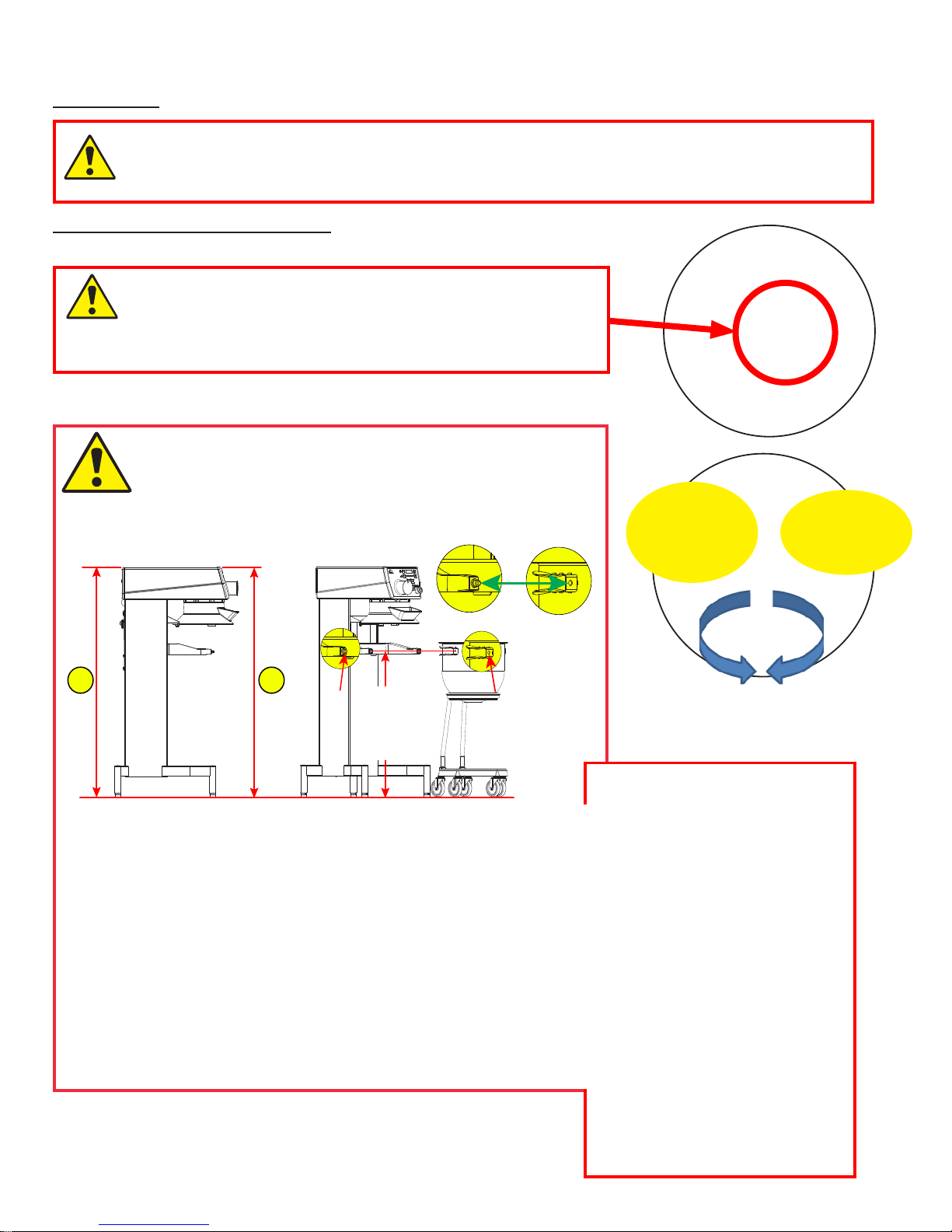
transport: ............................................................................................................................................................5
installation and adjUstments: ..............................................................................................................................5
commissioninG:.......................................................................................................................................................6
recommended Use of the machine:.......................................................................................................................... 6
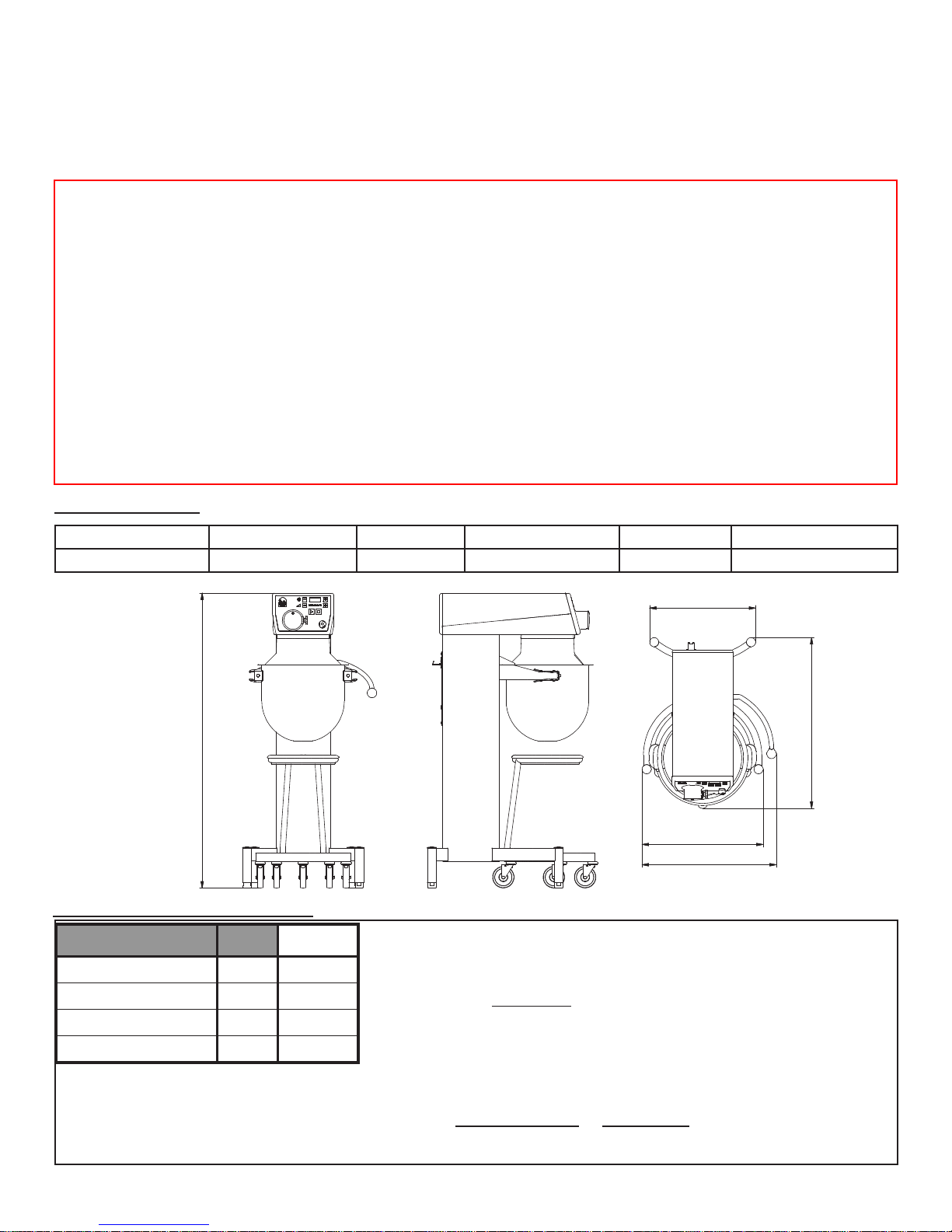
technical data: .....................................................................................................................................................6
max. capacity of the machine: ................................................................................................................................6
components of the machine: .................................................................................................................................. 7
safety: ............................................................................................................................................................8
adjUstments:.........................................................................................................................................................8
kodiak User-friendliness: ..................................................................................................................................9
operatinG the mixer:............................................................................................................................................ 10
overloadinG:....................................................................................................................................................... 11
procedUre in case of overloadinG:...................................................................................................................... 11
recommended max. speeds: .................................................................................................................................. 11
recommended max. speeds for attachment drive: ................................................................................................. 11
correct Use of tools:......................................................................................................................................... 11
cleaninG: .......................................................................................................................................................... 11
lUbrication and Grease types: ............................................................................................................................. 11
attachment drive:................................................................................................................................................ 11
display of mixer data ........................................................................................................................................... 12
error codes and possible solUtions:...................................................................................................................12
access to the fUse:.............................................................................................................................................13
example electrical connections:......................................................................................................................... 13
circUit diaGram: ..................................................................................................................................................14
mixer spare parts ................................................................................................................................................16

5
transport:
Lifting equipment should always be used to move the machine.
The machine must not be pulled or lifted by the bowl lift handle.
When the machine is moved, it should be in a vertical position at all times.
installation and adjUstments:
The ambient temperature around the machine must not exceed 113o F.
When the mixer is delivered, the adjustable feet will be turned right to the
bottom. The height of the legs should be adjusted so that the bowl on
the bowl trolley ts perfectly into the bowl arms.
The bowl arms should be at the correct height above the oor before
the machine is taken into use – see Adjustments.
Adjustments:
Together with the mixer
comes a 32 mm fixed
spanner to be used for
adjustments.
To raise leg
turn
clockwise
To lower leg
turn
anticlockwise
It is of the outmost importance that the legs of the machine are
adjusted so that the conditions in the following sketch are met.
Condition 1:
The top of the mixer must be parallel to the oor. To ensure this you must measure
the distance from the top of the machine to the oor:
The dimension must be the same when measured at the front of the mixer
and at the rear of the mixer:
Condition 2
The mixer must be height adjusted so that the bowl on the bowl trolley ts exactly
in the bowl arms:
Basically, the dimension from oor to centre of the knobs on the bowl arms must
be 34 1/16”. If the bowl on the bowl trolley does not t exactly in the bowl arms
at this dimension, adjust slightly on the front legs of the mixer.
12
86,5cm

6
Electrical connection:
Users can connect the mixer to the power supply themselves; refer to the section on Electrical connection which must be followed.
For the benet of service staff, it should be clear to see when the mains plug to the mixer has been removed from the socket in the wall
.
The cable is xed to the machine in the plug made of silicone, see “Components of the machine” page 8
Before the machine is connected to the mains, check that the voltage and frequency printed on the name plate
are correct for the installation location. The name plate is positioned uppermost on the back of the machine.
There is a risk of injury if the machine is not earthed.
It must be ensured that the cable used to connect the machine to the mains meets the standard for the country in which
the machine is installed. See also Example electrical connections, page 13
The mixer must be earthed. Failure to do so may cause injury. If there is no earth connection, the EMC lter will not
work, with the risk of damage to the frequency converter.
When the machine is connected, phase + neutral + earth or phase + phase + earth should be used. In both cases, it
is important to ensure that the voltage between the two live pins matches the name plate.(See examples on page 13)
The machine must only be connected to an earthed mains supply.
Aplug with two pins plus earth should be used.Alternatively, two wires plus earth from a three-phase supply may be used.
The machine should be protected by a differential switch.
The machine is protected by a 10A fuse. The fuse is built into the socket on the back of the machine.
53 13/16”
24 9/16”
22 1/8”
19 7/16”
31 3/16”
technical data:
Gross weight Net weight HP Volts Amps Variable speed, tool
319.7 lbs 253.5 lbs 1.6 115V, 208V, 230V 4.4A 64 – 353 rpm
max. capacity of the machine:
AR = absorption ratio (%AR)
(liquid as % of dry matter)
E.g. a basic recipe includes 2.2 lbs dry matter and 1.3 lbs liquid:
this gives AR = 1.3 lbs x 100 = 60%
2.2 lbs
If, for example, the maximum capacity of the mixer is required, the calculated AR =
60% is used to determine the amount of dry matter and liquid in the dough:
Maximum capacity of the machine = 28.7 lbs for dough with AR = 60%
Now the weight of the dry matter in this dough is calculated as follows:
Dry matter = max. capacity x 100 = 28.7 lbs x 100 = 17.9 lbs
AR + 100 60 + 100
Weight of liquid = 28.7 lbs - 17.9 lbs = 10.8 lbs
Capacity per mix Tool KODIAK
Egg white Whip 3.17 Qts
Mayonnaise Whip 21.13 Qts
Yeast dough (60% AR) Hook 28.7 lbs
Meatball mix Beater 44.1 lbs
Local variations in the quality of the raw materials may
affect water absorption, volume, baking characteristics
etc., and hence capacity.

7
commissioninG:
Bowl, tools and Bowl Screen should be cleaned before use – see section on Cleaning, page 11.
The bowl arms should be at the correct height above the oor before the machine is taken into use – see Adjustments, page 5.
recommended Use of the machine:
The machine is designed for the manufacture of products that do not trigger any reactions or release substances
that may be harmful to the user when in use.
The machine must not be used in an explosive atmosphere.
The mixer must only be operated by staff who have been trained in the use of the machine according to these
instructions. Users must be over 18 years of age.
The mixer is designed for commercial use in kitchens, catering outlets and bakeries.
The machine may only be used as specied in this manual.
Only bowls designed for Kodiak 30 may be used.
Tools should be used in conjunction with the corresponding bowl – a 30 Q tool
with the 30 Q bowl and a 30/15 Q tool with the 30/15 Q bowl
Unless the change is recommended by the manufacturer, modifying the machine is prohibited.
If the machine is tted with an attachment drive, only accessories produced or recommended by manufacturer should be attached.
safety:
The machine is designed for the manufacture of products that do not trigger any reactions or release substances
that may be harmful to the user when in use.
Users must be over 18 years of age and trained in the use of the machine according to these instructions.
User safety is assured as follows:
• Tools can only rotate when the bowl screen is in place and the bowl is lifted.
• The bowl screen is made of plastic. It is not possible to attach the guard incorrectly.
• No access to rotating tools.
• The spread of our dust is inhibited.
• Equipped with emergency stop - The tool stops rotating in less than 4 seconds (also for normal shut-down and stop via
bowl screen).
• Clearance between guard/stand and lifting handle at least 1 31/32”.
• Noise level under 70 dB.
• Machine remains stable on a slope of up to 10o.The distance from the oor to the bowl arm should be adjusted as shown
in the section on Adjustments, page 5.
The machine is protected against overvoltage.
Non-ionising radiation is not produced intentionally, but rather technically conditioned by electrical equipment (e.g. electric mo-
tors, live power lines or solenoids). The machine is not equipped with strong permanent magnets. By maintaining a safe dis-
tance (between the eld source and implant) of 11 13/16”, any impact on active implants (e.g. pacemakers, debrillators) can
likely be prevented.
The machine should be positioned to allow space for normal use and maintenance.
Good ergonomics for the user is ensured by the accompanying bowl trolley, which eliminates heavy lifting of the bowl and
maintains the right working height.
The following recommendations apply to work with powdery ingredients:
• Powdery ingredients should not be poured into the bowl from a great height.
• Bags of e.g. our should be opened at the bottom, down in the bowl.
• Do not run up to the maximum speed too quickly.
There is a risk of injury if the machine is not earthed.
It must be ensured that the cable used to connect the machine to the mains meets the standard for the country
in which the machine is installed. See also ‘Electrical Connection’.
Placing your hands in the bowl while the machine is running may cause physical injury.

8
Socket on the back of the ma-
chine; contains 10A fuse, see
page 13.
Lifting handle
Bowl truck
Bowl
Control panel
Bowl Screen
Mixer head
Adjustable legs; see
page 5 for adjustment
Mixer tool
Bowl arms; see page 5
for attachment between
bowl arms and bowl
Standard equipment, as follows:
• Bowl trolley
• Bowl – 30 Qt
• Hook,beaterandwhip for30Qtbowl
Optional accessories
• Scraper for 30 Qt bowl, if mixer is
tted for a scraper
• Bowl – 15 Qt
• Hook,beaterandwhip for15Qtbowl
• Scraper for 15 Qt bowl, if mixer is
tted for a scraper
Control panelwith
attachment drive
components of the machine:

9
kodiak User-friendliness:
KODIAK has been designed in partnership with kitchen and bakery staff, which has resulted in a number of user benets:
The machine itself
Can be connected to the mains by the user
Is made of stainless steel
Has height-adjustable feet to ensure that the high bowl trolley works properly
Is easy to clean, with large surfaces and a removable safety guard which can be machine-washed
The power cord is connected to a waterproof silicone plug and can not be shaken from the machine
The inclined control panel combined with the large bowl diameter provides a good view of the contents of the bowl.
The machine is equipped with a spring that helps to lift and lower the bowl
Control panel:
The control panel is simple and intuitive, with large push buttons.
The speed can be increased/decreased continuously by holding down and . It is also possible to ‘step’ between the
predened speeds
The panel is inclined at the ergonomically correct height, making it very comfortable to use.
The panel is easy to clean with a damp cloth.
There is a built-in timer function with a display, which can also be used to show the
number of operating hours.
Bowl screen:
Theone-piecebowlscreen is made oftransparentplastic.The screeniseasytoremove
and clean. The screen can be machine-washed at up to 140oFand can withstand up
to 194oF for short periods (Max 20 sec.)
The screen is made of a special impact-resistant material which can withstand daily
use in a commercial kitchen.
The bowl screen is held in place by magnets, so there are no loose parts that can break
or collect dirt.
It is not possible to attach the screen incorrectly.
A force corresponding to 6.6 lbs or 30 N should be used to remove the screen.
The lling hole in the bowl screen can be turned to suit the user’s needs.
Bowl and bowl trolley:
The bowl is not very deep but has a large diameter, which makes it easier to see the
contents while working.
The bowl does not have to be lifted into place in the bowl arms, but can be wheeled
directly into position.
The bowl trolley is used for transfer from mixer to workbench, dishwasher, stores etc.
The bowl trolley provides an ergonomically correct working height.
The bowl trolley spares the user any heavy lifting.
The bowl can be tilted in the rubber ring on the bowl trolley.
Tools:
Themixerwhipisverycompact in design, which providesforalongservicelife. It must be handled accordingtotheseinstructions.
The beater and hook are made of stainless steel.

10
Before starting the machine:
Place the bowl in the bowl trolley.
Put the desired tool into the bowl and wheel it into position bet-
ween the bowl arms. Ensure that the bowl is correctly engaged
with the bowl arms; see Adjustments, page 5.
Fit the bowl screen and turn it so the lling hole is accessible
when the machine is running.
Turn the tool to lock it into the bayonet tting.
Lift the bowl with the aid of the lifting handle.
The mixer is now ready to start.
It is possible to set both the running time and speed before
starting the machine; see next section:
Start the machine:
Press to start the mixer.
Press next to to increase the speed.
Press next to to reduce the speed.
The speed is shown as a number on the scale .
The display 1represents the lowest speed, ap-
prox. 64 rpm.
The display 12345678represents the highest speed, ap-
prox. 353 rpm.
If a specic start speed is wanted, you set the speed and then
start the mixer by pressing .
Display of running time – Timer function:
Select a running time for the mixer by pressing next to .
The running time is shown in minutes and seconds in the timer
eld between and .
Running times of up to 90 minutes are available.
The running time will not be reset if is pressed once; press
once more and it will be reset.
If no running time is selected, the display will show the time
elapsed since the mixer was started.
If the time set on the timer runs out while the mixer is running,
the mixer stops and you hear a bib.
Inspection of ingredients while in use:
If the mixer needs to be stopped temporarily without affecting
the running time, press . The mixer will slow down and then
stop and the running time will stop too.
The bowl can now be lowered and the ingredients checked.
Lift the bowl and press , and the mixer will start and the run-
ning time will resume.
Stop the machine:
To stop the machine:
• Press . Running time not reset.
• Press twice. Running time reset.
• Press the emergency stop - the running time will be reset.
• ‘Tilt’ the bowl screen - the running time will be reset.
• Lower the bowl - the running time will be reset.
In all cases the mixer can be restarted by pressing .
It will start at the lowest speed.
operatinG the mixer:
Emergency stop
Stop
Increase time
Timer (timer eld)
Decrease time
Speed indicator
Decrease speed Increase speed
Start

11
12345678
12345678
12345678
XXXXX
XXX
12345678
12345678
XXXX
overloadinG:
The mixer must not be overloaded.
Possible overload situations:
• Workingwithexcessivelytoughandheavydough
• Mixer tool exceeding the recommended speed
• Wrong mixer tool being used.
Larger lumps of fat or chilled ingredients must be reduced
before they are placed in the bowl.
Overloading will cause the frequency converter to stop the
machine.
, or will be displayed in the timer
eld.
Follow the description under “Procedure in case of over-
loading”.
procedUre in case of overloadinG:
Spot the error code in the section “Error codes and possible
solutions”, page 13 and follow the suggestion for a solution.
When done, remove the error code by pressing .
The mixer can now be restarted by pressing .
recommended speeds:
correct Use of tools:
Recommended uses of tool:
The whip should not be struck against hard objects
such as the edge of the bowl. This will shorten the
life of the tool because of increasing deformation.
To make mashed potato, use the beater and then
the standard whip.
cleaninG:
Themachinemayonlybecleanedbytrainedstaff
over 18 years of age.
Themachineshould becleaneddailyafteruse.Itshould bewiped
with a soft brush and clean water. Sulphonated soaps should be
used with care, as they destroy the lubricants in the machine.
The machine should never be rinsed with a hose.
Themachinepartsmadeofaluminium, bowl armsand
bowl trolley, must not be washed with very alkaline
cleaning agents (pH must be between 5.0 and 8.0).
Please note that the plastic safety guard may be
damaged if it is exposed to high temperatures for
a prolonged period. (Max. temperature 140
o
F)
The lling chute is dishwasher-safe
The soap suppliers may be able to help by recommending the
right type of soap.
lUbrication and Grease types:
Lubrication and other servicing may only be carried
out by trained staff over 18 years of age.
The lid of the mixer may only be removed when the
cable to the mains supply has been removed.
When repairs are made to the mixer head, the gear wheel and
internal gear should be lubricated with Molykote G-1502 the
needle bearings in the mixer head can also be lubricated with
this type of grease.
If the machine is supplied with an attachment drive, the gear
for the attachment drive should be lubricated with Statoil
GreaseWay LiCa 80.
Do not use any other grease types than those specied above.
attachment drive:
The machine may be tted with an attachment drive into
which optional accessories, such as meat mincers and veg-
etable cutters, can be attached.
For further information on the assembly and use of optional acces-
sories, please refer to the manual that comes with the accessory.
Themachinemustbe shutdownwhentheaccessory
is tted to the attachment drive.
recommended speeds for attachment drive:
Whip Beater Hook
Cream Cake mix Bread dough
Egg whites Buttercream Rye bread
Mayonnaise Wafe mix etc.
etc. Forcemeat
etc.

12
Part Action Frequency Note
Bowl screen Check the safety of the bowl screen:
Does the tool stop rotating when the
screen is tilted/removed?
Regularly If the tool does not immediately
stop rotating on tilting/removal of
the screen, the machine must not
be used.
Call the engineer
Emergency stop Test theemergencystop:Doesthe tool
stoprotatingwhen theemergencystop
is activated?
Regularly
If the tool does not immedia-
tely stop rotating on activation of the
emergency stop, the machine must
not be used.
Call the engineer
Mixer head The mixer head should only be lubri-
cated on repair, see the section “Lub-
rication and grease types”.
During repairs
The machine’s
other moving
parts
The moving parts that belong to the
bowl’s lifting mechanism all run in
maintenance-free plain bearings and
should not therefore be lubricated.
Never
Attachmentdrive Therubber plug forcoveringtheopen-
ing of the attachment drive should be
on the machine and be intact.
Daily The rubber plug must cover the
opening on the attachment drive
when the latter is not in use.
Cleaning Follow the instructions in the section
“Cleaning” Follow the instructions
in the section “Cleaning”
systematic maintenance:
readinG the machines data:
Press the stop button for 5 sec. The machine’s data will then be displayed as alternating text in the display. There are ve
readings corresponding to the ve data sets described below:
• Data set 1: States rmware version, displayed as “F” followed by three gures, e.g. = rmware version 3.
• Data set 2: States the machine’s running time, displayed as “t” followed by three gures, which indicate the number of
9.999-minute cycles, e.g. = 2 x 9.999 min., or 19.998 min.
• Data set 3: Displays four gures, which indicate the number of minutes the current cycle has been running, e.g. =
1.234 min.I.e., if is displayed followed by , the machine has been running for 19.998 min. + 1.234 min.,
or a total running time of 21.232 min.
• Data set 4: States the number of times the machine has been disconnected from the power supply (plug pulled out of the
machine/powercut/switched off) and restarted, displayed as “r” followed by three gures, which indicate the number of restarts,
e.g. = 2 x 9,999 restarts, or 19,998 restarts.
• Data set 5: Displays four gures, which indicate the number of restarts which have happened in the current cycle, e.g.
= 1234 times. In other words, if is displayed followed by , the machine has restarted a total of 19,998 +
1,234 times, or 21,232 times.
readinG the error loG:
It is possible to display a log of the errors that have occurred:
• Hit emergency stop and press next to .
• The display shows the latest error rst.
• To scroll back through the errors, press next to ; to scroll forward, press next to .
• The last eight errors can be displayed.
• Deactivate emergency stop to cancel the display

13
error codes and possible solUtions:
For some errors, the control system will show an error code in the display:
User pressed without raising the bowl to working height.
Solution: Raise bowl to working height.
User pressed without tting the safety guard.
Solution: Fit the bowl screen.
The Thermal sensor in the motor has overheated.
Solution: The error will disappear when the temperature has dropped to an acceptable level.
Stop the mixer and reduce the quantity of ingredients in the bowl. When it starts again, select a lower speed.
There is an error in communication between the control panel and the frequency converter.
Solution: Call the engineer.
Error in frequency converter.
Solution: Call the engineer.
Thermal sensor in the frequency converter has cut out.
Solution: The error will disappear when the temperature has dropped to an acceptable level.
Intermittent low voltage in the power supply.
Solution: The power supply to the mixer should be checked by an expert.
Intermittent high voltage in the power supply.
Solution: The power supply to the mixer should be checked by an expert.
The mixer is overloaded - continuously for 50 seconds
Solution: Reduce the quantity in the bowl; alternatively, the product may need to be divided into smaller parts or diluted before
the machine is restarted. When restarted, select a lower speed, if speed was the problem
The error code is removed by pressing
The mixer is overloaded - momentarily (overloaded 8 times within 20 seconds
Solution: Reduce the quantity in the bowl; alternatively, the product may need to be divided into smaller parts or diluted before
the machine is restarted. When restarted, select a lower speed, if speed was the problem.
The error code is removed by pressing
Blockage.
Solution: Remove the object that caused the blockage.
The error code is removed by pressing
, and can also occur when using the attachment drive.
access to the fUse:
If the fuse burns out, it can be replaced without the aid of technical staff.
• The fuse is located in the socket on the back of the machine.
• Be sure to remove the power cord before changing the fuse
example electrical connections:
Local 50/60 Hz supply. Name plate
Power supply:
phases x voltage With
neutral Earth Voltage Phases Use
neutral Use
earth
Note that the machine must not be connected
without earth, as this may compromise the action
of the EMC lter by removing the discharge to
the ground, and may be dangerous for the user.
For functional and safety
reasons, the machine must
be connected to the earth.
1 x 115V +/- 10% Neutral yes 115V 1 yes yes
1 x 208V +/- 10% Neutral yes 208V 1 yes yes
1 x 230V +/- 10% Neutral yes 230V 1 yes yes

14
A/S WODSCHOW & CO
Kirkebjerg Søpark 6
DK-2605 Brøndby, Denmark
www.bearvarimixer.dk
Page
Previous page
Next page
Number of pages:
Last printed:
Last corrected:
Page rev.:
Project rev.:
/
Appr. (init/date): /
Const. (project/page):
Drawing no.:
Subject name:Project title:
File name:
Page title: CR30
1
1
CR30
Stelbi
CR30
24-08-2014
01-04-2014
CR30-20140824
Wire code, IEC/EN 60757
PURPLE
230VAC
Power socket
Mixer
MOLEX
Plug
CE
Switch
EM
Emergency Stop
SS
Safety grid Switch
Motor ControlCommunication & Safety
Controller
Motor
Fuse
250V/10A
MOLEX
Plug
Inverter 1,5kW
Inverter box
WR30-552.1M
circUit diaGram:

15
A/S WODSCHOW & CO
Industrisvinget 6
DK-2605 Brøndby, Denmark
www.bearvarimixer.dk
Page
Previous page
Next page
Number of pages:
Last printed:
Last corrected:
Page rev.:
Project rev.:
/Appr. (init/date): /Const. (project/page):
Drawing no.:
Subject name:Project title:
File name:
Page title: CR30 - 230V/ 115V/ 208VAC
1
114-02-2016
14-02-2016
CR30
Stelbi
CR30
CR30-20160214
MIXER
Wire code, IEC/EN 60757
MOLEX
Plug
EM
Emergency Stop
Motor
SS
Safety grid Switch
Motor ControlCommunication & Safety Motor ControlCommunication & Safety
Controller
MOLEX
Plug
230VAC
Powersocket
Mixer
208/115VAC
Powersocket
Mixer
CE
Switch
WR30-552.1M
WR30-552.1M

16
PARTS LIST Material
Name UKName
Part number
QTYITEM Rubber
Micro-V PJ1016-12Micro-V PJ1016-12CR30-9011 DC01 koldreduceret stål
Mounting plate motorMotor pladeCR30-61.3
1
2
Pully ø112 with bushRemskive ø112 med bøsningCR30-129
1
3ST.-Elzink
Hex cap screw M8x16
Sekskantskrue med flange M8x16
STA5751
44 ST.-Elzink
Hex cap screw M6x16
Sekskantskrue med flange M6x16
STA5750105
Pully ø63 with BushRemskive ø63 med bøsning
CR30-12816 DefaultMotpor 1 phaseMotor 1 faset
CR30-8517
3
3
1
5
4
2
7
6
6
ITEM QTY Part number Name UK
11 CR30-90 Micro-V PJ1016-12
21 CR30-61.3 Mounting plate motor
31 CR30-129 Pully ø112 with bush
44 STA5751 Hex cap screw M8x16
510 STA5750 Hex cap screw M6x16
61 CR30-128 Pully ø63 with Bush
71 CR30-85 Motor 1 phase
TRANSMISSION.....................................................................................................................................................16
BOWL SCREEN......................................................................................................................................................17
BOWL ARMS..........................................................................................................................................................17
LIFTING SYSTEM...................................................................................................................................................18
PLANETARY HEAD................................................................................................................................................20
ATTACHMENT HUB ...............................................................................................................................................22
MACHINE COLUMN...............................................................................................................................................24
ELECTRIC-BOX......................................................................................................................................................26
FRONT PANEL.......................................................................................................................................................28
FRONT PANEL, attachment drive ........................................................................................................................30
CABLES..................................................................................................................................................................31
ACCESSORIES ......................................................................................................................................................32
TRANSMISSION
mixer spare parts

17
Part number Name
CR30-23M Bowl arm mounted
with pins
BOWL ARMS
1
CR30-23M
BOWL SCREEN
56CR30P-22
1
Part number Name
56CR30P-22 Removeable plastic
bowl screen

18
ITEM QTY Part number Name Sold as
11 CR30-65.1 Lifting nut CR30-83.1M
21 STA5806 Hexagon nut M10 CR30-83.1M
31 STA2515 Bearing MB2030DU
41 STA6205 Spring cotters for bolt ø2,5
51 CR30-83.1 Lifting bolt CR30-83.1M
62 CR30-68.5 Shaft
74 STA3410 Circlip A25
81 CR30-63M Crankshaft
91 CR30-68.6 Absorber crossbar
10 1 CR30-604 Shock absorber with Cap
11 1 CR30-310 Spring wire
12 1 CR30-62M Lifting arm
13 10 STA5750 Hex cap screw M6x16
14 1 CR30-23M 30L Bowlarm
15 4 STA5697 Socket head screw M3x16
16 1 STA6006 Flatwasher ø10,5-ø20x4
17 1 CR30-62.9 Cover for liftarm
18 2 STA3408 Retainning ring A20
LIFTING SYSTEM

19
A ( 0,30 : 1 )
PARTS LIST Material
Name UKName
Part number
QTY
ITEM 9S20 Automat
Lifting nutLøfte bolt
CR30-65.111 Stainless Steel
Hexagon nut M10
Møtrik M10
STA580612 PTFE- greyBearing MB2030DU
Lejebøsning MB2030DU
STA251513 St.
Spring cotters for bolt ø2,5Fjerdersplit ø2,5
STA620514 ST37-2Lifting boltLøfte boltCR30-83.1
15 SS-W1.4104-slebet h9
Shaft
BøjleakselCR30-68.526 St.
Circlip A25
Seegerring A25STA3410
47 Welded Aluminum-6061Crankshaft
Krumtap arm monteretCR30-63M18 SS-W1.4301-304
Absorber crossbar
Dæmper traversCR30-68.619 St.
Shock absorber with CapOliedæmper med Cap
CR30-604110 Rustfri fjederstål
Spring wire
Fjeder for NSFCR30-310
111
Lifting arm
Løftehåndtag samlet
CR30-62M
1
12 ST.-Elzink
Hex cap screw M6x16
Sekskantskrue med flange M6x16
STA57501013 Alu EN-AA-4410030L Bowlarm Machined30L Bøjle Bearbejdet
CR30-23114 St.
Socket head screw M3x16Cylinder skrue M3x16
STA5697415 PolyamidFlatwasher ø10,5-ø20x4Skive ø10,5-ø20x4
STA6006116 PP-PolypropylenCover for liftarmDækprop for løftearm
CR30-62.9117 St.Retainningring A20Seegerring A20STA3408218
A
13
9
15
10
6
14
7
11
181712
1
2
5
1816
4
3
8
CR30-83.1M

20
PLANETARY HEAD
ITEM QTY Part number Name
11 STA6460 Dowel pin ø8x24-KS4
22 STA3515 Retainning ring J55
31 HK2016 Needel bearing
42 6006 2RS Ballring 6006
52 6206 2RS Ballring 6206
62 STA3518 Retainningring J62
71 R20-235 Axial washer
81 LR17 Bushing
91 STA3470 Circlip SW17
10 1 R20-32 Toothed wheel 1
11 1 R20-31 Toothed wheel
12 1 STA2008 Sha key
13 1 CR30-37 Distance ring f. CR30
14 2 STA3414 Circlip A30
15 1 RN20-1 Toothed wheel - machined
16 1 R15-109 Spring bajonet
17 1 R20-106 Ball 1/4"
18 3 STA5626 Socket head screw M8x30
19 1 CR30-108R Sealing ring G45x52x4
20 1 RN20-272.1 Shawl 20L
21 1 CR30-34 Distance ring
22 4 STA5638 Socket head screw M8x35
23 3 STA6055 Helical springlock washer M8
24 1STA5729 Socket head screw M8x65
25 1 Sold as RN20-3.7Z Main bearing mounted front
26 Sold as CR30-2Z Eccentric head compl.
26A 1 Sold as CR30-2.10Z Eccentric head assy.
26B 1 Sold as CR30-2.11Z Eccentric head assy. prepared for scraper
27 1 Sold as CR30-30.5Z Mainsha assy. for aachment drive
27A 1 Sold as CR30-30.6Z Mainsha assy. not for aachment drive
28 1 Sold as CR30-33Z Bajonet sha assy.
29 1 Sold as CR30-36Z Exentric disc mounted
30 1 Sold as RN20-101Z Needel bearing comppl. BK1816/LR15
31 1 Sold as RN20-101Z Needel bearing comppl. BK1816/LR15
32 1 Sold as RN20-101Z Needel bearing comppl. BK1816/LR15
33 1 Sold as 42CR20-105Z Bajonet for scraber compl
CR30-2M Planetary head compl.
CR30-2.1M Planetary head compl. prepared for scraber
Other manuals for V30K
1
Table of contents
Other Varimixer Mixer manuals

Varimixer
Varimixer TEDDY W5A User manual

Varimixer
Varimixer V150PL Guide

Varimixer
Varimixer V20K Guide

Varimixer
Varimixer RV 10 VL-2 User manual

Varimixer
Varimixer KODIAK20 User manual

Varimixer
Varimixer W20D Guide

Varimixer
Varimixer ERGO100 User manual

Varimixer
Varimixer W20P User manual

Varimixer
Varimixer V20 User manual

Varimixer
Varimixer W40(A) Guide

Varimixer
Varimixer W100PL User manual

Varimixer
Varimixer W20SF User manual

Varimixer
Varimixer W80 Guide

Varimixer
Varimixer V20K Guide

Varimixer
Varimixer RN Series User manual

Varimixer
Varimixer V30K Guide

Varimixer
Varimixer V150PLM User manual

Varimixer
Varimixer V80 Guide

Varimixer
Varimixer W20A Guide

Varimixer
Varimixer W80 User manual