Air Creation NuviX 15 Owner's manual

GDMUNU15-1G Version 0030 2
1 Table of Contents
1Table of Contents................................................................... 2
2Amendment Record Sheet..................................................... 4
2.1 Table of Amendments.......................................................................... 4
2.2 Amendments........................................................................................ 4
3General ................................................................................... 5
3.1 About this Document............................................................................ 5
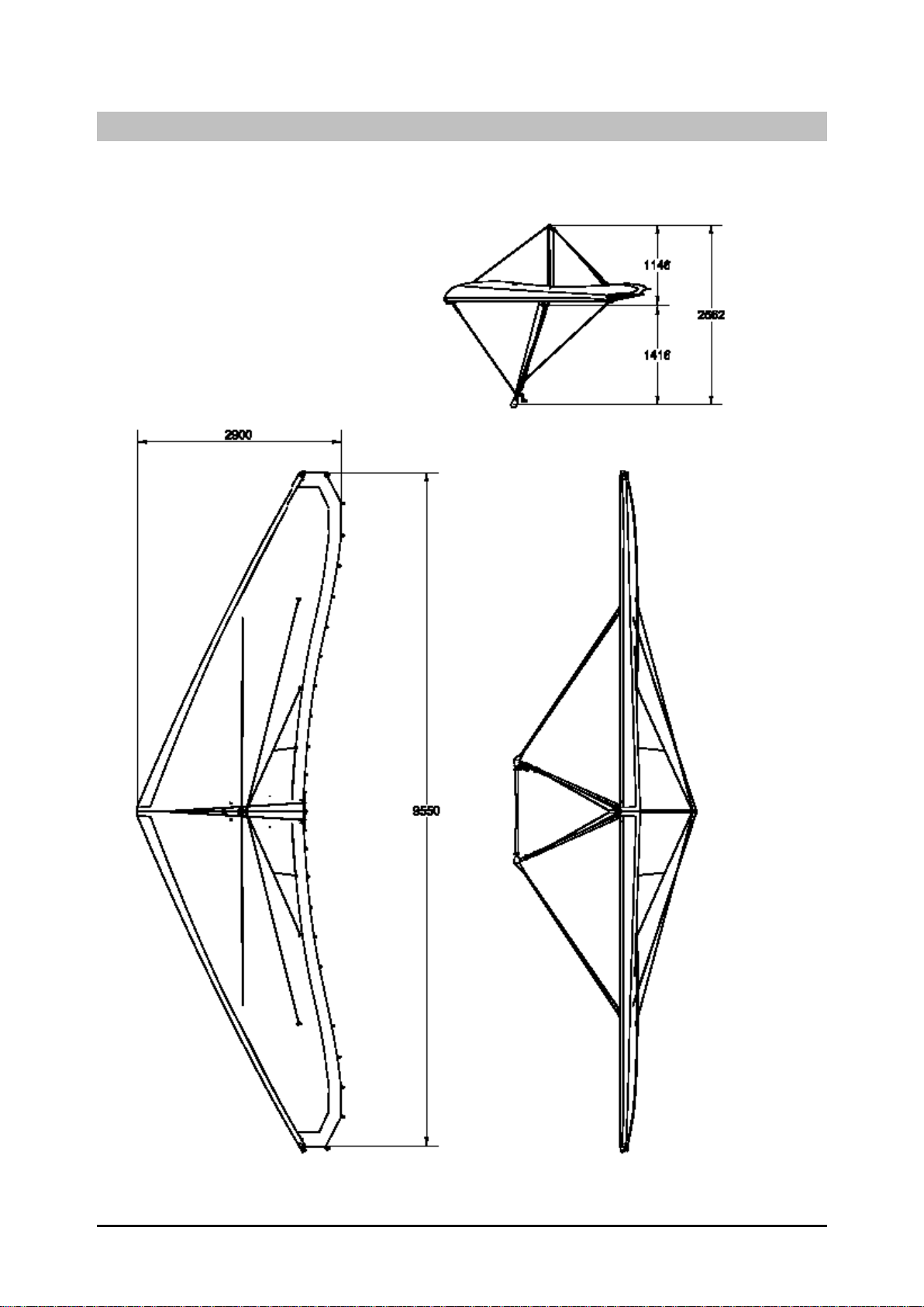
3.2 3-Perspective Diagram......................................................................... 6
Figure 3-1: NuviX in 3 Perspectives..........................................................................................6
4Technical Specifications –Performance.............................. 7
4.1 Technical Specifications....................................................................... 7
4.2 Maximum Added Load / Trikes Adjustment ......................................... 7
4.3 Performance at Maximum Take-Off Weight......................................... 9
5Instructions for Use ............................................................. 10
5.1 Rigging............................................................................................... 10
5.1.1 Assembly..............................................................................................................10
Figure 5-1 : EasyFit Tighteners................................................................................................10
Figure 5-2 : Path of Tensioning Cables ...................................................................................10
5.1.2 Disassembly.........................................................................................................11
5.2 Preflight Check................................................................................... 11
5.3 Flight Specifications........................................................................... 13
5.3.1 Operational Limitations.........................................................................................13
5.3.2 Controls ................................................................................................................13
Figure 5-3 : CORSET Control..................................................................................................15
5.3.3 Flight Techniques .................................................................................................15

GDMUNU15-1G Version 0030 4
2 Amendment Record Sheet
2.1 Table of Amendments
Amendment date
Affected sections
Affected pages
Date inserted
Signature
2.2 Amendments
The information in this manual is based on the data that was available at the time of its
publication. The latest amendments to this manual will be issued on the Air Création
website (http://www.aircreation.fr) in PDF format. This should be printed out and added
to the manual. The amendment table should at that time be updated with the appropriate
details and date. Therefore it is important for operators to check the website regularly for
any amendments that have been made. If any errors or omissions are found in this manual
please advise the factory.

GDMUNU15-1G Version 0030 5
3 General
3.1 About this Document
This manual is a legal document which is approved for use with Air Creation NuviX
wing.
It must be used in conjunction with the particular trike’s operating handbook.
It must remain with the aircraft, and not be amended or altered without authority from Air
Creation.
All pilots should read this manual before flying as pilot in command of the aircraft to
which it refers.
This manual is not intended to teach you how to fly the aircraft. Learning to fly should be
accomplished under the supervision of a suitably qualified flight instructor experienced in
flying this type of aircraft.
What this manual will do is provide the information necessary to a qualified pilot for the
safe flight of this weight shift aircraft.

GDMUNU15-1G Version 0030 6
3.2 3-Perspective Diagram
Figure 3-1: NuviX in 3 Perspectives

GDMUNU15-1G Version 0030 7
4 Technical Specifications –Performance
4.1 Technical Specifications
Area
15.2 sq.m. (163.61 sq.ft.)
Maximum wing loading
30.45 kg/sq.m. (6.2 lbs/sq.ft.)
Airfoil type
Double surface 90%
Span
9.55 m (31.3 ft)
Nose angle
130°
Aspect ratio
6
Empty weight
52 kg (114 lbs)
Ultimate load factors
+ 6g - 3g
Maximum take-off
weight
462 kg (1,019 lbs)
Limit load factors
+ 4g 0g (-2g under gust)
4.2 Maximum Added Load / Trikes Adjustment
The maximum load that may be added under the wing is 411 kg (906 lbs). The following chart
defines the useful load of our various trike models with the NuviX 15 wing.
Trike
Lst
Skypper
700E
Lst
Skypper
582 / 582S
Lst
Skypper
912 (S)
TANARG
582
TANARG
912
TANARG
912 S (ES)
MTOW with
parachute**
450 kg
462 kg
462 kg
462 kg
462 kg
462 kg
992 lbs
1019 lbs
1019 lbs
1019 lbs
1019 lbs
1019 lbs
MTOW w/o
parachute
450 kg
450 kg
450 kg
450 kg
450 kg
450 kg
992 lbs
992 lbs
992 lbs
992 lbs
992 lbs
992 lbs
Empty weight *
203 kg
199 kg
220 kg
(222 kg)
219 kg
238 kg
240 kg
(235 kg)
448 lbs
439 lbs
485 lbs
(489 lbs)
483 lbs
525 lbs
529 lbs (518
lbs)
Useful load *
247 kg
251 kg
230 kg
(238 kg)
231 kg
212 kg
210 kg (215
kg)
545 lbs
553 lbs
507 lbs
(525 lbs)
509 lbs
467 lbs
463 lbs (474
lbs)
* optional equipment excluded ** French regulations

GDMUNU15-1G Version 0030 8
Caution: fitting of any equipment or any other change should never lead to
exceeding the maximum empty weight value mentioned above, according to security
standards and aircraft conformity.
It is possible to adapt other trikes than the ones mentioned above. Their maximum weight
should be less than 411 kg (906 lbs) fully loaded. The stability of the trike alone must
be absolutely positive in yaw in order to guarantee the stability at high speed.
Then progressive tests will be performed to check the adaptation wing/trike, especially
concerning the position of the control bar and the thrust line height. The necessary engine
power for safe two-seater flight should be at least 60 HP. Check during fitting whether
the trike propeller stays clear of the lower rear longitudinal cables and the keel. A
minimum clearance of 10 cm (4 inches) should be respected when the hang
point is set to the front position and the wing is fully nose up and all the way
banked on one side.

GDMUNU15-1G Version 0030 9
4.3 Performance at Maximum Take-Off Weight
Trike
Lst
Skypper
700E
Lst Skypper
582 / 582S
Lst
Skypper
912 (S)
TANARG
582
TANARG
912
TANARG
912 S (ES)
Maximum weight
450 kg
462 kg
462 kg
462 kg
462 kg
462 kg
992 lbs
1019 lbs
1019 lbs
1019 lbs
1019 lbs
1019 lbs
Stall speed
60 km/h
61 km/h
61 km/h
61 km/h
61 km/h
61 km/h
37 mph
38 mph
38 mph
38 mph
38 mph
38 mph
Minimum speed
63 km/h
64 km/h
64 km/h
64 km/h
64 km/h
64 km/h
39 mph
40 mph
40 mph
40 mph
40 mph
40 mph
Recommended
climbing speed
80 km/h
80 km/h
80 km/h
80 km/h
80 km/h
80 km/h
50 mph
50 mph
50 mph
50 mph
50 mph
50 mph
Take-off run
115 m
100 m
90 m (80 m)
100 m
90 m
80 m (85 m)
377 ft
328 ft
295 ft
(263 ft)
328 ft
295 ft
263 ft
(279 ft)
50 ft clearing distance
250 m
225 m
210 m
(180 m)
225 m
210 m
180 m
(190 m)
820 ft
738 ft
689 ft
(591 ft)
738 ft
689 ft
591 ft
(623 ft)
Climb rate
2.7 m/s
3.4 m/s
4.7 m/s
(5.7 m/s)
3.4 m/s
4.7 m/s
5.7 m/s
(5.1 m/s)
532 ft/min
669 ft/min
925 ft/min
(1122 ft/min)
669 ft/min
925 ft/min
1122 ft/min
(1004 ft/min)
Recommended
approach speed
85 km/h
85 km/h
85 km/h
85 km/h
85 km/h
85 km/h
53 mph
53 mph
53 mph
53 mph
53 mph
53 mph
Landing distance from
50 ft height
145 m
150 m
150 m
150 m
150 m
150 m
476 ft
492 ft
492 ft
492 ft
492 ft
492 ft
Max L/D ratio
8.5
8.5
8.5
9
9
9
Max glide ratio speed
80 km/h
80 km/h
80 km/h
80 km/h
80 km/h
80 km/h
50 mph
50 mph
50 mph
50 mph
50 mph
50 mph
Side wind limits
15 kts
15 kts
15 kts
15 kts
15 kts
15 kts
V.N.E. (velocity never
to exceed)
165 km/h
165 km/h
165 km/h
165 km/h
165 km/h
165 km/h
103 mph
103 mph
103 mph
103 mph
103 mph
103 mph
V.man (never to be
exceeded in very
turbulent air)
120 km/h
122 km/h
122 km/h
122 km/h
122 km/h
122 km/h
75 mph
76 mph
76 mph
76 mph
76 mph
76 mph
Roll rate at 120% V
min. (45°/45°)
3 s
3 s
3 s
3 s
3 s
3 s

GDMUNU15-1G Version 0030 10
5 Instructions for Use
5.1 Rigging
5.1.1 Assembly
1. Open the wing bag, make sure that the A-frame is on top, and remove fastenings and paddings.
2. Assemble the A-frame with the push-pin. Cables must not pass through the inside.
3. Lift the wing from the front and rotate it so that the wing is laying with the assembled control
frame flat on the ground. Carefully open the two half wings to their maximum extent.
4. Slip the tensioning handle behind the foot of the king post taking care to pass the cables
under the front central strap that links the two nose battens in front of the king
post foot (Figure 5-2).
5. Fit the king post plastic head at the top of the king post without entangling pitch lines.
6. Fit the king post onto its locating lug on the keel, between the two tensioning cables, taking care
not to cross them and not to pinch the flexible neoprene central link.
7. Carefully slide the upper sail bent battens in their respective pockets and tension the sail by
fastening the Easyfit tighteners (Figure 5-1).
Figure 5-1 : EasyFit Tighteners
Figure 5-2 : Path of Tensioning Cables
8. Pull the cross tube swan catch tensioner towards the trailing edge, inside the triangle formed by the
retaining strap of the central battens on the keel behind the king post and under the pulleys blocks
of the CORSET, then hook it to the rail screw at the keel tip (Figure 5-2). To ease the operation,
carefully center the A-frame, ensure that the tabs and heat shrink coverings of the lower lateral
cables do not get stuck in the sail opening at the cross tube/leading edge connection and that the
stainless steel tabs line up with the control bar.
9. Pull down the swan catch tension lever and fix it in the rail with the pushpin.
10. Raise the nose of the wing and lift it on its A-frame. To avoid dragging the tips of the wing on the
ground, it is recommended that a second person hold the back of the keel.

GDMUNU15-1G Version 0030 11
11. Fix the front lower longitudinal cables in the rail under the nose plate with the help of the swan
catch tension lever and the pushpin.
12. Carefully slide the lower sail battens in their pockets and secure them within the triangular
openings.
13. Place the two straight battens of the wing tips on the plastic lug attached to the tube of the leading
edge, and tighten the upper surface with the clasps.
14. Close the two zippers of the neoprene central link. Insert the trailing edge tensioning batten in the
nylon slots at the ends of the two central battens by pulling back.
15. When connecting the trike, slip the security fastening cable behind the kingpost, then through the
loop in the security strap aligned with the front of the kingpost, behind the kingpost again, and then
fix it to the beam of the trike. The security cable should pass under the tensioning cables and
between the fine cord of the CORSET and the keel. This operation secures the trike as well as
fastening the crossbar tensioning system.
16. Assemble the nose cone by means of the Velcro strips (see 5.3.1).
For the final stage of lifting the wing on the trike, follow the instructions in the trike
operating handbook.
5.1.2 Disassembly
Dismantling is carried out in reverse order of the assembling operations. The CORSET
must imperatively be loose (set in the “slow” position) before dismantling.
Before setting the wing flat on the ground, insert the protective padding on the
keel over the hang point bracket and on the right A-frame strut over the guides of the fine
cord of the CORSET in order to avoid damaging the sail with these jutting parts.
Before folding up the two half-wings,place the leather cap on the tensioning
device lever and slip it inside the sail at the front of the kingpost foot to avoid tearing
any part of the sail or the frame while closing the leading edges.
Never release the tension of the wing without first removing the battens of the wing
tips which rest on the leading edges.
5.2 Preflight Check
The wing preflight check will be easier if made before lifting the wing above the trike. The
following is a brief summary of the minimum pre-flight inspection, which assumes that the
scheduled maintenance checks outlined in the maintenance manual has been performed. If you
are unsure, it does no harm to increase the number of items in your inspection in accordance with
the recommendations of the maintenance manual.

GDMUNU15-1G Version 0030 12
1. Position the wing horizontally once coupled with the trike.
2. Visually check the symmetry of the two leading edges.
3. Check noses plates assembly, bolts, nuts, thimbles and Nicopress of the front lower longitudinal cables,
swan catch correctly positioned, pushpin and wires attached.
4. Slide your hand along the leading edges to check for possible damage. Make sure the profile of the
upper surface of the leading edge is free of deposits of raindrops, insects, snow or ice. Clean/dry if
necessary.
5. Check the crossbar/leading edges connection, bolts, nuts, by unzipping the lower surface access. Check
for correct fastening of lower flying wires and upper landing wires, also their condition, swages and
thimbles. Check that the sail is not snagged on a metallic part. Close the lower surface access.
6. Check the fastening of the sail at the wing tips and the position lock of the two pivoting sleeves by
means of the Parker screws.
7. Check the fitting of the upper surface battens and the closure of their tighteners on the trailing edge.
8. Check that all lower surface battens are fully pushed home and make sure that their ends are engaged in
the triangular openings in the fabric.
9. Check fitting and condition of the reflex bridles and their attachment to the sail.
10. Check that no upper cables are wrapped around the kingpost and that the luff lines are well positioned
in the grooves of the pulleys at the top of the kingpost.
11. Check the thimbles and swages of the rear lower cables at the keel end.
12. Check the correct routing of the tensioning cables under the strap in front of the kingpost, then
on each side of the king post, inside the triangle formed by the retaining strap of the
central battens on the keel behind the king post and under the pulleys blocks of the
CORSET. Check the tensioning system at the end of the keel, the nuts and bolts, the correct position
and security of the push pin.
13. Check the condition of the elastic central link of the upper surface, the fitting of the central tensioning
batten of the trailing edge, and the security of the central zippers by means of the split rings.
14. Check the Velcro closures of the keel pocket and under surface, the condition and security of the
stitching of the retaining straps of the sail on the central battens.
15. Check the correct routing of the fine cord of the CORSET through each pulley of the pulleys blocks
and through the angle pulley of the hang bracket.
16. Slide your hand along all of the lower cables to detect signs of wear.
17. Check that the lower cables are attached to the A frame, check the nuts and bolts, check the condition
of the cables and their Nicopress clamps, and the push-pin of the control bar. All the cables should be
loose enough to pivot in the direction of the tension. Close the leather cover webbings.
18. Check the attachment, the condition, and the working order of the control handle of the CORSET
(See 5.3.2 “CORSET”).
19. Look through the openings in the center of the under surface to check the cross tube junction, nuts and
bolts, cover webbing, keel retaining straps, and the fitting of the tensioning cables.
20. Check the hang bracket for condition (possible twist, cracks) and free pivoting movement. The
butterfly nut and security ring must be in place on the trike to wing attachment bolt.
21. Check that the safety cable of the hook is correctly positioned and fastened. It must pass under the
tensioning cables, and between the fine cord of the CORSET and the keel. This system ensures the
fastening of the trike as well as tensioning of the crossbars in case of failure of one of the main
components.
22. Check that all zippers are closed, all Velcro fastened, and that the nose bonnet is in the correct position
with the Velcro’s stitched together.

GDMUNU15-1G Version 0030 13
5.3 Flight Specifications
5.3.1 Operational Limitations
Warning:
This wing is not designed for aerobatics.
It is imperative to respect the flight envelope !
Maximum Pitch attitudes 30° nose up, 30° nose down
Maximum Bank angle 60°
Aerobatics and deliberate spinning prohibited
V.N.E. (never to be exceeded): 103 mph (165 km/h)
Maximum Take-Off Weight 462 kg (1019 lbs)
Acceleration limits +4/-0g ; positive “g” at all times
Stalls authorized only in glide path with a progressive speed reduction
and throttle to idle position.
Over these limits, stability problems, structural failure or irreversible “tumbling”
motions may occur.
Ideal handling will only be reached after about 10 flight hours and roll control will be
stiffer during the first flights.
Do not fly without the nose bonnet. This streamlining has considerable effect over
pitch and roll stability of the wing. Its lack alters the internal pressure of the sail,
which may result in great modifications of the airfoil shape.
5.3.2 Controls
Control bar:
Pushing the control bar forward causes the wing to pitch its nose up, which increases the
angle of attack (causing the aircraft to climb) –primary effect, and a decrease in air speed
–secondary effect.
Roll control is effected from lateral movement of the control frame, and follows weight
shift convention, i.e. bar right, aircraft rolls to the left.

GDMUNU15-1G Version 0030 14
A separate yaw control is not provided. Like other weight shift aircraft, yaw is provided
from the secondary effect of banking.
CORSET:
The CORSET allows the pilot to adjust both the trim speed and the configuration of the
wing (twist and reflex) according to speed. At low speeds, the twist increases, the reflex
of the central profile decreases, thus affording better handling and the lowest stall speed.
At high speeds, cruising stability is given preference, as is aerodynamic efficiency. Its
operation is transparent to the pilot and may be compared to that of the trim in a classical
pitch system.
To increase trim speed, push and turn the control lever clockwise. When you stop turning,
and release the lever, the reel is blocked. Maximum speed configuration is attained when
the fine cord reaches the back end of the opening, next to the “bird at high speed” icon
located on the base of the control lever (Figure 5-3). To decrease trim speed, push and
turn the control lever counterclockwise. Minimum speed is attained when the fine cord
reaches the front end of the opening, next to the “bird at low speed” icon. Do not try to
turn the lever beyond this position in order not to effect an inverted reeling of the fine
cord. For takeoff and landing approach, it is recommended to set the CORSET in the
slow speed configuration.
In very turbulent conditions, the CORSET should be adjusted to the green swathes at the
center of the color chart located on the base of the control lever (avoiding the yellow
swathes at the ends of the chart), in order to limit use of high and low speeds to levels
adapted to guarantee the best maneuverability of the wing.
On the ground, the CORSET control lever should be left in the slow position to limit
tension on the sail.

GDMUNU15-1G Version 0030 15
Figure 5-3 : CORSET Control
5.3.3 Flight Techniques
Taxiing:
Avoid turning sharply as this generates large amounts of torque and hence wear,
transmitted to the pylon, hang point and keel. Always try to keep the wing aligned with
the trike when turning by bracing the control bar. Turning circle is very small, but
beware –wing tips and tip fins stick out and can move around their arc very fast!
Take-off and landing techniques:
Take-off is conventional. Keep the aircraft straight using the nose wheel steering. Allow
the bar to float in the neutral position in pitch and keep the wings level. Let the control
bar move forwards to obtain takeoff rotation. As the aircraft rotates, allow the control bar
to move back smoothly and allow airspeed to build.
If taking off in calm conditions or from a soft field or from a field with long grass, the
minimum take-off roll distance is reached by increasing rpm to full power with brake,
then releasing the brake and pushing the control bar fully forward. The control bar should
be brought backwards immediately once the wheels are in the air to obtain a climbing
speed ranging from 75 km/h to 80 km/h (47 mph to 50 mph) according to the load. If a
performance take-off is not required then once the aircraft has rotated allow the bar to
move back smoothly, adopt a shallow climb attitude and allow the airspeed to build to a
safer low-level climbing speed of around 85 km/h (53 mph).

GDMUNU15-1G Version 0030 16
The landing is conventional. Maintain the approach speed until 8-10 foot height, then
flare out to make a smooth touchdown. Braking may be used once all wheels are on the
ground. A short landing requires a slow approach speed ranging from 75 km/h to 80 km/h
(47 mph to 50 mph). Raise the nose a few meters from the ground, in order to touch down
at stalling speed. Brake and pull the control bar to the maximum in order to obtain more
aerodynamic braking once the rear wheels have touched ground. If conditions are gusty or
a strong wind gradient is suspected, use a higher approach speed value.
Turning:
The NuviX wing is very well-balanced in the turn and is capable of high rates of roll with
modest control forces. Roll rate is proportional to both airspeed and wing loading. Fastest
roll rates will be achieved at light weights and high airspeed. Conversely when flying at
high weight and low speed, maneuverability is reduced. Ensure that the runway is long
enough for take-off and that no sudden maneuvering is required to avoid obstacles early
in the climb, when speed may be low. Proper usage of the CORSET system allows to
reduce in large part the variation in roll rate as a function of speed, variation inherent in
flexwings (see 5.3.2).
Turns at bank angles up to 60 degrees are permitted. To balance the turn at this bank
angle, forward bar movement is necessary to generate the required lift for level flight and
increased power is required to overcome drag and maintain airspeed. Under these
conditions substantial wake turbulence is produced. For turns of over 45 degrees of bank
it is recommended that a heading change of no greater than 270 degrees is used, in order
to avoid entry into the wake turbulence and a possible excursion outside the permitted
flight envelope. The NuviX has neutral spiral stability at high cruise speed and thus will
remain balanced in a turn without any roll control pressure required. With a high loading
and low cruise speed adjustment, it may be necessary to increase the speed before the
wing is put into banking to avoid stalling the lower wing. An increase in engine power is
also advised to maintain the flight level during the turn.
Stalling:
The stalling point is reached more easily with a backward hang point position. Once the
stall angle of attack is reached, the control bar starts pushing back forcefully and some
pre-stall buffet may be felt in the form of pressure bumps. Avoiding any resistance to this
tendency for a short while allows the wing to return to correct speed. In that case, the loss
of altitude will be less than 10 m. (33 ft) If the control bar remains extended despite the
warning signs, the wing will stall and the loss of altitude may easily reach 30 m (100 ft).
An asymmetrical start on one wing is possible, particularly during the running in of the
sail (first 50 flying hours).
Nose high pitch attitudes generated prior to the stall break will lead to high nose down
rotation rates. In common with all flexwing aircraft, extreme examples of this can result
in tumbling motions, loss of control and massive structural failure.
To avoid risk of tumbling, stalling exercises must imperatively be carried out with the
engine at idle, with a very slow decrease in speed (less than 1kt/sec) obtained by
progressively pushing the control bar out.

GDMUNU15-1G Version 0030 17
Pilots should also be aware that as with all aircraft, overloading with baggage/heavy
occupants will increase stalling speed, as well as the usual drawbacks of reduced
performance, maneuverability and structural safety margins.
Behavior in strong wind:
Once grounded and motionless
Park the aircraft perpendicular to the direction of the wind, with its windward wing
lowered and the tip of the leading edge rests on the ground, block the A frame on the
front tube of the trike (using for example the Velcro used for packing the battens of the
sail), block the park brake and put chocks under all three wheels. Take the wing off the
trike and put it flat on the ground windward, if the aircraft is not going to be used
immediately.
Ground-runs
Keep the sail flat into a headwind. Push the control bar against the trike front strut with a
tailwind. This will avoid flipping. With a side wind, be careful to always tilt the wing so
that the windward edge is slightly lower than the rest of the wing.. It may be difficult to
hold the A-frame in its position. Never let the wind lift the wing up.
Take-off and landing
As ground run distances are considerably reduced by strong wind, try to face the wind.
Perform take-off and landing maneuvers at greater speed than you would normally do, in
order to diminish the drift angle and counter the effects of the gradient.
Crosswind Take-off
Start the take-off run with the windward wing very slightly lowered. Hold the aircraft on
the ground by holding the bar slightly back from the neutral position. Keep to the axis of
the runway with the front wheel control without considering efforts on the sail. Allow
airspeed to build to a higher-than-normal value then rotate positively into a shallow climb
attitude. Keep the wings level and allow the trike to yaw into the relative wind. At this
point adjust the drift angle if required to maintain runway centerline, and proceed as
normal.
Crosswind Landing
Crosswind landing limits are largely dictated by the skill of the pilot. Make sure that you
have lots of experience before attempting crosswind landings with components in excess
of 8kt.
General technique should be to fly the approach maintaining the runway centerline by
setting up a steady drift angle. During the final stages of the approach use a higher-than-
normal approach speed to minimize the drift angle. Round out slightly lower than normal
and aim for a short hold off, so that the aircraft lands smoothly, back wheels first with the
control bar at or only slightly forward of the neutral position. The contact between the
back wheels and the ground will then yaw the trike unit towards the runway centerline at
which point the nose wheel can be gently lowered to the ground. Once all wheels are

GDMUNU15-1G Version 0030 18
down the windward wing can be lowered slightly. To ensure maximum directional
control during rollout from a crosswind landing the recommended technique is to move
the bar back after landing and apply light to moderate braking. This eliminates any
tendency to bounce and ensures good contact pressure between tire and runway surface.
This technique of applying aerodynamic loading to increase ground pressure and hence
braking efficiency during landing roll is also appropriate for short field landing.
Remember that crosswind landings on grass are slightly easier than on hard surfaces.
During crosswind landings a lot of torque is carried through the structure which results in
excessive wear to the hang point and attached structure. Always try to land into the wind
if possible. If crosswind components are in excess of 15 knots then only a small
windward distance will be required for landing –across a large runway could be the best
option!
Flight in Turbulence:
Compared to other flexwing microlights, the NuviX handles turbulence very well.
However in common with all microlight aircraft, care must be taken in turbulent
conditions, particularly when close to the ground. As previously stated high airspeed will
enhance maneuverability in these situations. However if conditions become severely
turbulent with hard jolts being transmitted through the aircraft, it is recommended that
you do not exceed the maneuvering speed Vman. VNE should only be reached in smooth
conditions.
In strong wind conditions, avoid flying on the downwind side of large hills or other
obstructions. When landing in strong crosswind conditions, remember that low-level
turbulence will be produced by obstructions on the upwind side of the runway. Always try
to assess areas of possible lift, sink or turbulence from some distance away so that you
can be fully prepared for their effects.
At height the best way to minimize pilot workload and physical fatigue is to fly the
aircraft while trying to let the control bar float through turbulence. Use your arms as
dampers and try not to rigidly fight the movement. Close to the ground, where accurate
control is required, the displacement of the aircraft in turbulence can be reduced by
bracing the control bar relative to the structure of the trike unit. This then transmits to the
wing the pendulum stability of the trike mass. However the pilot must be ready to make
any necessary corrective control inputs.
Smooth flight in turbulence in a flexwing aircraft is a skill that is learned with time and
experience. Please remember the old adage: “It is better to be on the ground wishing that
you were in the air, than in the air wishing that you were on the ground!”
Rain, ice and snow:
Flight in rain may increase the stall speed of the aircraft and reduces
maneuverability at slow speeds.
We recommend wiping the fabric of the leading edge with an absorbent cloth if such
conditions are observed before flight.

GDMUNU15-1G Version 0030 19
Any other form of contamination of the leading edge, the airfoil, and the upper surface
such as ice or snow will result in strongly increased stall speeds and a large reduction in
overall aircraft performance. Never take off under such conditions! If these
conditions are encountered during flight, attempt to escape these conditions as quickly as
possible. If this is not possible, the aircraft should make an emergency landing as soon as
it is safe to do so. During this process avoid flight at low speed and expect poor aircraft
performance.

Table of contents