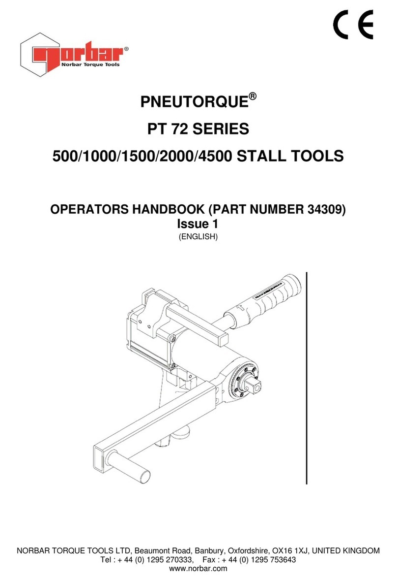
norbar NORTRONIC 34399 User manual

OPERATOR’S MANUAL
NORTRONIC®
Part Number 34399 | Issue 4 | Original Instructions (English)
NORBAR TORQUE TOOLS LTD
Wildmere Road, Banbury,
Oxfordshire, OX16 1JU
UNITED KINGDOM
Tel + 44 (0)1295 270333
Email enquiry@norbar.com
NORBAR TORQUE TOOLS PTY LTD
45–47 Raglan Avenue, Edwardstown,
SA 5039
AUSTRALIA
Tel + 61 (0)8 8292 9777
Email enquiry@norbar.com.au
NORBAR TORQUE TOOLS INC
36400 Biltmore Place, Willoughby,
Ohio, 44094
USA
Tel + 1 866 667 2279
Email inquiry@norbar.us
NORBAR TORQUE TOOLS PTE LTD
194 Pandan Loop
#07-20 Pantech Business Hub
SINGAPORE 128383
Tel + 65 6841 1371
Email enquiries@norbar.sg
NORBAR TORQUE TOOLS (SHANGHAI) LTD
91 Building-7F, No.1122 North Qinzhou Rd,
Xuhui District, Shanghai
CHINA 201103
Tel + 86 21 6145 0368
Email sales@norbar.com.cn
NORBAR TORQUE TOOLS INDIA PVT. LTD
Plot No A-168, Khairne Industrial Area,
Thane Belapur Road, Mahape,
Navi Mumbai – 400 709
INDIA
Tel + 91 22 2778 8480
Email enquiry@norbar.in
www.norbar.com
© Norbar Torque Tools Ltd 2018
www.norbar.com/HowtoUseANorTronic


1
Contents
Introduction 3
Part Numbers Covered by This Manual 3
Parts Included 3
USB Wireless Adapters (accessory) 3
Software Compatibility 3
Features and Functions 4
Before Use 5
Preparation 5
Battery Fitting / Replacement 5
Ratchet Head Fitting / Replacement 5
Button Functions 6
Measure Display 6
Operation 7
Start Up 7
Peak Reading with Manual Reset 7
Peak Reading with Auto Reset 8
Tool Target 8
Targets – Change 9
Zero Display Offset 9
# of Saved Readings 9
Sleep 9
Resume from Sleep (Gyroscope drift calibration) 9
USB Interface 10
Wireless Interface 11
Low Battery 11
Flat Battery 11
Torque CRS 11
Multiplier 11
Exit Measure Display (Options Menu) 12
TDS Receive Results Interface 12
Tool Target - SETTING 13
Set Target 13
Audit mode 13
Set Angle Limit 13
Set Angle Target 13
Set Final Target 14
Linked Targets 14
TDS Target Interface 15
Tool SETUP 16
Torque Limits 17
Angle Limits 18
Units 18
Date & Time 18
Sleep 19
Angle 19
Auto Zero 19
Active From 19
Vibrate 20
Wireless 20
Auto Reset 21
Hold Time 21

2
Display 21
Multiplier 21
Complete 22
Warnings 22
Torque CRS 22
Data Store 23
View Results 23
Erase All 23
About 24
Specifications 25
EU Declaration of Conformity 27
Maintenance 28
NorTronic® Calibration 28
Battery Replacement 28
Repair 28
Cleaning 28
Product Disposal 28
Battery Disposal 28
Trouble Shooting 29
Glossary of Terms 29

3
INTRODUCTION
The NorTronic® is an electronic torque and angle wrench capable of measuring, displaying, storing and
transmitting test results and receiving configuration settings from TDS (Torque Data System PC software) via
the USB or wireless interface.
The tool comes in 3 torque capacities: - 50 N·m, 200 N·m & 330 N·m.
The NorTronic® features 2 identical colour displays positioned at 90 degrees to each other. This enables the
user to see a display when the tool is being operated in the vertical or horizontal plane.
The NorTronic® gives visual, audible and physical indication via vibration that the Tool Target has been reached.
Part Numbers Covered by This Manual
Part Number
Torque
Capacity
Ratchet
Square Drive
Wireless Communication
Frequency
43500
50 N·m
⅜”
868 MHz
43501
50 N·m
½”
868 MHz
43502
200 N·m
½”
868 MHz
43503
330 N·m
½”
868 MHz
43504
50 N·m
⅜”
915 MHz
43505
50 N·m
½”
915 MHz
43506
200 N·m
½”
915 MHz
43507
330 N·m
½”
915 MHz
NorTronic® models 43500, 43501, 43502 & 43503 use an 868MHz wireless frequency; this is designed for
use in Europe.
NorTronic® models 43504, 43505, 43506 & 43507 use a 915MHz wireless frequency; this is designed for use
in USA, Canada, Australia and New Zealand.
For use outside the above areas, disable wireless feature until regulatory approval is obtained.
Parts Included
Parts Included
Part Number
Quantity
NorTronic® electronic torque wrench.
4350X
1
USB flash drive (Manuals / Software).
61131
1
Quick reference guide.
34398
1
USB lead to PC (Mini USB to Type A).
39678
1
AA Rechargeable Battery
39663
3
Calibration Certificate.
-
1
NorTronic® carry case.
44506 - 44508
1
USB Wireless Adapters (Accessory)
USB Wireless Adapters
Part Number
USB Wireless Adapter (868 MHz)
43508
USB Wireless Adapter (915 MHz)
43509
Software Compatibility
NorTronic®
TDS
Reason for upgrade
Version 2.XX
2.0.XX
-
NOTE: ‘X’ is shown in place of the latest software release version #.

4
FEATURES AND FUNCTIONS
• TDS (Torque Data System) software included for complete data management and archiving to a PC.
Includes seamless data synchronisation. See TDS Manual part number 34397 for more information.
• All NorTronic® tools are Torque Handles with a 16mm spigot to interface to additional end fittings and
offsets. A push through ratchet head end fitting is supplied as standard.
• Ability to enter offset compensation for non-standard end fitting.
• NorTronic® can be locked from adjustment “P type” for production environments (via TDS).
• 2 colour 0.95” OLED displays for visual indication of measurement against Target status.
• Audible indication of Target status.
• Vibration feedback when Target reached.
• 4 digit resolution for all NorTronic® electronic torque wrenches.
• Maximum of 2400 (date & time stamped) reading memory store.
• 5 user buttons.
• Operational from three AA internal rechargeable / non rechargeable batteries.
• Up to 15 linked (or non-linked) Targets can be on the tool at any one time.
• USB port for interface to TDS.
• Built in Wireless transceiver for Wireless interface to TDS.
• 12 Torque units.
• Time & date stamped Test Results.
• Displays torque only or torque & angle.
• IP44 protection against dust and water ingress.
• Ability to Ratchet when measuring Angle.
• Directly display and save the output Torque of a HT (Hand Torque) gearbox when used in conjunction
with a NorTronic®.
• Produce, save, view and print Real Time Torque & Angle Graphs in conjunction with TDS.
• View and print Reports for Results in conjunction with TDS.
• 4 Target modes - Torque Target only, Snug Torque followed by Angle Target, Snug Torque followed by
Angle Target + final Torque Target or Audit Torque Target.
• Improved battery life when sleeping (batteries do not need to be removed for storage).
• ASCII mode for interfacing to third party control systems.
5
BEFORE USE
Preparation
IMPORTANT: IF THE EQUIPMENT IS USED IN A MANNER NOT SPECIFIED BY THE MANUFACTURER,
THE PROTECTION PROVIDED BY THE EQUIPMENT MAY BE IMPAIRED.
WARNING: ALLOW THE NORTRONIC® TO EQUALISE TO THE AMBIENT
TEMPERATURE/HUMIDITY BEFORE SWITCHING ON. WIPE OFF ANY
MOISTURE BEFORE USE.
Battery Fitting / Replacement
NOTE: Insert positive battery terminal into handle cavity first. Rotate the end cap clockwise to
tighten and counter-clockwise to release.
Ratchet Head Fitting / Replacement
NOTE: All NorTronic® tools are Torque Handles with a 16mm spigot. Should you wish to change
to a different spanner end fitting, depress the plunger on the ratchet head and pull to
release.
Depress
End cap
Battery +ve

6
11
2
3
4
5
7
9
10
8
1
13
12
6
BUTTON FUNCTIONS
Throughout SETUP and Operation, the buttons perform the following functions:
MEASURE DISPLAY
NOTE: Both of the displays on the NorTronic® show the same information at all times.
#
Function
1
Number of readings that have been saved for the current Target.
2
Shows the next peak reading that will be saved to the NorTronic® (if Auto Reset enabled).
3
Wireless connected to P.C. (TDS).
4
USB connected to P.C. (TDS).
5
Low Battery / Flat Battery.
6
Target less than 10% of Tool Capacity (ISO6789:2017)
7
Current Torque Units.
8
Torque reading.
9
Angle reading.
10
Current Snug Torque & Angle Target.
11
Torque CRS has been changed from default value.
12
Multiplier in use
13
Audit Target
Button
Function
Operation
SETUP
Change Target
Scroll through options or change a
selected value.
When changing a value, hold the button
down for a faster rate of change.
Zero Torque & Angle display if below
the Active From threshold.
Cancel the peak reading if above the
Active From threshold and send via
USB / Wireless.
Confirm a setting.
Exit the measure display.
Exit current menu / screen.
Save test results to NorTronic®.
None
M T = 100 + 30°
29°
332.1
19 I<10% N·m

7
Torque display
Torque input
Reset pressed
Active
From
Zero Torque
OPERATION
Start Up
The NorTronic® does not have a power ON/OFF switch. The NorTronic® is always powered up or in a deep
sleep mode.
Upon fitting the batteries and end cap, press any button to wake the NorTronic® up from sleep. The Norbar
logo is displayed for 2 seconds followed by the measure display:
Peak Reading with Manual Reset Operation
When Torque is applied, the NorTronic® will track the torque input until it has exceeded the Active From
setting (See page 19) and then enters into peak mode for Torque & Angle.
The Angle display is shown as “0°” until the Torque is above the Active From setting for the tool. If the Snug
Torque value is set (See page 13) and is above the Active From setting, the Angle display is shown as “0°”
until the Torque reaches the Snug Torque value and then displays the Angle value in peak mode.
After a Peak Torque or Angle has been applied and then the Torque has dropped below the Active From
setting, both the Torque & Angle readings continuously flash.
Press the ZERO button to Reset the Torque display to the current Torque input and Angle Display
to “0°”.
Press the SAVE button to Reset & Save the peak Torque & Angle readings to the Data Store on
the NorTronic® tool.
If a Target is in use and a reading has been saved, press the UP button (and hold in for 2 seconds)
to delete the last reading that has been saved via the Delete Last Result? confirmation screen.
Delete
Last Result ?
Y / N

8
Hold Time
Active
From
Zero Torque
Torque display
Torque input
Auto Reset
Trigger
Peak Reading with Auto Reset
When Torque is applied, the NorTronic® will track the torque input until it has exceeded the Active From
setting (See page 19) and then enters into peak mode for both Torque & Angle.
The angle display is shown as “0°” until the torque is above the Active From setting for the tool. If the Set
Target (Snug Torque) is set, the angle display is shown as “0°” until the torque reaches the Set Target
(Snug Torque) value (see page 13) and then displays the angle value in peak mode.
When a peak torque or angle has been applied after which the torque has dropped below the Active From
setting, both the torque & angle readings continuously flash for the duration of the Hold Time (see page 21).
The displays are then reset to the current torque input.
If the Save button (which now becomes latching) has been pressed prior to the Peak being
detected, the Torque & Angle readings are saved to the Data Store on the NorTronic®.
If a Target is in use and a reading has been saved, press the UP button (and hold in for 2
seconds) to delete the last reading that has been saved via the Delete Last Result?
confirmation screen.
Delete
Last Result ?
Y / N
Tool Target
Having already set a Tool Target (see page 13 for more details), the NorTronic® beeps as the applied torque
approaches the Torque Target (starting slow and getting faster) until a continuous tone is heard when the
Target has been reached. This stops after the Torque has been released.
The Torque & Angle digits will be shown as:
White = below Active From setting or no Target set
Yellow = above Active From setting, but below Target Lower Limit
Green = above Target Lower Limit and below Target Upper Limit
Red = above Target Upper Limit
The tool Vibrates when the Torque Target or Angle Target has been reached (if enabled in SETUP –
Vibrate, see page 20 for more information).
TIP: If an angle only target has been set, the beeper sounds as the user approaches the angle
target, quickening in frequency until a continuous tone when the angle target has been
reached.

9
Target(s) – Change
Press UP or DOWN to change displayed Target. The UP button has a different function if a
Target is active (see pages 7, 8 & 12).
Zero Display Offset
Exercise the NorTronic® in required direction of use.
Press the ZERO button to Zero both the Torque & Angle values when the Torque is below 3% of the
wrench capacity.
TIP: Zero the NorTronic® in the vertical position with the ratchet head removed, so that the weight
of the tool is not affecting the reading. If the displayed reading does not zero, increase the
reading by applying and maintaining a small torque (<3%) and then press the ZERO button.
Remove the torque and press the button again.
# of Saved Readings
Every time a Test Result is saved to the NorTronic® memory, the Reading # (bottom left of display) is
incremented. This is reset when the Tool Target has been changed.
Sleep
The NorTronic® will Sleep if any of the events listed below have not happened during the time period
specified in Tool SETUP– Sleep (see page 19 for more information):
a) A button has been pressed.
b) The Torque reading has changed by more than 2% of the wrenches capacity.
TIP: The NorTronic® can be forced to sleep at any time by pressing the button for 2 seconds.
Resume from Sleep (Gyroscope drift calibration)
To wake the NorTronic®, press any button. After the display of the Norbar logo the NorTronic® will perform a
gyroscope drift calibration. The Gyroscope drift calculation will also be done if the temperature changes by
more than 3 degrees. This is necessary to ensure the angle measurement is accurate.
5 second countdown to the Gyroscope drift calculation.
WARNING: PLACE THE TOOL ON A FLAT LEVEL SURFACE AND DO NOT MOVE
BEFORE “CALCULATING” IS DISPLAYED.
Do Not Move
Start 5

10
Do Not Move
Calculating
█████
This screen is displayed during the Gyroscope drift calculation.
The NorTronic® can now be used.
NOTE: The Gyro drift calibration will not be done if the NorTronic® is woken less than 30 seconds
after going to sleep.
USB Interface
The NorTronic® can be connected to a PC with TDS installed using the cable supplied.
NOTE: Remove the USB cover to access the USB connector. The USB cover must be fitted for
IP44 protection.
Test Results saved on the NorTronic® (to the Data Store) will be copied to TDS when synchronising. The
Tool Target and Tool SETUP configuration can also be sent from TDS.
When plugged in, the USB icon will appear on the bottom left of the display. When connected to TDS,
the icon will go green.
USB connector

11
Wireless Interface
The NorTronic® can be connected to a PC with TDS installed using an
additional USB Wireless Adapter.
Test Results saved on the NorTronic® (to the Data Store) will be copied to TDS when synchronising. The
Tool Target and Tool SETUP configuration can also be sent to the NorTronic® Tool from TDS.
There are 2 USB Wireless Adapters available:
• 868 MHz (part # 43508) for the UK & Europe
• 915 MHz (part # 43509) for the USA, Canada, Australia & New Zealand.
When connected, the Wireless icon will appear on the bottom left of the display. The Tool can now be
synchronised with TDS.
NOTE: Only NorTronic® tools fitted with the matching Transceiver will work the 868 or 915 MHz
USB Wireless Adapters.
The Wireless Interface must be Enabled in SETUP with the correct 868/915 MHz frequency
(see page 20 for more information).
Multiple Tools must be set up with individual Node numbers (see page 20 for more
information).
Low Battery
The LOW BATTERY icon will be shown when there is approximately 20 minutes of operational life left in the
NorTronic®.
NOTE: This icon will overwrite the Wireless or USB icons (but the NorTronic® will remain
connected).
Flat Battery
The Flat Battery icon will be shown for approximately 30 seconds before shutting down. Further button
presses will not wake up the tool. The batteries must be removed and re-charged or replaced.
NOTE: This icon will overwrite the Wireless or USB icons (but the NorTronic® will remain
connected).
Torque CRS
The Torque CRS (centres) value only needs to be changed if the end fitting has been changed. This setting
ensures the NorTronic® displays the correct Torque when fitting a non-standard spanner end fitting: -
i.e. with a 100mm Torque CRS.
The icon will be shown in the top left hand corner of the Measure display if the Torque CRS value has
been changed from the default value.
Multiplier
The Multiplier value only needs to be changed if a Norbar HT (Hand Torque) Gearbox is being used in
conjunction with the NorTronic®. This setting ensures the NorTronic® displays the correct Torque for the
output of the Torque Multiplier: - i.e. with a 100:1 Ratio.
The M icon will be shown in the top left hand corner of the Measure display if the Multiplier value has
been changed from the default value.
NOTE: This is a Torque only mode, so Angle measurement cannot be displayed.

12
Exit Measure Display (Options Menu)
Press to exit Measure. The Options Menu (shown below) is displayed.
TARGET
SETUP
DATA STORE
ABOUT
Press or to change highlighted option.
Press to confirm.
Press to enter Measure.
TDS Receive Results Interface
Test Results can be sent as they happen (i.e. in real time) from the NorTronic® Tool to TDS via the
Receive Results window using the USB or Wireless interfaces.
Only one tool can be interfaced at any one time.
If the USB interface is used, the USB icon will appear on the bottom left of the display.
If the Wireless interface is used, the Wireless icon will change from to when the tool
is connected to Receive Results in TDS.
After a peak has been detected, press ZERO to send both the peak Torque & Angle values to
Receive Results in TDS. If the tool is configured for Auto Reset, the readings are automatically
sent during the Hold Time.
The save button is inactive (i.e. Test Results are NOT saved on the NorTronic®). When the
button is pressed, Test Results will be sent via USB or wireless to the Receive Results
window on TDS.
If a Target is in use and a reading has been saved, press the UP button (and hold in for 2
seconds) to delete the last reading that has been output to "Receive Results" in TDS.

13
TOOL TARGET - SETTING
Set Target
Set Target
N·m
0.0
Press or to change.
Press to confirm and go to the Audit mode?.
The button is not functional.
• Minimum = 0 (No Target), Maximum = 100% of NorTronic® Torque capacity.
Audit mode
NOTE: This screen will only be shown if Angle is Enabled ‘✓’ in SETUP and Target is larger than
‘Active from’ threshold.
Audit mode?
✘
Press or to enable ‘✓’ or disable ‘✘’.
Press to confirm and go to either Set Angle Limit
or Set Angle.
The button is not functional.
• ‘✓’ go to Set Angle Limit, ‘✘’ go to Set Angle.
Set Angle Limit
NOTE: This screen will only be shown if ‘✓’ was selected on the Audit mode? screen.
Set Angle Limit
5°
Press or to change value.
Press to confirm and go to Options Menu.
The button is not functional.
• Minimum = 1, Maximum = 720.
Set Angle Target
NOTE: This screen will only be shown if ‘’ was selected on the Audit mode? screen.
Set Angle
32°
Press or to change.
Press to confirm and go to Set Torque Target.
The button is not functional.
• Minimum = 0, Maximum = 999.

14
Set Final Torque Target
NOTE: This screen will only be shown if Angle Target is larger than ‘0’ on the ‘Set Angle’ screen.
Set Final
N·m
298.4
Press or to change.
Press to confirm and go to Options Menu.
The button is not functional.
• Minimum = 0 (No Final Torque Target),, Maximum = NorTronic® Torque capacity.
• If the Final Target value is set to 0, the Final Target is disabled (Torque + Angle Target), if it is set to a
value above the Torque Target setting, the Final Target is enabled (Torque + Angle (with Final
Torque) Target.
Linked Targets
Linked Targets can only be set up in TDS.
The # of Tests & Next Target can
only be specified in the TDS
Target.
Linked Targets can be sent via the
USB or Wireless interface to the
Tool.
If after the final Target has
completed (and No further Target
has been specified), the last Target
is enabled.
To carry on, link the last Target to
the first.

15
TDS Target interface
The NorTronic® has up to 15 active Targets. Multiple Targets can be set up in TDS and individually
downloaded to NorTronic®.
The Target can be changed on the tool unless the “Locked” option has been ticked in “Set Tool Options”
and downloaded to the NorTronic® by clicking the Update button on “Set Tool Options” as shown below
(See page 16 for more information on “Tool Setup”).
The Locked option disables the NorTronic® user from altering the Target SETTING and Tool SETUP on the
NorTronic®.

16
TOOL - SETUP
All NorTronic® Tool - SETUP can be configured in TDS
and downloaded to the tool.
NorTronic® Tool - SETUP
includes: Limits, Units, Time &
Date, Sleep, Angle Display,
Auto Zero, Active From,
Vibrate, Wireless, Auto Reset,
Inverse Display, Torque
Centres and Multiplier.
NOTE: Tool - SETUP is
active unless the
“Lock” option has
been ticked and
downloaded to
NorTronic® via the
TDS software. This
disables the
NorTronic® user from
altering the Tool
SETUP or Target
SETTING.

17
LIMITS
UNITS
DATE / TIME
SLEEP
Press or to highlight required setting.
Press to confirm the setting to change.
Press to exit to the Options Menu.
ANGLE
AUTO ZERO
ACTIVE FROM
VIBRATE
WIRELESS
AUTO RESET
DISPLAY
MULTIPLIER
COMPLETE
WARNINGS
TORQUE CRS
Torque Limits
Torque ?
HI Limit 4
LO Limit 4
Press or to change highlighted value.
Press to confirm and go to LO Limit.
Press to exit to SETUP (saving changes).
• % of Torque Target setting: Minimum = 0, Maximum = 20. Default = 4.
NOTE: Tool - SETUP is a scrolling screen. Press
the DOWN button with SLEEP highlighted
to go to ANGLE etc.

18
Angle Limits
Angle ?
HI Limit 4
LO Limit 4
Press or to change highlighted value.
Press to confirm and go to LO Limit.
Press to exit to SETUP (saving changes).
• Target + HI Limit, Target - LO Limit in degrees (°).
• Minimum = 0, Maximum = 20. Default = 4.
Units
Units ?
N·m Kgf·m
dN·m Kgf·cm
cN·m gf·m
Press or to highlight required unit.
Press to select Unit and Exit.
Press to exit to SETUP (no changes).
• Press the button with ‘gf·m’ highlighted to go to 2nd units screen (shown below).
Units ?
lbf·ft in·lb
lbf·in ozf·in
ft·lb in·oz
Press or to highlight unit.
Press to select Unit and Exit.
Press to exit to SETUP (no changes).
• Minimum Enabled = 1, Maximum Enabled = 1. Default = N.m.
Date & Time
Date & Time ?
24 01 14
16:05:14
Press or to change highlighted value.
Press or to confirm and step onto next change
(month, year, hours, minutes & seconds).
• 24 hour clock format. The Time & Date will always be checked and updated when synchronising to TDS.
• Date format can be changed in TDS Set Tool Options, DD/MM/YY, MM/DD/YY or YY/MM/DD.
Table of contents
Other norbar Tools manuals

norbar
norbar PNEUTORQUE PT 72/1000 Service manual

norbar
norbar PNEUTORQUE PTM series User manual

norbar
norbar Secondary Handle User manual

norbar
norbar PTM-IC Series User manual

norbar
norbar PneuTorque Standard Series User manual

norbar
norbar PNEUTORQUE PTM User manual

norbar
norbar TT20 N.m User manual

norbar
norbar 13295 User manual

norbar
norbar PneuTorque Standard Series User manual

norbar
norbar ISO 1500 Service manual