Makita HR2650 User manual

HR2650
HR2651
HR2651T
HR2661
EN Combination Hammer with
Self Dust Collection INSTRUCTION MANUAL 7
SV Kombinationshammare med
dammuppsamling BRUKSANVISNING 14
NO Kombihammer med
støvsamler BRUKSANVISNING 21
FI Iskuporakoneyhdistelmä
omalla pölynkerääjällä KÄYTTÖOHJE 28
LV Kombinētais veseris ar
putekļu savācēju LIETOŠANAS INSTRUKCIJA 35
LT
Kombinacinis plaktukas su
savaiminio dulkių surinkimo
funkcija
NAUDOJIMO INSTRUKCIJA 42
ET Tolmukogujaga
kombineeritud haamer KASUTUSJUHEND 49
RU Перфоратор С Системой
Пылеудаления
РУКОВОДСТВО ПО
ЭКСПЛУАТАЦИИ 56

2
1
Fig.1
2
1
Fig.2
1
B
A
Fig.3
11
A
B
Fig.4
21
3
Fig.5
21
34
Fig.6
1 2
Fig.7
1
Fig.8
2

1
Fig.9
12
Fig.10
1A
Fig.11
1
Fig.12
1
Fig.13
1
2
Fig.14
1
Fig.15
1
2
Fig.16
3

1
Fig.17
1
2
Fig.18
1
Fig.19
1
Fig.20
1
2
Fig.21
1
Fig.22
1
2
Fig.23
Fig.24
4

Fig.25
Fig.26
Fig.27
1 2
Fig.28
1
2
Fig.29
1
Fig.30
1
Fig.31
Fig.32
5

Fig.33
Fig.34
1
Fig.35
1
2
Fig.36
1
2
Fig.37
1
2
Fig.38
1
2
Fig.39
6

7ENGLISH
ENGLISH (Original instructions)
SPECIFICATIONS
Model: HR2650 HR2651 HR2651T HR2661
Capacities Concrete 26 mm
Core bit 68 mm
Diamond core bit (dry type) 80 mm
Steel 13 mm
Wood 32 mm
No load speed 0 - 1,200 min-1 0 - 1,100 min-1
Blows per minute 0 - 4,600 min-1 0 - 4,500 min-1
Overall length 604 mm 630 mm 666 mm
Net weight 3.0 - 4.1 kg 3.1 - 4.2 kg 3.2 - 4.4 kg 3.3 - 4.4 kg
Safety class /II
• Duetoourcontinuingprogramofresearchanddevelopment,thespecicationshereinaresubjecttochange
without notice.
• Specicationsmaydifferfromcountrytocountry.
• Theweightmaydifferdependingontheattachment(s).Thelightestandheaviestcombination,accordingto
EPTA-Procedure01/2014,areshowninthetable.
Intended use
Thetoolisintendedforhammerdrillinganddrillingin
brick, concrete and stone.
It is also suitable for drilling without impact in wood,
metal, ceramic and plastic.
Power supply
Thetoolshouldbeconnectedonlytoapowersupplyof
the same voltage as indicated on the nameplate, and
canonlybeoperatedonsingle-phaseACsupply.They
are double-insulated and can, therefore, also be used
from sockets without earth wire.
Noise
ThetypicalA-weightednoiseleveldeterminedaccord-
ing to EN60745:
Model HR2650
Sound pressure level (LpA):91dB(A)
Sound power level (LWA):102dB(A)
Uncertainty(K):3dB(A)
Model HR2651
Sound pressure level (LpA):92dB(A)
Sound power level (LWA):103dB(A)
Uncertainty(K):3dB(A)
Model HR2651T
Sound pressure level (LpA):92dB(A)
Sound power level (LWA):103dB(A)
Uncertainty(K):3dB(A)
Model HR2661
Sound pressure level (LpA):90dB(A)
Sound power level (LWA):101dB(A)
Uncertainty(K):3dB(A)
WARNING: Wear ear protection.
Vibration
Thevibrationtotalvalue(tri-axialvectorsum)deter-
mined according to EN60745:
Model HR2650
Work mode: hammer drilling into concrete
Vibration emission (ah, HD): 12.5 m/s2
Uncertainty (K) : 1.5 m/s2
Work mode: chiselling function with side grip
Vibration emission (ah, Cheq): 9.5 m/s2
Uncertainty (K) : 1.5 m/s2
Work mode: drilling into metal
Vibration emission (ah,D) : 2.5 m/s2
Uncertainty (K) : 1.5 m/s2
Model HR2651
Work mode: hammer drilling into concrete
Vibration emission (ah, HD): 11.5 m/s2
Uncertainty (K) : 1.5 m/s2
Work mode: chiselling function with side grip
Vibration emission (ah, Cheq): 9.0 m/s2
Uncertainty (K) : 1.5 m/s2
Work mode: drilling into metal
Vibration emission (ah,D) : 2.5 m/s2
Uncertainty (K) : 1.5 m/s2
Model HR2651T
Work mode: hammer drilling into concrete
Vibration emission (ah, HD): 11.5 m/s2
Uncertainty (K) : 1.5 m/s2
Work mode: chiselling function with side grip
Vibration emission (ah, Cheq): 9.0 m/s2
Uncertainty (K) : 1.5 m/s2
Work mode: drilling into metal
Vibration emission (ah,D) : 2.5 m/s2
Uncertainty (K) : 1.5 m/s2
Model HR2661
Work mode: hammer drilling into concrete
Vibration emission (ah, HD): 9.5 m/s2
Uncertainty (K) : 1.5 m/s2

8ENGLISH
Work mode: chiselling function with side grip
Vibration emission (ah, Cheq): 6.0 m/s2
Uncertainty (K) : 1.5 m/s2
Work mode: drilling into metal
Vibration emission (ah,D) : 2.5 m/s2or less
Uncertainty (K) : 1.5 m/s2
NOTE:Thedeclaredvibrationemissionvaluehas
been measured in accordance with the standard test
method and may be used for comparing one tool with
another.
NOTE:
Thedeclaredvibrationemissionvaluemay
alsobeusedinapreliminaryassessmentofexposure.
WARNING:Thevibrationemissionduringactual
use of the power tool can differ from the declared
emission value depending on the ways in which the
tool is used.
WARNING: Be sure to identify safety measures
to protect the operator that are based on an estima-
tionofexposureintheactualconditionsofuse(taking
account of all parts of the operating cycle such as
the times when the tool is switched off and when it is
running idle in addition to the trigger time).
EC Declaration of Conformity
For European countries only
TheECdeclarationofconformityisincludedasAnnexA
to this instruction manual.
SAFETY WARNINGS
General power tool safety warnings
WARNING: Read all safety warnings, instruc-
tions, illustrations and specications provided
with this power tool. Failure to follow all instructions
listedbelowmayresultinelectricshock,reand/or
seriousinjury.
Save all warnings and instruc-
tions for future reference.
Theterm"powertool"inthewarningsreferstoyour
mains-operated (corded) power tool or battery-operated
(cordless) power tool.
ROTARY HAMMER SAFETY
WARNINGS
1. Wear ear protectors.Exposuretonoisecan
cause hearing loss.
2. Use auxiliary handle(s), if supplied with the
tool.Lossofcontrolcancausepersonalinjury.
3. Hold power tool by insulated gripping sur-
faces, when performing an operation where
the cutting accessory may contact hidden wir-
ing or its own cord. Cutting accessory contacting
a"live"wiremaymakeexposedmetalpartsofthe
powertool"live"andcouldgivetheoperatoran
electric shock.
4. Wear a hard hat (safety helmet), safety glasses
and/or face shield. Ordinary eye or sun glasses
are NOT safety glasses. It is also highly recom-
mended that you wear a dust mask and thickly
padded gloves.
5. Be sure the bit is secured in place before
operation.
6. Under normal operation, the tool is designed
to produce vibration. The screws can come
loose easily, causing a breakdown or accident.
Check tightness of screws carefully before
operation.
7. In cold weather or when the tool has not been
used for a long time, let the tool warm up for
a while by operating it under no load. This
will loosen up the lubrication. Without proper
warm-up, hammering operation is difcult.
8. Always be sure you have a rm footing. Be
sure no one is below when using the tool in
high locations.
9. Hold the tool rmly with both hands.
10. Keep hands away from moving parts.
11. Do not leave the tool running. Operate the tool
only when hand-held.
12. Do not point the tool at any one in the area
when operating. The bit could y out and
injure someone seriously.
13. Do not touch the bit, parts close to the bit, or
workpiece immediately after operation; they
may be extremely hot and could burn your
skin.
14. Some material contains chemicals which may
be toxic. Take caution to prevent dust inhala-
tion and skin contact. Follow material supplier
safety data.
15. Do not touch the power plug with wet hands.
SAVE THESE INSTRUCTIONS.
WARNING: DO NOT let comfort or familiarity
with product (gained from repeated use) replace
strict adherence to safety rules for the subject
product. MISUSE or failure to follow the safety
rules stated in this instruction manual may cause
serious personal injury.

9ENGLISH
FUNCTIONAL
DESCRIPTION
CAUTION: Always be sure that the tool is
switched off and unplugged before adjusting or
checking function on the tool.
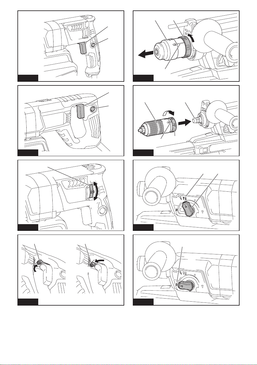
Switch action
CAUTION: Before plugging in the tool, always
check to see that the switch trigger actuates
properly and returns to the "OFF" position when
released.
CAUTION: Switch can be locked in “ON” posi-
tion for ease of operator comfort during extended
use. Apply caution when locking tool in “ON”
position and maintain rm grasp on tool.
►Fig.1: 1. Switch trigger 2. Lock button
►Fig.2: 1. Switch trigger 2. Lock button
Tostartthetool,simplypulltheswitchtrigger.Tool
speed is increased by increasing pressure on the switch
trigger. Release the switch trigger to stop.
For continuous operation, pull the switch trigger, push
in the lock button and then release the switch trigger.
Tostopthetoolfromthelockedposition,pulltheswitch
trigger fully, then release it.
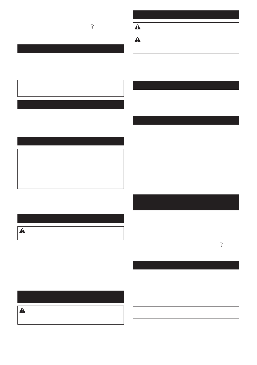
Reversing switch action
CAUTION: Always check the direction of
rotation before operation.
NOTICE:
Use the reversing switch only after the
tool comes to a complete stop. Changing the direction
of rotation before the tool stops may damage the tool.
NOTICE:
If the switch trigger cannot be depressed,
check to see that the reversing switch is fully set to
position / (A side) or / (B side).
For HR2650/HR2651/HR2651T
Thistoolhasareversingswitchtochangethedirec-
tion of rotation. Move the reversing switch lever to the
position (Aside)forclockwiserotationortotheposi-
tion (B side) for counterclockwise rotation.
►Fig.3: 1. Reversing switch lever
For HR2661
Thistoolhasareversingswitchtochangethedirec-
tion of rotation. Move the reversing switch lever to
the position(Aside)forclockwiserotationor
the position (B side) for counterclockwise rotation.
►Fig.4: 1. Reversing switch lever
NOTE: When you operate the tool in counterclock-
wise rotation, the switch trigger is pulled only halfway
and the tool runs at half speed. For counterclockwise
rotation, you cannot push in the lock button.
Changing the quick change chuck
for SDS-plus
For HR2651T
ThequickchangechuckforSDS-pluscanbeeasily
exchangedforthequickchangedrillchuck.
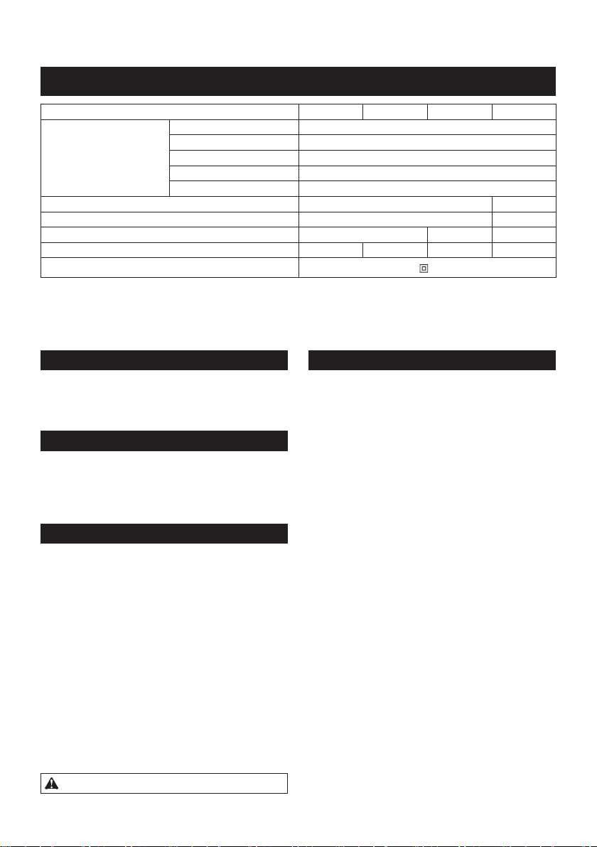
Removing the quick change chuck
for SDS-plus
CAUTION: Before removing the quick change
chuck for SDS-plus, be sure to remove the bit.
Grasp the change cover of the quick change chuck
for SDS-plus and turn in the direction of the arrow
until the change cover line moves from the symbol
to the symbol. Pull forcefully in the direction of the
arrow.
►Fig.5: 1. Quick change chuck for SDS-plus
2. Change cover 3. Change cover line
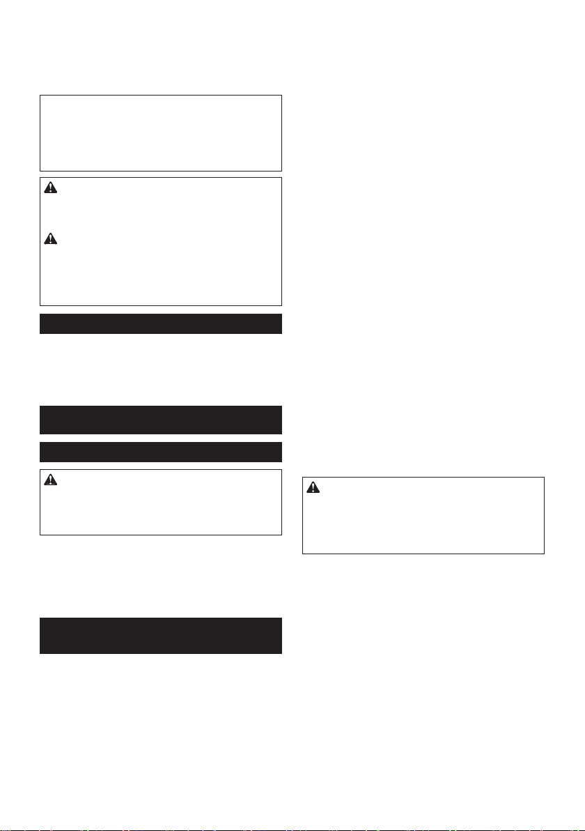
Installing the quick change drill
chuck
Check the line of the quick change drill chuck shows
the symbol. Grasp the change cover of the quick
change drill chuck and set the line to the symbol.
Place the quick change drill chuck on the spindle of the
tool. Grasp the change cover of the quick change drill
chuck and turn the change cover line to the symbol
until a click can clearly be heard.
►Fig.6: 1. Quick change drill chuck 2. Spindle
3. Change cover line 4. Change cover
Selecting the action mode
NOTICE: Do not rotate the action mode chang-
ing knob when the tool is running.Thetoolwillbe
damaged.
NOTICE: To avoid rapid wear on the mode
change mechanism, be sure that the action mode
changing knob is always positively located in one
of the three action mode positions.
Rotation with hammering
For drilling in concrete, masonry, etc., rotate the action
mode changing knob to the symbol. Use a tungsten-
carbide tipped bit (optional accessory).
►Fig.7: 1. Rotation with hammering 2.Actionmode
changing knob
Rotation only
For drilling in wood, metal or plastic materials, rotate
the action mode changing knob to the symbol. Use a
twist drill bit or wood drill bit.
►Fig.8: 1. Rotation only

10 ENGLISH
Hammering only
For chipping, scaling or demolition operations, rotate
the action mode changing knob to the symbol. Use a
bull point, cold chisel, scaling chisel, etc.
►Fig.9: 1. Hammering only
Adjusting the nozzle position
Pushintheguidewhilepressingtheguideadjustment
button, and then release the button at the desired
position.
►Fig.10: 1. Guide 2.Guideadjustmentbutton
NOTE:Beforeadjustingthenozzleposition,release
thenozzleforwardcompletelybypressingtheguide
adjustmentbutton.
Adjusting the drilling depth
Slidethedepthadjustmentbuttontothedesiredposi-
tionwhilepressingit.Thedistance(A)isthedrilling
depth.
►Fig.11: 1.Depthadjustmentbutton
Torque limiter
NOTICE: As soon as the torque limiter actuates,
switch off the tool immediately.Thiswillhelppre-
vent premature wear of the tool.
NOTICE: Drill bits such as hole saw, which tend
to pinch or catch easily in the hole, are not appro-
priate for this tool.Thisisbecausetheywillcause
the torque limiter to actuate too frequently.
Thetorquelimiterwillactuatewhenacertaintorque
levelisreached.Themotorwilldisengagefromthe
output shaft. When this happens, the drill bit will stop
turning.
Hook
CAUTION: Never hook the tool at high loca-
tion or on potentially unstable surface.
For HR2661
►Fig.12: 1. Hook
Thehookisconvenientfortemporarilyhangingthetool.
Tousethehook,simplyliftuphookuntilitsnapsinto
the open position. When not in use, always lower hook
until it snaps into the closed position.
ASSEMBLY
CAUTION: Always be sure that the tool is
switched off and unplugged before carrying out
any work on the tool.
Side grip (auxiliary handle)
CAUTION: Always use the side grip to ensure
safe operation.
CAUTION: After installing or adjusting the
side grip, make sure that the side grip is rmly
secured.
Installthesidegripsothatthegroovesonthegriptin
theprotrusionsonthetoolbarrel.Turnthegripclock-
wisetosecureit.Thegripcanbexedatdesiredangle.
►Fig.13: 1. Side grip
Grease
Coat the shank end of the drill bit beforehand with a
small amount of grease (about 0.5 - 1 g).
Thischucklubricationassuressmoothactionandlon-
ger service life.
Installing or removing drill bit
Clean the shank end of the drill bit and apply grease
before installing the drill bit.
►Fig.14: 1. Shank end 2. Grease
Insertthedrillbitintothetool.Turnthedrillbitandpush
it in until it engages.
Afterinstallingthedrillbit,alwaysmakesurethatthe
drill bit is securely held in place by trying to pull it out.
►Fig.15: 1. Drill bit
Toremovethedrillbit,pullthechuckcoverdownallthe
way and pull the drill bit out.
►Fig.16: 1. Drill bit 2. Chuck cover
Chisel angle (when chipping,
scaling or demolishing)
Thechiselcanbesecuredatthedesiredangle.To
change the chisel angle, rotate the action mode chang-
ingknobtotheOsymbol.Turnthechiseltothedesired
angle.
►Fig.17: 1.Actionmodechangingknob
Rotate the action mode changing knob to the sym-
bol.Thenmakesurethatthechiselissecurelyheldin
place by turning it slightly.
Depth gauge
Thedepthgaugeisconvenientfordrillingholesof
uniform depth. Loosen the side grip and insert the depth
gaugeintotheholeonthesidegrip.Adjustthedepth
gauge to the desired depth and tighten the side grip
rmly.
►Fig.18: 1. Hole 2. Depth gauge
NOTE: Make sure that the depth gauge does not
touch the main body of the tool when attaching it.

11 ENGLISH
Installing or removing dust
collection system
Toremovethedustcollectionsystem,pullthetoolwhile
pressingthelock-offbutton.Toinstallit,insertthetool
into the dust collection system all the way until it locks in
place with a little click.
►Fig.19: 1. Lock-off button
Dust cup
Optional accessory
Use the dust cup to prevent dust from falling over the
tool and on yourself when performing overhead drilling
operations.Attachthedustcuptothebitasshownin
thegure.Thesizeofbitswhichthedustcupcanbe
attached to is as follows.
Model Bit diameter
Dust cup 5 6 mm - 14.5 mm
Dust cup 9 12 mm - 16 mm
►Fig.20: 1. Dust cup
Dust cup set
Optional accessory
Before installing the dust cup set, remove the bit from
the tool if installed.
Install the dust cup set on the tool so that the sym-
bol on the dust cup is aligned with the groove in the tool.
►Fig.21: 1. symbol 2. Groove
NOTE: If you connect a vacuum cleaner to the dust
cup set, remove the dust cap before connecting it.
►Fig.22: 1. Dust cap
Toremovethedustcupset,removethebitwhilepulling
the chuck cover in the direction of the arrow.
►Fig.23: 1. Bit 2. Chuck cover
Hold the root of dust cup and pull it out.
►Fig.24
NOTE: If the cap comes off from the dust cup, attach
it with its printed side facing up so that groove on the
captsintheinsideperipheryoftheattachment.
►Fig.25
OPERATION
CAUTION: Always use the side grip (auxiliary
handle) and rmly hold the tool by both side grip
and switch handle during operations.
CAUTION: Always make sure that the work-
piece is secured before operation.
CAUTION: The dust collection system is
intended for drilling in concrete only. Do not use
the dust collection system for drilling in metal or
wood.
CAUTION: When using the tool with the dust
collection system, be sure to attach the lter
to the dust collection system to prevent dust
inhalation.
CAUTION: Before using the dust collection
system, check that the lter is not damaged.
Failure to do so may cause dust inhalation.
CAUTION: The dust collection system col-
lects the generated dust at a considerable rate,
but not all dust can be collected.
NOTICE: Do not use the dust collection system
for core drilling or chiseling.
NOTICE: Do not use the dust collection system
for drilling in wet concrete or use this system
in wet environment. Failure to do so may cause
malfunction.
►Fig.26
Hammer drilling operation
CAUTION:Thereistremendousandsudden
twistingforceexertedonthetool/drillbitatthetimeof
hole break-through, when the hole becomes clogged
with chips and particles, or when striking reinforcing
rods embedded in the concrete. Always use the side
grip (auxiliary handle) and rmly hold the tool by
both side grip and switch handle during opera-
tions. Failure to do so may result in the loss of control
ofthetoolandpotentiallysevereinjury.
Set the action mode changing knob to the symbol.
Position the drill bit at the desired location for the hole,
then pull the switch trigger. Do not force the tool. Light
pressure gives best results. Keep the tool in position
and prevent it from slipping away from the hole.
Do not apply more pressure when the hole becomes
clogged with chips or particles. Instead, run the tool at
an idle, then remove the drill bit partially from the hole.
By repeating this several times, the hole will be cleaned
out and normal drilling may be resumed.
NOTE: Eccentricity in the drill bit rotation may occur
whileoperatingthetoolwithnoload.Thetoolauto-
maticallycentersitselfduringoperation.Thisdoesnot
affect the drilling precision.
Chipping/Scaling/Demolition
Set the action mode changing knob to the symbol.
Holdthetoolrmlywithbothhands.Turnthetoolon
and apply slight pressure on the tool so that the tool will
not bounce around, uncontrolled.
Pressing very hard on the tool will not increase the
efciency.
►Fig.27

12 ENGLISH
Drilling in wood or metal
CAUTION: Hold the tool rmly and exert care
when the drill bit begins to break through the
workpiece.Thereisatremendousforceexertedon
the tool/drill bit at the time of hole break through.
CAUTION: A stuck drill bit can be removed
simply by setting the reversing switch to reverse
rotation in order to back out. However, the tool
may back out abruptly if you do not hold it rmly.
CAUTION: Always secure workpieces in a
vise or similar hold-down device.
NOTICE: Never use “rotation with hammering”
when the drill chuck is installed on the tool.The
drill chuck may be damaged.
Also,thedrillchuckwillcomeoffwhenreversingthe
tool.
NOTICE: Pressing excessively on the tool will
not speed up the drilling.Infact,thisexcessive
pressure will only serve to damage the tip of your drill
bit, decrease the tool performance and shorten the
service life of the tool.
Set the action mode changing knob to the symbol.
For HR2650/HR2651/HR2661
Optional accessory
Attachthechuckadaptertoakeylessdrillchuckto
which1/2"-20sizescrewcanbeinstalled,andthen
install them to the tool. When installing it, refer to the
section “Installing or removing drill bit”.
►Fig.28: 1. Keyless drill chuck 2. Chuck adapter
For HR2651T
Use the quick change drill chuck as standard equip-
ment.Wheninstallingit,referto"changingthequick
changechuckforSDS-plus".
Hold the ring and turn the sleeve counterclockwise to
openthechuckjaws.Placethebitinthechuckasfaras
itwillgo.Holdtheringrmlyandturnthesleeveclock-
wise to tighten the chuck.
►Fig.29: 1. Sleeve 2. Ring
Toremovethebit,holdtheringandturnthesleeve
counterclockwise.
Diamond core drilling
NOTICE: If performing diamond core drilling
operations using “rotation with hammering”
action, the diamond core bit may be damaged.
When performing diamond core drilling operations,
always set the change lever to the position to use
"rotationonly"action.
Disposing of dust
CAUTION: Always be sure that the tool is
switched off and unplugged before carrying out
any work on the tool.
CAUTION: Be sure to wear dust mask when
disposing of dust.
CAUTION: Empty the dust case regularly
before the dust case becomes full. Failure to do so
may decrease the dust collection performance and
cause dust inhalation.
CAUTION: The performance of dust collection
decreases if the lter in the dust case become
clogged. Replace the lter with new one after
approximately 200 times of dust fulllment as a
guide. Failure to do so may cause dust inhalation.
1. Remove the dust case while pressing down the
lever of the dust case.
►Fig.30: 1. Lever
2. Open the cover of the dust case.
►Fig.31: 1. Cover
3. Disposeofthedust,andthencleanthelter.
►Fig.32
NOTICE: When cleaning the lter, do not touch
the lter with brush or similar, or blow com-
pressed air on the lter. It may damage the lter.
Blow-out bulb
Optional accessory
Afterdrillingthehole,usetheblow-outbulbtocleanthe
dust out of the hole.
►Fig.33
Using dust cup set
Optional accessory
Fit the dust cup set against the ceiling when operating
the tool.
►Fig.34
NOTICE:
Do not use the dust cup set when drilling
in metal or similar. It may damage the dust cup set due
to the heat produced by small metal dust or similar.
NOTICE: Do not install or remove the dust cup
set with the drill bit installed in the tool. It may
damage the dust cup set and cause dust leak.
MAINTENANCE
CAUTION: Always be sure that the tool is
switched off and unplugged before attempting to
perform inspection or maintenance.
NOTICE: Never use gasoline, benzine, thinner,
alcohol or the like. Discoloration, deformation or
cracks may result.
TomaintainproductSAFETYandRELIABILITY,
repairs,anyothermaintenanceoradjustmentshould
beperformedbyMakitaAuthorizedorFactoryService
Centers, always using Makita replacement parts.

13 ENGLISH
Replacing lter of dust case
1. Remove the dust case while pressing down the
lever of the dust case.
►Fig.35: 1. Lever
2. Inserttheat-bladescrewdriverintotheslotsof
theltercovertoremovetheltercaseandlter.
►Fig.36: 1. Flat-blade screwdriver 2. Filter case
3. Removethelterfromtheltercase.
►Fig.37: 1. Filter 2. Filter case
4. Attachanewltertotheltercase,andthen
attach them to the dust case aligning the protrusion on
theltercasewiththegrooveonthedustcase.
►Fig.38: 1. Protrusion 2. Groove
5. Close the cover of the dust case, and then attach
it to the tool.
Replacing sealing cap
If the sealing cap is worn out, the performance of the
dust collection decreases. Replace it if it's worn out.
Remove the sealing cap, and then attach a new one
with its protrusion facing upward.
►Fig.39: 1. Protrusion 2. Sealing cap
OPTIONAL
ACCESSORIES
CAUTION:
These accessories or attachments
are recommended for use with your Makita tool spec-
ied in this manual.Theuseofanyotheraccessoriesor
attachmentsmightpresentariskofinjurytopersons.Only
use accessory or attachment for its stated purpose.
If you need any assistance for more details regarding
these accessories, ask your local Makita Service Center.
• Carbide-tippeddrillbits(SDS-Pluscarbide-tipped
bits)
• Corebit
• Bullpoint
• Diamondcorebit
• Coldchisel
• Scalingchisel
• Groovingchisel
• Chuckadapter
• Keylessdrillchuck
• Bitgrease
• Depthgauge
• Blow-outbulb
• Dustcup
• Dustcupset
• Safetygoggles
• Plasticcarryingcase
NOTE: Some items in the list may be included in the
toolpackageasstandardaccessories.Theymay
differ from country to country.

14 SVENSKA
SVENSKA (Originalinstruktioner)
SPECIFIKATIONER
Modell: HR2650 HR2651 HR2651T HR2661
Kapaciteter Cement 26 mm
Borrkrona 68 mm
Borr med diamantkrona (torr
modell)
80 mm
Stål 13 mm
Trä 32 mm
Hastighet utan belastning 0 - 1 200 min-1 0 - 1 100 min-1
Slag per minut 0 - 4 600 min-1 0 - 4 500 min-1
Totallängd 604 mm 630 mm 666 mm
Nettovikt 3,0 - 4,1 kg 3,1 - 4,2 kg 3,2 - 4,4 kg 3,3 - 4,4 kg
Säkerhetsklass /II
• Pågrundavvårtpågåendeprogramförforskningochutvecklingkandessaspecikationerändrasutanföregå-
ende meddelande.
• Specikationerkanvarieramellanolikaländer.
• Viktenkanvarieraberoendepåtillbehören.DenlättasteochdentyngstakombinationenenligtEPTA-procedur
01/2014 visas i tabellen.
Avsedd användning
Maskinenäravseddförslagborrningochborrningi
tegel, betong och sten.
Denärävenlämpadförborrningutanslagiträ,metall,
keramik och plast.
Strömförsörjning
Maskinenfårendastanslutastillelnätmedsamma
spänningsomangespåtypplåtenochmedenfasig
växelström.Deärdubbelisoleradeochfårdärförockså
anslutasiojordadevägguttag.
Buller
DennormalabullernivånförA-belastningärbestämd
enligt EN60745:
Model HR2650
Ljudtrycksnivå(LpA):91dB(A)
Ljudeffektnivå(LWA):102dB(A)
Mättolerans(K):3dB(A)
Model HR2651
Ljudtrycksnivå(LpA):92dB(A)
Ljudeffektnivå(LWA):103dB(A)
Mättolerans(K):3dB(A)
Model HR2651T
Ljudtrycksnivå(LpA):92dB(A)
Ljudeffektnivå(LWA):103dB(A)
Mättolerans(K):3dB(A)
Model HR2661
Ljudtrycksnivå(LpA):90dB(A)
Ljudeffektnivå(LWA):101dB(A)
Mättolerans(K):3dB(A)
VARNING: Använd hörselskydd.
Vibration
Dettotalavibrationsvärdet(treaxladvektorsumma)
bestämtenligtEN60745:
Model HR2650
Arbetsläge:slagborrningibetong
Vibrationsemission (ah, HD): 12,5 m/s2
Mättolerans(K):1,5m/s2
Arbetsläge:bearbetningsfunktionmedsidohandtag
Vibrationsemission (ah, Cheq): 9,5 m/s2
Mättolerans(K):1,5m/s2
Arbetsläge:borrningimetall
Vibrationsemission (ah,D) : 2,5 m/s2
Mättolerans(K):1,5m/s2
Model HR2651
Arbetsläge:slagborrningibetong
Vibrationsemission (ah, HD): 11,5 m/s2
Mättolerans(K):1,5m/s2
Arbetsläge:bearbetningsfunktionmedsidohandtag
Vibrationsemission (ah, Cheq): 9,0 m/s2
Mättolerans(K):1,5m/s2
Arbetsläge:borrningimetall
Vibrationsemission (ah,D) : 2,5 m/s2
Mättolerans(K):1,5m/s2
Model HR2651T
Arbetsläge:slagborrningibetong
Vibrationsemission (ah, HD): 11,5 m/s2
Mättolerans(K):1,5m/s2
Arbetsläge:bearbetningsfunktionmedsidohandtag
Vibrationsemission (ah, Cheq): 9,0 m/s2
Mättolerans(K):1,5m/s2
Arbetsläge:borrningimetall
Vibrationsemission (ah,D) : 2,5 m/s2
Mättolerans(K):1,5m/s2

15 SVENSKA
Model HR2661
Arbetsläge:slagborrningibetong
Vibrationsemission (ah, HD): 9,5 m/s2
Mättolerans(K):1,5m/s2
Arbetsläge:bearbetningsfunktionmedsidohandtag
Vibrationsemission (ah, Cheq): 6,0 m/s2
Mättolerans(K):1,5m/s2
Arbetsläge:borrningimetall
Vibrationsemission (ah,D) : 2,5 m/s2ellerlägre
Mättolerans(K):1,5m/s2
OBS:Detdeklareradevibrationsemissionsvärdet
haruppmättsienlighetmedstandardtestmetoden
ochkananvändasförattjämföraenmaskinmeden
annan.
OBS:Detdeklareradevibrationsemissionsvärdetkan
ocksåanvändasienpreliminärbedömningavexpo-
neringförvibration.
VARNING: Viberationsemissionen under faktisk
användningavmaskinenkanskiljasigfråndetdekla-
reradeemissionsvärdet,beroendepåhurmaskinen
används.
VARNING:Varnogamedattidentierasäker-
hetsåtgärderförattskyddaanvändaren,vilkaärgrun-
dadepåenuppskattningavgradenavexponering
förvibrationerunderdefaktiskaanvändningsförhål-
landena,(ta,förutomavtryckartiden,medalladelar
avanvändarcykelniberäkningen,somtillexempel
tidendåmaskinenäravstängdochnärdengårpå
tomgång).
EG-försäkran om överensstämmelse
Gäller endast inom EU
EG-försäkranomöverensstämmelseinkluderassom
bilagaAtilldennabruksanvisning.
SÄKERHETSVARNINGAR
Allmänna säkerhetsvarningar för
maskiner
VARNING: Läs alla säkerhetsvarningar, anvis-
ningar, illustrationer och specikationer som
medföljer det här maskinen.Underlåtenhetattfölja
instruktionernakanledatillelstötar,brandoch/eller
allvarliga personskador.
Spara alla varningar och instruk-
tioner för framtida referens.
Termen”maskin”somangesivarningarnahänvisartill
din eldrivna maskin (sladdansluten) eller batteridrivna
maskin(sladdlös).
SÄKERHETSVARNINGAR FÖR
BORRHAMMARE
1. Använd hörselskydd. Kraftigt buller kan orsaka
hörselskador.
2. Använd extrahandtag om det levereras med
maskinen.Omduförlorarkontrollenövermaski-
nen kan det leda till personskador.
3. Håll maskinen i de isolerade handtagen om
det nns risk för att skärverktyget kan komma
i kontakt med en dold elkabel eller sin egen
kabel. Om sticksågmaskinen kommer i kontakt
medenströmförandeledningblirverktygetsblott-
lagdametalldelarströmförandeochkangeanvän-
darenenelektriskstöt.
4. Använd en hård hjälm (skyddshjälm), skydds-
glasögon och/eller ansiktsskydd. Vanliga
glasögon och solglasögon är INTE skydds-
glasögon. Du bör också bära ett dammskydd
och tjockt fodrade handskar.
5. Se till att borret sitter säkert innan maskinen
används.
6. Under normal användning vibrerar maskinen.
Skruvarna kan lätt lossna, vilket kan orsaka
maskinhaveri eller en olycka. Kontrollera
att skruvarna är åtdragna innan maskinen
används.
7. I kall väderlek, eller när verktyget inte använts
under en längre tid, bör du värma upp verk-
tyget genom att använda det utan belastning.
Detta gör smörjningen mer viskös. Utan upp-
värmning blir det svårt att använda hammaren.
8. Se till att alltid ha ordentligt fotfäste. Se till att
ingen står under dig när maskinen används på
hög höjd.
9. Håll maskinen stadigt med båda händerna.
10. Håll händerna borta från rörliga delar.
11. Lämna inte maskinen igång. Använd endast
maskinen när du håller den i händerna.
12. Rikta inte maskinen mot någon när den
används. Borret kan yga ut och skada någon
allvarligt.
13. Rör inte vid borret, närliggande delar eller
arbetsstycket efter användning, då de kan vara
extremt varma och orsaka brännskador.
14. Vissa material kan innehålla giftiga kemikalier.
Se till att du inte andas in damm eller får det
på huden. Följ anvisningarna i leverantörens
materialsäkerhetsblad.
15. Rör inte vid elkontakten med våta händer.
SPARA DESSA ANVISNINGAR.
VARNING: GLÖM INTE att också fortsätt-
ningsvis strikt följa säkerhetsanvisningarna för
maskinen även efter att du blivit van att använda
den. Vid FELAKTIG HANTERING av maskinen
eller om inte säkerhetsanvisningarna i denna
bruksanvisning följs kan följden bli allvarliga
personskador.

16 SVENSKA
FUNKTIONSBESKRIVNING
FÖRSIKTIGT: Se alltid till att maskinen är
avstängd och nätsladden urdragen innan du jus-
terar eller funktionskontrollerar maskinen.
Avtryckarens funktion
FÖRSIKTIGT: Innan du ansluter maskinen till
elnätet ska du kontrollera att avtryckaren fungerar
och återgår till läget ”OFF” när du släpper den.
FÖRSIKTIGT: Knappen kan låsas i läget
”ON” för att underlätta användning när maskinen
används under en längre tid. Var försiktig när du
låser maskinen i läget ”ON”, och fortsätt hålla ett
stadigt grepp om maskinen.
►Fig.1: 1.Avtryckare2.Säkerhetsknapp
►Fig.2: 1.Avtryckare2. Låsknapp
Tryckinavtryckarenförattstartaverktyget.Hastigheten
ökasgenomatttryckahårdarepåavtryckaren.Släpp
avtryckarenförattstoppamaskinen.
Förkontinuerliganvändninghållerduavtryckaren
intryckt,skjuterinlåsknappenochsläpperdärefter
avtryckaren.Tryckinavtryckarenheltochsläppden
sedanförattstoppamaskinennärdenärilåstläge.
Reverseringsspakens funktion
FÖRSIKTIGT: Kontrollera alltid rotationsrikt-
ningen före användning.
OBSERVERA: Använd endast reverseringsk-
nappen när maskinen har stoppat helt. Maskinen
kan skadas om du byter rotationsriktning medan den
fortfarande roterar.
OBSERVERA: Om avtryckaren inte går att
trycka in kontrollerar du att reverseringsspaken
är helt satt i läge / (sida A) eller / (sida
B).
För HR2650/HR2651/HR2651T
Dennamaskinharenreverseringsknappförbyte
av rotationsriktning. Flytta reverseringsknappen
tillläget (A-sidan)förmedursrotationellertill
läget (B-sidan)förmotursrotation.
►Fig.3: 1. Reverseringsspak
För HR2661
Dennamaskinharenreverseringsspakförbyteavrota-
tionsriktning.Flyttareverseringsspakentillläge (sida
A)förmedursrotationellertillläge (sidaB)för
moturs rotation.
►Fig.4: 1. Reverseringsspak
OBS:Närdukörmaskinenmedmotursrotation,är
avtryckarenendastutehalvvägsochmaskinengår
på halv hastighet. Det går inte att trycka in låsknap-
pen vid moturs rotation.
Byte av snabbchuck för SDS-Plus
För HR2651T
SnabbchuckenförSDS-Pluskanlättbytasutmot
snabbchuckenförborr.
Demontering av snabbchuck för
SDS-Plus
FÖRSIKTIGT:Taalltidbortborretinnan
snabbchuckenförSDS-Plusavlägsnas.
FattatagifästhöljetförsnabbchuckenförSDS-Plus,
ochvriddetipilensriktningtillslinjenpåfästhöljethar
yttatsfrånsymbolen till symbolen . Dra med kraft
i pilens riktning.
►Fig.5: 1.SnabbchuckförSDS-Plus2.Fästhölje
3.Fästhöljeslinje
Fastsättning av snabbchuck för borr
Kontrolleraattlinjenpåsnabbchuckenförborrvisar
symbolen .Fattatagifästhöljetförsnabbchucken
ochställinlinjenmotsymbolen .Sättsnabbchucken
påmaskinensspindel.Fattatagifästhöljetför
snabbchucken,ochvridlinjenpåfästhöljettillsymbo-
len tillsdethörsetttydligtklickljud.
►Fig.6: 1. Snabbchuck 2. Spindel 3.Fästhöljeslinje
4.Fästhölje
Välja arbetsläge
OBSERVERA: Använd inte arbetslägesreglaget
när verktyget används. Verktyget kan skadas.
OBSERVERA: För att undvik slitage på meka-
nismen för lägesändring ska du se till att reglaget
för byte av arbetsläge alltid är säkert placerat i ett
av de tre arbetslägena.
Slagborrning
Vridreglagetförbyteavarbetslägetillsymbolen för
borrningibetong,murbrukmm.Användettborrmeden
spetsavvolframkarbid(extratillbehör).
►Fig.7: 1. Slagborrning 2.Spakförbyteav
arbetsläge
Endast borrning
Vidborrningiträ,metallellerplastmaterial,vridreglaget
förbyteavarbetslägetillsymbolen .Användborrför
metallellerträ.
►Fig.8: 1. Endast borrning
Endast slag
Vridreglagetförbyteavarbetslägetillsymbolen för
huggmejslings-,gradmejslings-ellerdemoleringsar-
bete.Användenspetsmejsel,kallmejsel,gradmejsel
mm.
►Fig.9: 1. Endast slag

17 SVENSKA
Inställning av munstyckets läge
Tryckinguidensamtidigtsomdutryckeringuideinställ-
ningsknappen,släppdärefterknappenvidönskatläge.
►Fig.10: 1. Guide 2.Guideinställningsknapp
OBS:Innanduställerinmunstycketsläge,för
munstyckethelavägenframåtgenomatttryckapå
guideinställningsknappen.
Inställning av borrdjup
Skjutdjupinställningsknappentillönskatlägesamtidigtsom
dutryckerinden.Avståndet(A)ärlikamedborrdjupet.
►Fig.11: 1.Djupinställningsknapp
Momentbegränsare
OBSERVERA: Stäng omedelbart av maskinen
så snart momentbegränsaren aktiveras. Detta
förhindraronödigtslitagepåmaskinen.
OBSERVERA: Borr som hålsåg, vilken har en
tendens att klämmas eller fastna lätt i hålet, är
inte lämplig för denna maskin.Dettaförattdegör
såattmomentbegränsarenaktiverasförofta.
Momentbegränsarenaktiverasnärettvisstvridmoment
uppnås.Motornkopplasbortfrånborrskaftet.Närdetta
inträffarslutarborretattrotera.
Krok
FÖRSIKTIGT: Häng aldrig upp maskinen på
hög höjd eller på platser som inte är helt stabila.
För HR2661
►Fig.12: 1. Krok
Hakenkananvändasnärduvillhängauppverktygettemporärt.
Närduskaanvändakrokenlyfterdudenheltenkelt
tillsdenfastnariöppetläge.Närduintebehöverden,
tryckerduinkrokentillsdenfastnaristängtläge.
MONTERING
FÖRSIKTIGT: Se alltid till att maskinen är
avstängd och nätsladden urdragen innan maski-
nen repareras.
Sidohandtag (extrahandtag)
FÖRSIKTIGT: Använd alltid sidohandtaget för
att garantera säker drift.
FÖRSIKTIGT: Efter installation eller justering
av sidohandtaget måste du se till att sidohandta-
get sitter ordentligt fast.
Sättisidohandtagetsåattspårenihandtagetpassarini
spåren på den cylindriska delen. Vrid handtaget medurs
förattlåsafastdet.Handtagetkanfästasiönskadvinkel.
►Fig.13: 1. Sidohandtag
Fett
Täckpåförhandborrfästetmedenlitenmängdfett(ca0,5-1g).
Smörjningavchuckengersmidigfunktionochlängrelivslängd.
Sätta i och ta ur borrbits
Rengörborrfästetochapplicerafettinnandetmonteras.
►Fig.14: 1.Skaftände2. Fett
Sättinborretimaskinen.Vridborretochtryckintillsdet
låser fast.
Se efter montering av borret till att det sitter ordentligt
fastgenomattförsökadrautdet.
►Fig.15: 1. Borr
Tautborretgenomatttryckanerchuckskyddethela
vägenochdrautdet.
►Fig.16: 1. Borr 2.Chuckhölje
Mejselvinkel (vid huggmejsling,
gradmejsling eller demolering)
Mejselnkanfästasiönskadvinkel.Roterareglagetför
byteavarbetslägetillsymbolenOförattändramejel-
vinkeln.Vridmejselntillönskadvinkel.
►Fig.17: 1.Spakförbyteavarbetsläge
Vridreglagetförbyteavarbetslägetillsymbolen . Se
däreftertillattmejselnhållssäkertpåplatsgenomatt
vrida det något.
Djupmått
Djupmåttetärpraktisktförattborrahålmedsamma
djup.Lossasidhandtagetochsättidjupmätarenihåleti
sidohandtaget.Justeradjupmätarentillönskatdjupoch
dra fast sidhandtaget ordentligt.
►Fig.18: 1. Hål 2.Djupmått
OBS:Setillattdjupmätarenintevidrörmaskinkrop-
pennärdumonterarden.
Montera eller demontera
dammuppsamlingssystemet
Dra i maskinen samtidigt som du trycker på upplåsnings-
knappenförattdemonteradammuppsamlingssystemet.
Förattmonteradettryckerduinmaskinenhelavägenini
dammuppsamlingssystemet tills det klickar på plats.
►Fig.19: 1.Startspärr
Dammuppsamlare
Extra tillbehör
Använddammuppsamlarenförattförhindraatt
dammfallerövermaskinenochdigsjälvnärdubor-
raröverhuvudet.Sättfastdammuppsamlarenenligt
guren.Följandeborrstorlekarkananvändasmed
dammuppsamlaren.
Modell Borrdiameter
Dammuppsamlare 5 6 mm - 14,5 mm
Dammuppsamlare 9 12 mm - 16 mm
►Fig.20: 1. Dammuppsamlare

18 SVENSKA
Dammuppsamlarsats
Extra tillbehör
Tabortborretfrånmaskinen(ommonterat)innandu
monterar dammuppsamlarsatsen.
Monteradammuppsamlarsatsen(tillbehör)påmaskinen
så att symbolen pådammuppsamlarenärilinjemed
spåret i maskinen.
►Fig.21: 1. symbol 2. Spår
OBS: Om du ansluter en dammsugare till dammupp-
samlarsatsenmåsteduförstabortdammlocket.
►Fig.22: 1. Dammlock
Föratttabortdammuppsamlarsatsenmåsteduförstta
bort borret samtidigt som du drar chuckskyddet i pilens
riktning.
►Fig.23: 1. Borr 2.Chuckhölje
Tatagidammuppsamlarensnederdelochdrautden.
►Fig.24
OBS: Om locket lossar från dammuppsamlaren
monteras det tillbaka med den tryckta sidan uppåt så
attspårenilocketpassarmedtillbehöret.
►Fig.25
ANVÄNDNING
FÖRSIKTIGT: Använd alltid sidohandtaget
(extrahandtaget) och håll maskinen stadigt med
både sidohandtaget och pistolhandtaget när du
borrar.
FÖRSIKTIGT: Se alltid till att arbetsstycket
sitter ordentligt fast innan användning.
FÖRSIKTIGT: Dammuppsamlingssystemet är
endast avsett för borrning i betong. Använd inte
dammuppsamlingssystemet vid borrning i metall
eller trä.
FÖRSIKTIGT: När du använder maskinen
med dammuppsamlingssystemet måste du se till
att montera ltret till dammuppsamlingssystemet
för att förhindra att du andas in damm.
FÖRSIKTIGT: Innan du använder dammupp-
samlingssystemet måste du kontrollera att ltret
inte är skadat. I annat fall kan du andas in damm.
FÖRSIKTIGT: Dammuppsamlingssystemet
samlar in det damm som skapas i stor utsträck-
ning, men allt damm kan inte samlas in.
OBSERVERA: Använd inte dammuppsam-
lingssystemet vid borrning med krona eller vid
mejsling.
OBSERVERA: Använd inte dammuppsamlings-
systemet vid borrning i våt betong eller använd
det i fuktiga miljöer. Detta kan leda till felfunktion.
►Fig.26
Slagborrning
FÖRSIKTIGT:Maskinen/borrbitsetutsättsför
enplötsligochoerhörtstorvridandekraftvidhålge-
nomslaget,närhåletfyllsavspånochpartiklareller
närduslårnerförstärkningaricement.Använd alltid
sidohandtaget (extrahandtaget) och håll maski-
nen stadigt med både sidohandtaget och pistol-
handtaget när du borrar.Iannatfallärdetlätthänt
attduförlorarkontrollenövermaskinen,ochallvarliga
personskador kan då uppstå.
Ställreglagetförbyteavarbetslägetillsymbolen .
Placeraborretdärhåletskavaraochtrycksedanin
avtryckaren.Tryckintehårtmedmaskinen.Lätttryck
gerbästresultat.Hållmaskinenilägeochhindraden
frånattglidaivägfrånhålet.
Tryckintehårdarenärhåletfyllsmedspånellerpar-
tiklar.Köriställetmaskinenpåtomgång,ochtasedan
delvis ut borret ur hålet. Genom att upprepa detta
eragångerrensashåletochnormalborrningkan
återupptas.
OBS:Ojämnrotationavborretkanförekommaom
maskinenkörsutanbelastning.Maskinencentrerar
sig automatiskt under arbetet. Detta påverkar inte
borrningens noggrannhet.
Huggmejsling/gradmejsling/
demolering
Ställreglagetförbyteavarbetslägetillsymbolen .
Hållverktygetstadigtmedbådahänderna.Starta
maskinen och håll fast den så att den inte studsar
omkring okontrollerat.
Detärintemereffektivtatttryckaextremthårtpå
verktyget.
►Fig.27
Borrning i trä eller metall
FÖRSIKTIGT: Håll ett stadigt tag i maskinen
och var försiktig när borret börjar tränga igenom
arbetsstycket. Det utvecklas en enorm kraft på
maskinen/borret vid hålgenomslaget.
FÖRSIKTIGT: Ett borr som fastnat kan enkelt
backas ur genom att reversera borrningens rota-
tionsriktning. Maskinen kan dock plötsligt backa
ut om du inte håller i den ordentligt.
FÖRSIKTIGT: Fäst alltid arbetsstycken i ett
städ eller liknande fasthållningsanordningar.
OBSERVERA: Använd aldrig ”slagborrning” när
den vanliga borrchucken är monterad på maski-
nen. Borrchucken kan skadas.
Denkommerocksåattlossnaommaskinenkörsi
reverseringsläge.
OBSERVERA: Borrningen går inte fortare för att
du trycker hårdare på maskinen.Dettaextratryck
skadarbaratoppenpådittborr,sänkermaskinens
prestandaochförkortarmaskinenslivslängd.
Ställreglagetförbyteavarbetslägetillsymbolen .

19 SVENSKA
För HR2650/HR2651/HR2661
Extra tillbehör
Fästchuckadapterntillennyckellösborrchuckivilkenenskruvmed
storlek1/2″-20kanmonterasochmonterademdärefterimaskinen.
Se avsnittet ”Montering eller demontering av borr” vid montering.
►Fig.28: 1.Nyckellösborrchuck2. Chuckadapter
För HR2651T
Användsnabbchuckenförborrsomstandardutrustning.
Förmontering,se”ByteavsnabbchuckförSDS-Plus”.
Hålliringenochvridhylsanmotursförattöppnaspännback-
arna.Skjutinborretichuckensålångtdetgår.Hållfastringen
ordentligtochvridhylsanmedursförattdraåtchucken.
►Fig.29: 1. Hylsa 2. Ring
Närduvilllossabiten,hålliringenochvridhylsanmoturs.
Borrning med diamantkrona
OBSERVERA: Om borrning med diamantkrona
genomförs i funktionsläget ”slagborrning”, kan
borret med diamantkrona skadas.
Ställalltidfunktionsreglagettillläget förattanvända
funktionen”endastborrning”,närborrningmeddia-
mantkronaskallgenomföras.
Borttagning av damm
FÖRSIKTIGT: Se alltid till att maskinen är
avstängd och nätsladden urdragen innan maski-
nen repareras.
FÖRSIKTIGT: Se till att använda andnings-
mask när du slänger damm.
FÖRSIKTIGT: Töm dammbehållaren regel-
bundet innan den blir full.Omduintegördetblir
dammuppsamlarensprestandasämreochledertill
inhalation av damm.
FÖRSIKTIGT: Dammuppsamlarens prestanda
blir sämre om ltret i dammbehållaren är igensatt.
Byt som regel lter efter ungefär 200 dammupp-
samlingscykler. I annat fall kan du andas in damm.
1. Tabortdammbehållarensamtidigtsomdutrycker
ner spaken på dammbehållaren.
►Fig.30: 1.Spärr
2. Öppna locket på dammbehållaren.
►Fig.31: 1. Lock
3. Slängdammetochgörrentltret.
►Fig.32
OBSERVERA:
Vid rengöring av ltret får du inte
vidröra det med en borste eller liknande, eller blåsa
på det med tryckluft. I annat fall kan ltret ta skada.
Gummituta
Extra tillbehör
Efteratthåletborratsklartanvändsgummitutanföratt
blåsa rent hålet.
►Fig.33
Använda dammuppsamlarsatsen
Extra tillbehör
Monteradammuppsamlarsatsenvändmottakennärdu
användermaskinen.
►Fig.34
OBSERVERA: Använd inte dammuppsamlare
vid borrning i metall eller liknande. Det kan skada
dammuppsamlaren p.g.a. den värme som alstras
av små metallspån eller liknande.
OBSERVERA: Montera/demontera inte damm-
uppsamlaren med borret monterat i chucken. Det
kan skada dammuppsamlarsatsen och leda till
dammläckage.
UNDERHÅLL
FÖRSIKTIGT: Se alltid till att maskinen är
avstängd och nätkabeln urdragen innan inspek-
tion eller underhåll utförs.
OBSERVERA: Använd inte bensin, förtunnings-
medel, alkohol eller liknande. Missfärgning, defor-
mation eller sprickor kan uppstå.
FörattupprätthållaproduktensSÄKERHEToch
TILLFÖRLITLIGHETböralltunderhålls-ochjusterings-
arbeteutförasavettauktoriseratMakitaservicecenter
och med reservdelar från Makita.
Byta lter i dammbehållaren
1. Tabortdammbehållarensamtidigtsomdutrycker
ner spaken på dammbehållaren.
►Fig.35: 1.Spärr
2. Sättienskruvmejselmedplatthuvudiöppningen
ilterhöljetföratttabortlterbehållarenochltret.
►Fig.36: 1.Skruvmejselmedplatthuvud
2.Filterhölje
3. Tabortltretfrånlterhöljet.
►Fig.37: 1. Filter 2.Filterhölje
4. Sättiettnyttlterilterhöljetochsättdärefter
tillbakadetidammbehållaren.Riktaindenutskjutande
delenpålterbehållarenmedspåretidammbehållaren.
►Fig.38: 1.Utskjutandedel2. Spår
5. Stängdammbehållarenshöljeochfästdetimaski-
nen igen.
Byta ut tätningslocket
Omtätningslocketärutslitetminskardammuppsamla-
rensprestanda.Bytutdetomdetärslitet.
Taborttätningslocketochsättditettnyttmedden
utskjutandedelenvänduppåt.
►Fig.39: 1.Utskjutandedel2.Tätningslock

20 SVENSKA
VALFRIA TILLBEHÖR
FÖRSIKTIGT: Följande tillbehör eller tillsat-
ser rekommenderas för användning med den
Makita-maskin som denna bruksanvisning avser.
Omandratillbehörellertillsatseranvändskandet
uppståriskförpersonskador.Användendasttillbehö-
renellertillsatsernafördesyftendeäravseddaför.
KontaktadittlokalaMakitaservicecenteromdubehö-
verytterligareinformationomdessatillbehör.
• Borrmedkarbidspets(SDS-Plus-borrmed
karbidspets)
• Borrkrona
• Spetsmejsel
• Borrmeddiamantkrona
• Kallmejsel
• Gradmejsel
• Spårmejsel
• Chuckadapter
• Nyckellösborrchuck
• Smörjfettförborr
• Djupmått
• Gummituta
• Dammuppsamlare
• Dammuppsamlarsats
• Skyddsglasögon
• Förvaringsväskaavplast
OBS:Någraavtillbehörenilistankanvarainklude-
radeimaskinpaketetsomstandardtillbehör.Dekan
varieramellanolikaländer.
Other manuals for HR2650
7
This manual suits for next models
3
Table of contents
Languages:
Other Makita Tools manuals

Makita
Makita DTM40 User manual

Makita
Makita HR008G User manual

Makita
Makita DGP180 User manual

Makita
Makita HR007G User manual

Makita
Makita HM1511 User manual

Makita
Makita DTM52 User manual

Makita
Makita BHR202 User manual

Makita
Makita DGP180 User manual

Makita
Makita DTR181 User manual

Makita
Makita DUX60 User manual

Makita
Makita DTR181 User manual

Makita
Makita JS1000 User manual

Makita
Makita HR2652 User manual

Makita
Makita BHR262 User manual

Makita
Makita MW001G User manual

Makita
Makita DCJ201 User manual

Makita
Makita HR2320T User manual

Makita
Makita DTS131 User manual

Makita
Makita DHR242 User manual

Makita
Makita Maktec MT980 User manual