TOOLS LIST
Description......................................................................Qty
7/16” and 9/16” Open-end or box wrenches.......................2
Crescent wrench.................................................................1
Ratchet with 3/8”, 9/16”, & 1/2” deep well sockets.....................1
5/16” drill bits (very sharp)..................................................1
DIR grinder .........................................................................1
Hacksaw.............................................................................1
Heavy duty drill...................................................................1
Torque wrench....................................................................1
Standard, metric and SAE sockets and wrenches .............1
Hose cutter, razor blade, or sharp knife .............................1
Hoist or oor jacks..............................................................1
Safety stands......................................................................1
Safety glasses ....................................................................1
Air compressor or compressed air source..........................1
Spray bottle with dish soap/water solution .........................1
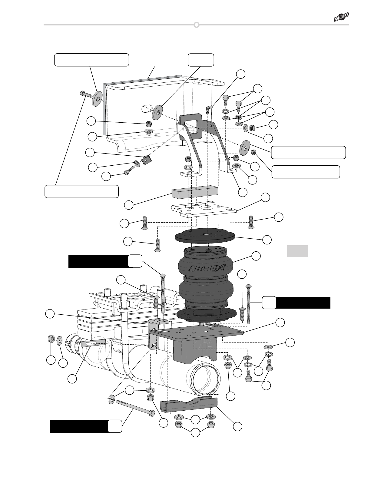
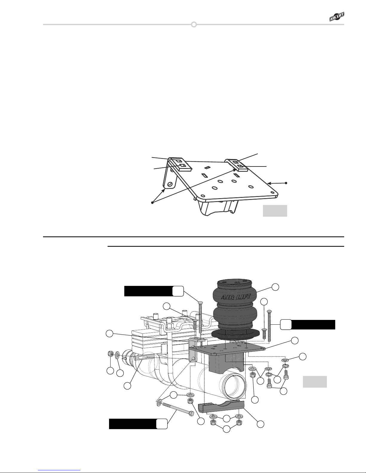
Item Part # Description ............................... Qty
A 03991 Lower Bracket.....................................2
B 07996 Upper Brace........................................1
C 07997 Upper Bracket.....................................1
D 01531 Clamp Bar...........................................2
E 10861 Spring Clamp Bar................................2
F 13966 Spacer.................................................2
G 11951 Roll Plate.............................................4
H 58437 Bellows................................................2
I 10880 Four Hole Locating Bracket ................4
J 10886 “L” Bracket ..........................................1
K 17110 3/8-16 x 5.5 Hex Head Cap Screw .....4
L 17135 1/4”-20 x 1” Hex Cap Screw................1
M 17141 3/8-16 x 2.5” Carriage Bolt..................2
N 17203 3/8-24 x 7/8” Hex Head Cap Screw ....8
O 17271 1/2”-13 x 3” Hex Cap Screw................2
P 17361 3/8-16 x 1.25” Carriage Bolt................8
Q 17387 3/8-16 x 10” Carriage Bolt...................4
Item Part # Description ............................... Qty
R 18207 1/2” Thick Flat Washer........................6
S 18419 Flat Washer #12..................................2
T 18425 1/4”-20 Nyloc Nut................................1
U 18427 3/8” Lock Washer................................8
V 18435 3/8”-16 Nyloc Nut...............................18
W 18444 3/8” Flat Washer ................................34
X 18460 1/2-13” Nyloc Nut................................2
Y 18556 3/4” Flat Washer .................................2
Z 21837 90 ˚ Swivel Air Fitting ..........................2
AA 10466 Zip Ties ...............................................6
BB 18411 5/16” Lock Washer..............................2
CC 21230 Valve Caps..........................................2
DD 21233 5/16” Hex Nut......................................2
EE 21234 Rubber Washer...................................2
FF 20086 Air Line Assembly ...............................1
GG 34924 Heat Shield Kit ....................................1
HH 17208 1/2-13 x 2” Hex Head Cap Screw .......2
HARDWARE LIST
Hardware and Tools Lists
LoadLifter 5000