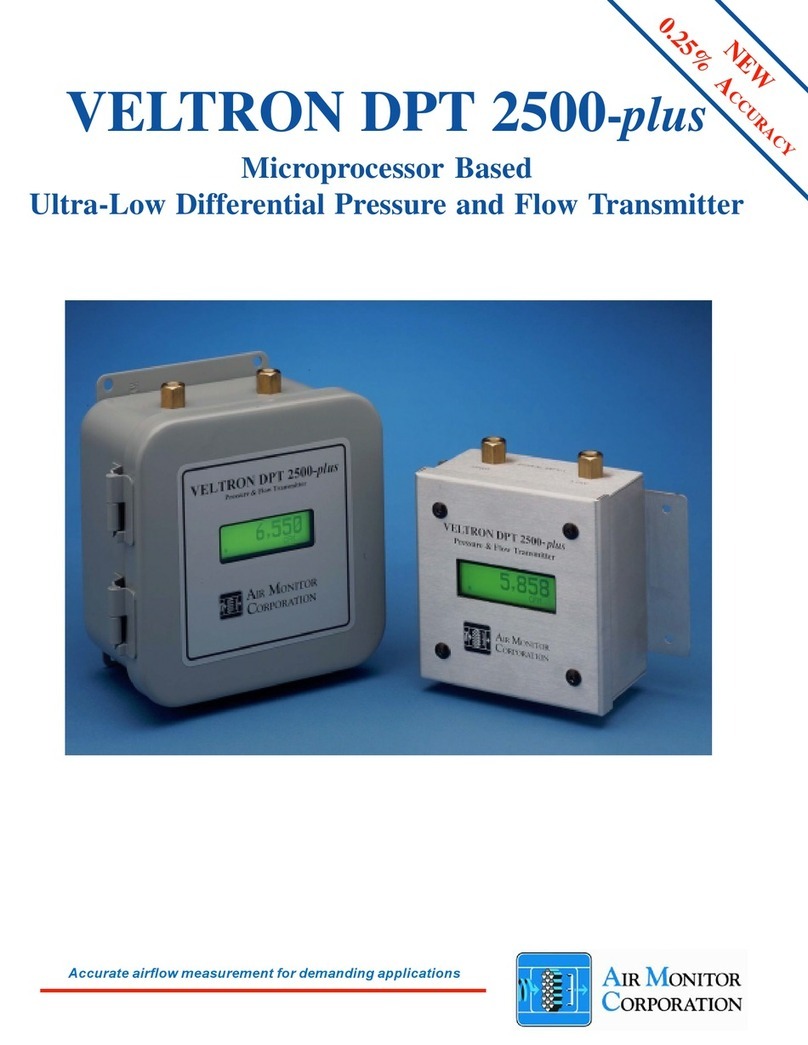
Air Monitor Corporation AMC POWER VELTRON DPT Instruction manual

Installation, Operation,
and Maintenance Manual
VELTRON DPT
Ultra-LowRange
Pressure& Flow Transmitter
Installation, Operation & Maintenance
Air Monitor Corporation provides complete
technical support between the hours of
7 a.m. and 5 p.m. PST, M-F
Contact our Service Department
Toll Free: 1-800-AIRFLOW
or fax us at 1-707-526-2825
Air Monitor Corporation
116-009-70.P65(09/18/09) VELTRONDPT-IO&MManual


VELTRON DPT
Air Monitor Corporation
116-009-70.P65(09/18/09) VELTRONDPT-IO&MManual
TABLEOFCONTENTS
INSTRUMENTWARRANTY ...................................................................................................................... i
SECTION1– GENERALINFORMATION
1.1 DESCRIPTION ................................................................................................................................1
1.2 THEORYOF OPERATION .............................................................................................................. 1
SECTION2– PERFORMANCE SPECIFICATIONS
2.1 TRANSMITTER ............................................................................................................................... 2
2.2 INDICATION..................................................................................................................................... 2
2.3 INPUT/OUTPUT ............................................................................................................................... 2
2.4 POWER .......................................................................................................................................... 2
SECTION3– FEATURES
3.1 ACCURACY .................................................................................................................................... 3
3.2 PRIMARYSIGNALNOISE FILTER.................................................................................................. 3
3.3 SQUAREROOT FUNCTION(Optional)............................................................................................ 3
3.4 CONTINUOUSDISPLAYOFPROCESS(Optional) ......................................................................... 3
3.5 HIGHTURNDOWNRATIOOPERATION .......................................................................................... 3
3.6 HAZARDOUSLOCATIONS.............................................................................................................. 3
3.7 ENCLOSURE .................................................................................................................................. 3
SECTION 4 – INSTALLATION
4.1 RECEIVINGAND INSPECTION ....................................................................................................... 4
4.2 LOCATION ...................................................................................................................................... 4
4.3 MOUNTING .................................................................................................................................. 5-6
4.4 PROCESSCONNECTIONS ......................................................................................................... 7-8
4.5 POWER/SIGNALCONNECTIONS .................................................................................................. 9
SECTION5–OPERATION
5.1 START-UP ..................................................................................................................................... 10
5.2 NORMALOPERATION.................................................................................................................. 10
5.3 SETTINGSIGNALNOISEFILTER ................................................................................................. 10
SECTION6–CALIBRATION
6.1 REQUIREDEQUIPMENT ...............................................................................................................11
6.2 PREPARATION ..............................................................................................................................11
6.3 TRANSMITTERCALIBRATION ..................................................................................................12-13
6.4 RESPANNING............................................................................................................................... 13
SECTION7– MAINTENANCE ............................................................................................................... 14
SECTION8– TROUBLESHOOTING ..................................................................................................... 15
SECTION 9 – PARTS LIST.................................................................................................................... 16
SECTION10– CUSTOMER SERVICE .................................................................................................. 17
TABLEOFCONTENTS

VELTRON DPT
Air Monitor Corporation
116-009-70.P65(09/18/09) VELTRONDPT-IO&MManual
i
INSTRUMENT WARRANTY
NOTICEOFPROPRIETARYRIGHTS
This document contains confidential technical data, including trade
secretsand proprietary information which are the sole property ofAir
MonitorCorporation. The use of said data issolelylimitedtouse as
specifiedherein. Anyotheruseis strictly prohibited without the prior
writtenconsentofAirMonitorCorporation.
INSTRUMENTWARRANTY
AirMonitorCorporation(hereinafterreferredtoas“Seller”)
warrants that at the time of shipment, products sold
pursuant to this contract will be free from defects in
materials and workmanship, and will conform to the
specifications furnished or approved in writing by Seller.
Nowarrantyisgiventhat delivered products will conform
to catalog sheets, data sheets, and the like, which are
subject to change without notice.
Seller will repair or replace, at its option, any products
listedunderthis warrantywhichisreturnedfreight prepaid
toSellerwithin the earlier of three (3)years afterstart-up
or thirty-nine (39) months after shipment that upon test
andexamination,provesdefective within the termsofthis
warranty. Listed products sold without Seller provided
start-upmustbereturnedfreightpre-paidtotheSellerfor
repair or replacement. The warranty period for any item
repairedorreplaced shall beforthetimeremaining onthe
warranty period of the original components. Purchaser
shallnotifySellerinwritingofsuch defect within sixty (60)
daysof discovery of the defect.
This warranty does not extend to any product sold by
Seller which has been the subject of misuse, neglect,
accident, damage or malfunction caused by
interconnectionwithequipmentmanufacturedbyothers,
improper installation or storage, or used in violation of
instructionsfurnishedby Seller, nor does it extend to any
product which has been repaired or altered by persons
notexpresslyapprovedbySeller. NordoesSellerwarrant
equipmentagainstnormaldeteriorationduetoenvironment;
noritemssuchaslamps,glass,andsimilaritemssubject
towearorburnoutthroughusage. Adjustmentsfor items
or equipment not manufactured by Seller shall be made
totheextentofanywarrantyofthemanufacturerorsupplier
thereof.
Seller shall not be liable for any special or consequential
damagesorforlossofdamage,directlyorindirectlyarising
from the use of the products. Seller's warranty shall be
limited to replacement of defective equipment and shall
notincludefieldremovaland installation expenses.
Thewarrantysetforthaboveisinlieuofallotherwarranties
eitherexpressorimpliedandconstitutesthefullextentof
Air Monitor Corporation’s liability to the customer, or any
otherpartyfor breach of warranty.
THEREARE NO EXPRESSWARRANTIESEXCEPTAS
SET FORTH HEREIN AND THERE ARE NO IMPLIED
WARRANTIES OF MERCHANTABILITY OF FITNESS
FOR ANY PARTICULAR PURPOSE, WHICH ARE
PARTICULARLYDISCLAIMED.

VELTRON DPT
Air Monitor Corporation
116-009-70.P65(09/18/09) VELTRONDPT-IO&MManual
1 – GENERAL INFORMATION
1.1 – DESCRIPTION
The VELTRON DPT ultra-low range pressure and flow transmitter is designed to receive signals of space or duct
pressurization and reference pressures from static pressure sensors, or signals of total and static pressure from an
airflowstationortraverseprobe(s),and convert the sensed differential pressureintoa4-20mADCcurrentoutputsignal
proportionalandlinear to thestaticorvelocitypressure. TheVELTRONDPTis packagedinaNEMAType4Xenclosure
with industry-standard process connections, and is 2-wire loop powered. An optional integral LCD digital display
provideslocal indication of the measuredprocessinappropriateengineering units (i.e IN w.c.;CFM;lb/hr; %, etc.). A
pair of test terminals exist on the output terminal board that can be used for calibration and test purposes.
1.2 – THEORY OF OPERATION
Highandlow pressure signals generated by airflow stationsand probes,or staticpressure sensorsact uponopposite
sides of a flexible diaphragm within the transducer. The differential between the two pressure signals displaces the
diaphragm; the magnitude of the displacement being measured creates an electrical DC output from the transducer.
The resulting signal representing differential pressure or velocity pressure can be "manipulated": square rooted for
velocity or flow application; scaled for units of measure and area for process output; filtered and scaled for local data
display.
1
SECTION1 –GENERALINFORMATION

VELTRON DPT
Air Monitor Corporation
116-009-70.P65(09/18/09) VELTRONDPT-IO&MManual
2
SECTION2 –PERFORMANCE SPECIFICATIONS
2 – PERFORMANCE SPECIFICATIONS
Mounting Position Effect. Zero shiftonly;corrected
throughtransmittermanualzeroing.
Span and Zero Adjustment. Via multi-turn
potentiometerslocatedinside the field wiring endcap.
Zero Elevation and Suppression. Maximum zero
elevation. 60%ofcalibratedspan.Requires an optional
bi-polartrans-ducer. Maximumzerosuppression.
100%ofcalibratedspan.
Low Pass Filter. Standard: 1.25 seconds to 98% Full
Span step. Adjustable: 0.25 to 10 seconds via
socketed resistor.
Overpressure and Static Pressure Limit. 25 psig.
Temperature Limits. –20 to 180ºF Storage; +32 to
140ºFOperating.
Humidity Limits. 0-95%RH,non-condensing.
2.1 – TRANSMITTER
Type. Differential Pressure
Ranges.Natural Full Span MinCalibrated Span
0 to 10.00 IN w.c. 0 to 4.00 IN w.c.
0 to 5.00 IN w.c. 0 to 2.00 IN w.c.
0 to 2.00 IN w.c. 0 to 0.80 IN w.c.
0 to 1.00 IN w.c. 0 to 0.40 IN w.c.
0 to 0.50 IN w.c. 0 to 0.20" IN w.c.
0 to 0.25 IN w.c. 0 to 0.10 IN w.c.
0 to 0.10 IN w.c. 0 to 0.04 IN w.c.
Accuracy. ±0.5% of Natural Full Span,includingnon-
linearity, hysteresis, deadband, and non-repeatability.
Stability. ±0.5% of Natural Full Span for six months.
Vibration Effect. ±0.05% of Natural Full Span/5G to 60
Hz.
Temperature Effect.
Zero. 0.015%of Natural Full Span/ºF.
Span. 0.015%ofNaturalFullSpan/ºF.
2.2 – INDICATION
Display. Optional3½ digit LCD.
2.3 – INPUT/OUTPUT
Input. Differentialpressure(highandlow).
Output. 4-20mADC.
2.4 – POWER
Power Supply. 14-40VDC. Twowirebasicconfiguration.
Circuit Protection. Powerinputis reverse polarity protected.

VELTRON DPT
Air Monitor Corporation
116-009-70.P65(09/18/09) VELTRONDPT-IO&MManual
3 – FEATURES
3.1 – ACCURACY
TheVELTRONDPTtransmitter is designed to maintain an accuracy of ±0.50% of Natural Full Span. Foraspanof 0 to
0.10 IN w.c., this accuracy is equivalent to an output accuracy of ±0.0005IN w.c. differential pressure or ±6.33 FPM
velocity.
3.2 – PRIMARY SIGNAL NOISE FILTER
Toeliminatebackground noiseandpulsationsfromtheflowsignal, theVELTRONDPTisequippedwithauserselectable
low pass filter.
3.3 – SQUARE ROOT FUNCTION (optional)
Whenequippedwith thesquarerootoption, theVELTRONDPTcan provideanoutputsignallineartovelocityorvolume.
3.4 – CONTINUOUS DISPLAY OF PROCESS (optional)
TheVELTRON DPT transmittercanbeoptionallyequippedwith a 3½-digitLCDdisplaytoprovidea continuous readout
of the measured process in engineering units (Inches w.c., SCFM, lbs/hr, etc.).
3.5 – HIGH TURNDOWN RATIO OPERATION
The VELTRON DPT transmitter, with its high level of accuracy, can maintain linear output signals on applications
requiringvelocityturndown of 5 to 1(equal toavelocitypressureturndownof25 to 1).
3.6 – HAZARDOUS LOCATIONS
TheVELTRON DPTtransmitterisFactoryMutualapprovedforthefollowing:
• Explosion Proof: Class 1, Division 1, Groups B, C, D.
• Dust Ignition Proof: Class II, III, Division 1, Groups E, F, G.
• Suitablefor indoor and outdoor NEMAType4X hazardouslocations.
3.7 – ENCLOSURE
TheVELTRONDPTtransmitterispackagedinaNEMAType4Xenclosurewith standardindustrialprocess connections.
3
SECTION 3 – FEATURES

VELTRON DPT
Air Monitor Corporation
116-009-70.P65(09/18/09) VELTRONDPT-IO&MManual
4
4.1 – RECEIVING AND INSPECTION
• Carefully remove the VELTRON DPTfrom the shipping container and inspect for any damage. If any damage has
occurredin transit, contactfreight carrier.
• SavetheshippingcontainerforpossiblefutureuseinreturningtheVELTRON DPTtothe factory for recalibration.
• Included in the shipping container is a Mounting Bracket Kit consisting of: two-piece mounting bracket, U-bolt, and
necessaryhardware. Ifany items are missing, contactthe Customer Service Departmentat1-800-AIRFLOW.
• ReviewtheFactory Setup Information Sheet provided separatelyandverify the W.O. # and Serial #match thoseon
theVELTRONDPT. Verifythattheconfigurationrecorded on the FactorySet-UpInformationSheetiscorrectfor your
application. Ifnot,contactAir Monitor's Customer Service Department at 1-800-AIRFLOW for further guidance.
Note: The VELTRON DPT has been configured and calibrated to customer specified parameters (see "Factory
Setup Information Sheet", and requires no additional calibration/verification prior to installation.
4.2 – LOCATION
• The VELTRONDPTis housed inaNEMA Type4Xenclosure which issuitable for outdoor locations.
• TheVELTRONDPT is Factory Mutual approvedasexplosionproof for Class I,Division1,Group B, C, andD;dust-
ignitionproofforClass II/III, Division1,GroupsE, F, and Ghazardous(classified)location,indoorand outdoor(NEMA
Type4X).
• Theambient temperature of the selected mounting location must be between32º – 140ºF. Considerationshouldbe
given to units installed in enclosures exposed to direct sunlight.
• The VELTRON DPT may be mounted in any position or attitude and is not affected by any reasonable shock or
vibration.
4 – INSTALLATION
SECTION4 – INSTALLATION

VELTRON DPT
Air Monitor Corporation
116-009-70.P65(09/18/09) VELTRONDPT-IO&MManual
5
SECTION4 – INSTALLATION
4.3 – MOUNTING
Althoughnotrequired,themostconvenientmethodformountingtheVELTRON DPTisutilizingthe included Mounting
Bracket Kit. Figure 4.1 shows how the various components are assembled, and Figure 4.2 depicts a variety of
mountingorientations.
Figure4.1
CAUTION
Do not rotate the electronics enclosure relative to the base. Internal signal tubing could
becometwistedorkinked,causingpossibletransduceroverpressurization,voidingwarranty.

VELTRON DPT
Air Monitor Corporation
116-009-70.P65(09/18/09) VELTRONDPT-IO&MManual
6
SECTION4 – INSTALLATION
4.3 – MOUNTING (con't)
If using the Mounting Bracket Kit, Figure 4.2 depicts a variety of mounting orientations.
Figure4.2
CAUTION
VELTRON DPTshould not be mountedsolelyby the
processconnectionsor electrical conduit, which donot providesufficientsupport.

VELTRON DPT
Air Monitor Corporation
116-009-70.P65(09/18/09) VELTRONDPT-IO&MManual
7
4.4 – PROCESS CONNECTIONS
TheVELTRON DPThas two 1/4"-18 FPTprocessconnections at 2-1/8" center-to-center onthebottomofthe
stainless steel base.
Figure4.3
SECTION4 – INSTALLATION

VELTRON DPT
Air Monitor Corporation
116-009-70.P65(09/18/09) VELTRONDPT-IO&MManual
8
4.4 – PROCESS CONNECTIONS (con't)
To the selected process connections, customer should install appropriate fitting required to connect process signal
tubing/pipingfromprocesssensor.
Note: Wheninstallingprocess connections, use appropriate thread lubricant/sealant.
Whenconnectingthe VELTRONDPTto an airflow measuringdevice,connectionsmustbecompletedas follows:
– HighPortonVELTRON DPTconnectstoTotalPressure from airflow measuringdevice.
– LowPorton VELTRONDPTconnectstoStaticPressure from airflow measuringdevices.
WhenconnectingVELTRON DPTforpositiveroom pressurization, connections must be completed asfollows:
– HighPorton VELTRONDPTconnects to sensor from monitored room.
– LowPortonVELTRON DPTconnectsto reference sensor.
WhenconnectingVELTRON DPTfornegative room pressurization, connections must be completed as follows:
– HighPortonVELTRON DPTconnectsto reference sensor.
– LowPorton VELTRONDPTconnectstosensorfrommonitoredroom.
Althoughanysizeoftube/pipe can be used, theresponsetimeoftheVELTRON DPTtoprocesschangeincreases with
increasingtube/pipesize or increasing tube/pipe length.
SECTION4 – INSTALLATION
CAUTION
It is extremely important that no pressure be present in signal tubing at the time
ofinstallation, and the orientation ofhighandlow pressure signal lines
ismaintainedbetween the sourceand theVELTRONDPT.

VELTRON DPT
Air Monitor Corporation
116-009-70.P65(09/18/09) VELTRONDPT-IO&MManual
9
4.5 – POWER/SIGNAL CONNECTIONS
The VELTRON DPT is a two-wire loop powered device requiring a 14-40 VDC power supply. The maximum load
resistancethatcan be driven will depend on thepower supplyvoltage (seeFigure4.4).
Figure4.4
All electrical connections are done at the terminal strip located under the "Terminal Side" cover. Wiring should be
routedthroughoneofthe 3/4-14 NPT conduit connections.
It is recommended that wiring be 14AWG to 22AWG.
ThePower/Signalwiresshouldbeconnectedto the terminals labeled± POWER INPUT inaccordancewithFigure4.5.
Figure4.5
SECTION4 – INSTALLATION

VELTRON DPT
Air Monitor Corporation
116-009-70.P65(09/18/09) VELTRONDPT-IO&MManual
10
5 – OPERATION
SECTION5 – OPERATION
The VELTRON DPT has been configured and calibrated at the Factory to customer specified parameters which are
recordedonthe VELTRONDPTFactorySetupInformation Sheet. Reviewthisinformationand verifythattheVELTRON
DPTsetup is correct forthe intendedapplication. If anyproblems or discrepanciesare detected,contactAirMonitor’s
CustomerServiceDepartmentat1-800-AIRFLOW prior to proceeding.
5.1 – START-UP
Verify process connections are correct according to Section 4.4.
Verify electrical connections are correct according to Section 4.5.
ApplypowertotheVELTRON DPTandverifyLCDdisplay (if provided) is on.
Verify output isbetween4.0and20.0mADC (4.0mAfor minimum process and 20.0mAfor maximum process).
5.2 – NORMAL OPERATION
WithStart-Up (Section 5.1)complete,theVELTRON DPTwillcontinuetooutputand display (if provided) the monitored
processwithoutanyfurtheruser interface.
5.3 – SETTING SIGNAL NOISE FILTER
IftheVELTRON DPT’soutput and display (if provided)are continuouslyfluctuatingduetoapulsating(noisy) process
signal, the user can slow the unit’s response to these fluctuations by increasing the signal noise filter.
1. Remove the terminal side cover and locate resistor R9 next to the wiring terminal strip in the Terminal Board.
2. The factory supplied value forthis resistoris90.9Kohm. To slow the unit's response time,increase theresistance
valueofR9. See Figure 5.1 for desired filtering (timeconstant) versusresistance valueof R9.
3. Remove existing resistor and install new one of increased value. Operate transmitter and observe output and
display. Continue to increase or decrease the value of R9 until desired results are obtained.
4. PerformCalibration(Section6)anytimethe filter resistor is changed.
Figure5.1

VELTRON DPT
Air Monitor Corporation
116-009-70.P65(09/18/09) VELTRONDPT-IO&MManual
11
• This Section will detail steps necessary to calibrate the VELTRON DPT.
• This Section can be accomplished with the VELTRON DPT mounted in its operating location or at a test bench in a
calibrationlab.
• Ifcalibratedatatestbench,theVELTRON DPTshouldbepositionedinthesameattitudeas in itsoperatinglocation.
6.1 – REQUIRED EQUIPMENT
1. DigitalManometer capableofreadingtothenearest 0.001” w.c.
2. DigitalMultimeter (DMM).
3. Source of clean, dry instrument air.
4. Adjustablelow pressure air regulator,suchasAirMonitor’s “Low PressureAir Source” or equal.
6.2 – PREPARATION
1. Turnpower to VELTRONDPToff.
2. Remove total and static pressure signal lines at the VELTRON DPT.
3. Removeterminalsidecover and circuit sidecoverif unit is suppliedwithdisplay.
4. Prepare test equipment as shown in Figure 6.1.
5. Turn power to VELTRONDPTon. Allow5minuteswarm-upbeforeproceeding.
Figure6.1
6 – CALIBRATION
SECTION6 – CALIBRATION

VELTRON DPT
Air Monitor Corporation
116-009-70.P65(09/18/09) VELTRONDPT-IO&MManual
6.3 – TRANSMITTER CALIBRATION
The VELTRON DPT output and optional display will be calibrated for minimum and maximum full scale differential
pressure.
6.3.1 Forunitswithunipolarpositiveornegativedifferentialpressurespans.
1. At the Terminal board, connect DMM, set to read to the nearest 0.001VDC, across test points TP0 GND
(black) and TP1 XMIT (brown). See Figure 4.5.
2. With zero input pressure to theVELTRONDPT,verify the DMM reads 0.000 ±0.001VDC. Ifadjustment is
required,adjustXMIT ZERO (R5 onTerminalboard)asneeded.
3. VerifytheLCDdisplay(if so equipped) reads 000±001. Adjustasnecessaryusing ZERO(R9onDisplay
board,seeFigure6.2).
Figure6.2
4. Connect DMM, set to read to the nearest 0.01mADC, to terminals ±TEST OUTPUT on Terminal board.
DMMshouldread 4.00 ±0.01mADC. Adjust as necessary using OUTPUT ZERO (R4onTerminalboard).
5. Apply input pressure (as read on manometer) to the High port of the VELTRON DPT. Adjust pressure
accordingtothefollowing:
– ForPositivedifferential pressurespans. Themaximumcalibratedspan valueasindicatedonthe Factory
Set-UpInformationSheet.
– For Negative differential pressure spans. The positive equivalent of the maximum negative calibrated
spanvalueas indicated on the Factory Set-Up Information Sheet.
6. Verify DMM at ±TEST OUTPUT terminals read 20.00 ±0.01mADC. Adjust as necessary using XMIT
SPAN(R3 onTerminal board).
7. VerifytheLCDdisplay(ifsoequipped)readsthedesiredfullscalevalue. Adjustas necessary using SPAN
(R1onDisplayboard)untildesiredreading±001isachieved.
8. Repeat Steps 1 through 7 as necessary until no further adjustments are required to either zero or span.
9. Remove test equipment and replace terminal side and circuit side covers, taking care to ensure proper
seal.
12
SECTION6 – CALIBRATION

VELTRON DPT
Air Monitor Corporation
116-009-70.P65(09/18/09) VELTRONDPT-IO&MManual
6.3 – TRANSMITTER CALIBRATION (con't)
The VELTRON DPT output and optional display will be calibrated for minimum and maximum full scale differential
pressure.
6.3.2 For units with Bi-Polar Spans
1. At the Terminal board connect DMM, set to read to the nearest 0.001VDC, across test points TP0 GND
(black) and TP1 XMIT 1 (brown). See Figure 4.5.
2. Applyinputpressure(asread on manometer) to theLowportoftheVELTRONDPT. Adjust pressure to the
positiveequivalentoftheminimum(negative)calibratedspanvalueasindicatedontheFactorySet-UpInformation
Sheet.
3. Verify the DMM reads 0.000 ±0.001 VDC. If adjustment is required, adjust XMIT ZERO (R5 on Terminal
board)asneeded.
4. Verify the LCD display (if so equipped) reads the desired minimum process value. Adjust as necessary
usingZERO (R9 on Display board, seeFigure 6.2) untildesired reading ±001 isachieved.
5. Connect DMM, set to read to the nearest 0.01mADC, to terminals ±TEST OUTPUT on Terminal board.
DMMshouldread 4.00 ±0.01mADC. Adjust as necessary using OUTPUT ZERO (R4onTerminalboard).
6. Disconnect pressure input from Low port and connect to the High port.
7 Adjustinputpressureto the maximum (positive) calibrated span value asindicated onthe FactorySet-Up
InformationSheet.
8. Verify DMM at ±TEST OUTPUT terminals reads 20.00 ±0.01mADC. Adjust as necessary using XMIT
SPAN(R3 onTerminal board),
9. Verify the LCD display (if so equipped) reads the desired maximum process value. Adjust as necessary
usingSPAN (R1 on Display board) until desiredreading ±001 is achieved.
10. Repeat Steps 1 through 9 as necessary until no further adjustments are required to either zero or span.
11. Remove test equipment and replace terminal side and circuit side covers, taking care to ensure proper
seal. 6.4 – RESPANNING
Thecalibrated spanofthe VELTRONDPTcan be adjustedbetween40%and 100% of itsnaturalspan(see Factory
Set-UpSheetforthe natural span).
6.4.1 Determine if the new desired calibrated span is within 40% to 100% of the natural span.
– If it is, continue with this procedure.
– If it is not, contact theAir Monitor Service Department regarding replacing the transducer.
6.4.2 Follow Steps 1 through 5 of Section 6.3.1, but adjust the input pressure to the new desired calibrated span.
6.4.3 Whenperforming Step 6 ofSection6.3.1,if R3 (XMITSPAN) willnotadjust output to 20.00mADC,thenR1
(socketedresistoronTerminalboard) will need to be replaced.
TheapproximatevalueofR1neededto obtain the desired calibrated spancanbecalculatedwiththefollowing
formulas; For a 0.05" w.c. natural span: R1 =
For allother naturalspans: R1 =
Selectastandard resistor nearest in value to thevalue calculatedabove.
AfterR1hasbeenreplacedwiththeappropriatevalue,repeatallofSection6.3.1toensurepropercalibration.
13
SECTION6 – CALIBRATION
CalibratedSpan
0.05"w.c. x100
CalibratedSpan
Natural Span in IN w.c. x200

VELTRON DPT
Air Monitor Corporation
116-009-70.P65(09/18/09) VELTRONDPT-IO&MManual
14
7 – MAINTENANCE
SECTION7 – MAINTENANCE
The VELTRON DPT is a solid state device having no mechanical parts requiring special periodic maintenance. The
following maintenance steps are not requirements, but guidelines for establishing a maintenance program for your
specific installation.
Operatingexperience should be used to setfrequencyofspecifictypes of maintenance.
7.1 – CLEANLINESS
– Verifycondensation (or other sources of liquids) arenot presentinside theVELTRONDPT.
7.2 – MECHANICAL
– Verifypressure signal connections are secure.
– Inspect pressure signal lines for any cracks or leaks.
– Verify mounting hardware is secure.
7.3 – ELECTRICAL
– Periodicallyinspectall wiring to the VELTRONDPTfor goodconnections andabsenceofcorrosion.
7.4 – CALIBRATION
– VELTRON DPTshouldhavecalibrationverifiedannuallyasaminimum.

VELTRON DPT
Air Monitor Corporation
116-009-70.P65(09/18/09) VELTRONDPT-IO&MManual
15
8 – TROUBLESHOOTING
SECTION 8 – TROUBLESHOOTING
PersonnelshouldbefamiliarwiththeoperationoftheVELTRONDPTbeforeperformingany troubleshooting.
Problem
No output and no display (if
so equipped).
Output is present, but no
display.
Output and display do not
change with change in
process input.
Solution
–Verify input power connections (see Figure 4.5).
–Verify input power is present and between 14-40VDC.
–Replace Power Supply Board.
–Replaced LCD Display Board.
–Verify pressure signal lines are connected correctly.
–Verify differential pressure at input fittings.
–Verify internal signal tubing was not blown off transducer by excessive pressure (see
drawings in Section 9).
–Using a DMM set for DC voltage, measure between TP0-GND (black) and pin 4-XDCR of
P2 on Terminal Board (see Figure 4.5).
With full positive differential pressure applied, DMM should read 0.7 ± 0.3VDC.
If DMM does not read 0.7 ± 0.3VDC, replaced Transducer Board.
If DMM reads correctly, measure DC voltage between TP0-GND (black) and TP1-XMIT
(brown) on Terminal Board.
With full differential pressure still applied, DMM should read 0.7 ± 0.3VDC.
If DMM does not read 0.7 ± 0.3VDC, replace Terminal Board.
If DMM reads correctly, measure DC voltage between TP0-GND (black) and Pin 5-XMIT2 of
P2 on Terminal Board (see Figure 4.5).
With full differential pressure still applied, DMM should read 0.7 ± 0.3VDC.
If DMM does not read 0.7 ± 0.3VDC, replace Power Supply Board.
If DMM reads correctly, replace Terminal Board.
Ifafterfollowing the Troubleshootingsteps the VELTRONDPTcontinues to operateimproperly,
contacttheService Department for further assistance (seeSection10).

VELTRON DPT
Air Monitor Corporation
116-009-70.P65(09/18/09) VELTRONDPT-IO&MManual
16
9 – PARTS LIST
SECTION 9 – PARTS LIST
• Thefollowingdrawingwithpartnumberslistcomponents of the VELTRONDPTthat are easilyreplaced by the user.
• To inquire about priceand availableofaspecificpartnumber,pleasecontactthe Customer ServiceDepartment at:
Phone– 1-707-544-2706 Fax–707-526-2825
1-800-AIRFLOW
• WhencontactingtheCustomer Service Departmentaboutparts,pleasehavetheapplicable Factory Set-UpInforma-
tionsheetavailablefor reference.
Table of contents
Other Air Monitor Corporation Transmitter manuals
Popular Transmitter manuals by other brands

Greystone Energy Systems
Greystone Energy Systems CDD4 installation manual

HETRONIC
HETRONIC NOVA Series user manual

E+E Elektronik
E+E Elektronik EE22 Series manual

Extron electronics
Extron electronics XTP T VGA user guide

AKG
AKG PT 4500 User instructions

Vestamatic
Vestamatic VestaFunk MS16 Series Installation and operating instructions