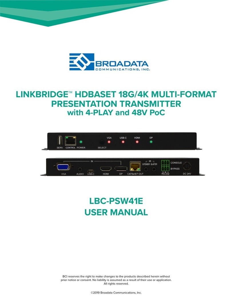
Broadata Communications LINKBRIDGE LBC-HDV-T User manual

LINKBRIDGE™ HDBASET
HDMI/DISPLAYPORT/VGA
TRANSMITTER WITH INTEGRATED
CONTROL PROCESSOR
BCI reserves the right to make changes to the products described herein without
prior notice or consent. No liability is assumed as a result of their use or application.
All rights reserved.
©2019 Broadata Communications, Inc.
LBC-HDV-T-ICP / LBC-HDV-T
USER MANUAL

HDBaseT HDMI/DisplayPort/VGA Transmitter with ICP User Manual (LBC-HDV-T-ICP)
SAFETY INSTRUCTIONS AND COMPLIANCE DECLARATION
PLEASE OBSERVE THE FOLLOWING SAFETY PRECAUTIONS
SURGE PROTECTION DEVICE RECOMMENDED
This product contains sensitive electrical components that may be damaged by
electrical spikes,surges,electric shock,lightning strikes, etc. Use of surge proctection
system is highly recommended in order to protect and extend the life of your
equipment.

HDBaseT HDMI/DisplayPort/VGA Transmitter with ICP User Manual (LBC-HDV-T / LBC-HDV-T-ICP)
SAFETY INFORMATION
Do not use this device near water/liquids. This device should not be exposed to dripping and
splashing or liquids.
Clean only with dry cloth.
Do not use solvents such as paint thinners and acetone to clean external casing. Such
agents will remove any labels on the device.
Do not block any ventilation openings.
Do not install near any sources of intense heat such as radiation, boilers, or other equipment
that produce heat
Not intended for use/storage in close proximity of critical medical supplies such as those that
might come into direct contact with patients or medical sta.
Protect the power cord from being pinched or damaged at receptacles and the point of exit
from the device.
Only use attachment /accessories specified by manufacturer. If you have any questions
about the compatibility of an accessory, contact your dealer.
In case liquid spillage on device, unplug mains power cord and contact your dealer. Continu-
ous use in this case may result in fire or electric shock.
To reduce the risk of electric shock, do not touch connectors with wet hand.
Only power with the marked voltage on the device. Any other voltage can cause fire or elec-
tric shock.
Do not use the device if an abnormality occurs. If any smoke or odor becomes apparent, un-
plug the power cord and contact your dealer. Do not try to repair the device yourself.
Avoid using physically damaged devices. If your device metal housing is seriously physically
damaged, the internal components may function abnormally. Contact your dealer.
Do not install the device in an area heavy with dust or constant high humidity. Operating the
device in this case may result in fire or electric shock.
Only use supplied power supply. For a list of other compatible power supplies, contact your
dealer.
Install this device in a secure location where it cannot be easily pushed or knocked over.

HDBaseT HDMI/DisplayPort/VGA Transmitter with ICP User Manual (LBC-HDV-T / LBC-HDV-T-ICP)
TABLE OF CONTENTS
PRODUCT DESCRIPTION
OPERATION CONTROL AND FUNCTIONS
FRONT/REAR PANEL
CONNECTOR PIN OUT ASSIGNMENT
CONFIGURATION LBCHDVT
API COMMANDS
CONFIGURATION LBCHDVTICP
KEYPAD CONTROL
TOUCH PANEL
ALEXA VOICE
CONFIGURATION
SPECIFICATIONS
MAINTENANCE AND TROUBLESHOOTING
SERVICE PROCEDURE
REPLACEMENT POLICY
RETURN AND REPAIR SERVICE
LIMITED WARRANTY
5
6
6
9
10
15
17
18
22
29
37
38
39
40
40
40
41
1.0
2.0
2.1
3.0
4.0
4.1
4.2
5.0
5.1
5.2
5.3
6.0
7.0
8.0
9.0
10.0
11.0
12.0

HDBaseT HDMI/DisplayPort/VGA Transmitter with ICP User Manual (LBC-HDV-T / LBC-HDV-T-ICP)
5
PRODUCT DESCRIPTION
The LBC-HDV-T is a multi-format switcher with HDMI, VGA and DisplayPort inputs
to HDBT output. The audio port is independent and could be embedded into any
of the video signals and send it to the far end. The product supports webserver
and can be controlled by the button, LAN, RS-232, contact closure, IR and RS-232
can pass through.
Features include:
• Switch and extend HDMI, DisplayPort or VGA signals up to 70 meters over CAT-
5e/6
• HDTV video resolutions up to 720p/1080i/1080p@60Hz or 1920x1200@60Hz,
as well as Ultra HD (4K2K@30Hz)
• Fully uncompressed video with embedded audio provides zero loss of quality
• Selectable manual or auto-switching between HDMI, DisplayPort and VGA
inputs
• Webserver for monitoring and configuation
• Manual switching through front-panel button, contact closure, RS-232 or
webserver
• Video/Audio+Data over 1 CAT-5e/6 with true DDC/EDID/HDCP transmission
• Compatible with our LBH/LBC Series products

6
HDBaseT HDMI/DisplayPort/VGA Transmitter with ICP User Manual (LBC-HDV-T / LBC-HDV-T-ICP)
OPERATION CONTROL AND FUNCTIONS
FRONT PANEL
1
PWR: Solid red when powered on.
HDMI: LED solid when HDCP is active, flashing when HDCP is not active.
LINK: Flashing when HDBT connected without video signal, solid when video
presented.
D: LED solid when DP selected, flashing when signal presented, o means no
input signal.
H: LED solid when HDMI selected, flashing when signal presented, o means no
input signal.
V: LED solid when VGA selected, flashing when signal presented, o means no
input signal.
Select: Button for switching input signal.
1
2
3
4
4
5
6
7
HDMI
D
H
V
PWR LINK
SELECT
2
346 7

HDBaseT HDMI/DisplayPort/VGA Transmitter with ICP User Manual (LBC-HDV-T / LBC-HDV-T-ICP)
7
OPERATION CONTROL AND FUNCTIONS
BACK PANEL
PWR: Solid red when powered on.
HDMI: LED solid when HDCP is active, flashing when HDCP is not active.
LINK: Flashing when HDBT connected without video signal, solid when video
presented.
D: LED solid when DP selected, flashing when signal presented, o means no
input signal.
H: LED solid when HDMI selected, flashing when signal presented, o means no
input signal.
V: LED solid when VGA selected, flashing when signal presented, o means no
input signal.
Select: Button for switching input signal.
LV LH
TX RX
IN
OUT
AUD
HDMI
DP
VGA
D H V LD
LAN
HDBT
24V DC
Power: 24V DC Power.
HDBT Out: HDBT output.
DP: DisplayPort input.
HDMI: HDMI input.
VGA: VGA input.
AUD: Independent audio input
LAN: LAN for local control or web serve access
Phoenix Port: RS-232 and Contact Closure with LED indicator
8
9
10
11
12
13
14
15
810
911 12 13 14 15

8
HDBaseT HDMI/DisplayPort/VGA Transmitter with ICP User Manual (LBC-HDV-T / LBC-HDV-T-ICP)
CONFIGURATION
DC POWER CONNECTIONw ready to power up the LBC-HDV-T and set up your
network connection. In order to make sure that you have a proper installation, please
observe the following:
1. Your AC jack has power.
2. The 24VDC power supply is working.
3. Your electrical system has proper grounding (this ensures that your power supply
does not suer from voltage variations).
4. Power Surge Protection. This is optional, but highly recommended. A UPS system
provides voltage regularity as well as prevents spikes from occurring, thus
protecting your LBC-HDV-T from sensitive voltage conditions.
The LBC-HDV-T derives power from an external 24VDC power supply. This power
supply is a wall mounted AC/DC adapter, 100-240 VAC, 50-60 Hz, at 1A. This power
supply comes standard for the LBC-HDV-T unless otherwise specified.
If you have any problems or concerns, regarding the installation, make sure that you
have taken the proper steps to ensure a proper power connection. Otherwise, feel free
to contact us for any questions you may have.
CLICK ON THE
EDIT SYMBOL TO
EDIT COMMAND
SETTINGS. UP/
DOWN ARROWS
ARE TO MOVE THE
COMMAND UP OR
DOWN AND DE

HDBaseT HDMI/DisplayPort/VGA Transmitter with ICP User Manual (LBC-HDV-T / LBC-HDV-T-ICP)
9
CONNECTOR PINOUT ASSIGNMENT
BUTTON CON
FIGURATION
ON THE TOP MENU
BAR CLICK ON CUS
TOMIZE AND THEN
CLICK ON 8/16
BUTTON KEYPAD.
PHOENIX CONTACT CONNECTIONS
CLICK ON THE
EDIT SYMBOL TO
EDIT COMMAND
SETTINGS. UP/
DOWN ARROWS
ARE TO MOVE THE
COMMAND UP OR
DOWN AND DE
D: DP Input
H: HDMI Input
V: VGA Input
LD: LED indicator for DP
LV: LED indicator for VGA
LH: LED indicator for HDMI
TX: RS-232 Tx
RX: RS-232 Rx
GND: Ground
GND
GND
V
H
LD
D
TX
LH
LV
TX RX LV LH
D H V LD
RX

10
HDBaseT HDMI/DisplayPort/VGA Transmitter with ICP User Manual (LBC-HDV-T / LBC-HDV-T-ICP)
CONFIGURATION- LBC-HDV-T
This section describes configuration of the standard version of the LBC-HDV-T.
WEB SERVER
The factory default IP: 192.168.2.175
Note: BCI product configuration program can be used to discover unit’s IP address.
To access the product web server, user can direct connect the PC LAN port to the
LBC-HDV-T LAN port with a straight RJ-45 cable. After making the connection, go to
network connection of the PC and revise the IP property to static IP as below. Once
done, open a web browser and enter the 192.168.2.175 to access the web server.
For the LBC-HDV-T connection to the local area network, please update the LBC-
HDV-T IP to match the LAN network setting from the web server.
For example, if the LAN IP is set as 192.168.2.xxx. Once the IP is set, then you can
access the device from an PC in the same network.

HDBaseT HDMI/DisplayPort/VGA Transmitter with ICP User Manual (LBC-HDV-T / LBC-HDV-T-ICP)
11
CONFIGURATION- LBC-HDV-T
INPUT/OUTPUT CONFIGURATION
This page provides the switching, connection input signal information, and the HDBT
output connection status.
AV Inputs: Select to switch the input.
Auto Switch Video: If checked, the device is set in auto switching mode rather than
manual mode.
External Audio: If checked, the 3.5mm audio input is embedded to the input video.
Input Config: Input port information.
Output Config: HDBT connection status.
Active Input: Showing the input signal format and resolution.
Active Output: Showing output signal format and resolution.
HDCP Unauthorized: When checked, LBC-HDV-T will request no HDCP compliant source.

12
HDBaseT HDMI/DisplayPort/VGA Transmitter with ICP User Manual (LBC-HDV-T / LBC-HDV-T-ICP)
CONFIGURATION- LBC-HDV-T
CLICK ON EXTEN
SION MACRO TO
EXECUTE/EDIT UP
TO 8 MORE MAC
RO ACTIONS,
EDID MANAGEMENT
This page provides switching and EDID management.
Follow Output: EDID from display.
Broadata EDID: Internal preload EDID

HDBaseT HDMI/DisplayPort/VGA Transmitter with ICP User Manual (LBC-HDV-T / LBC-HDV-T-ICP)
13
CONFIGURATION- LBC-HDV-T
RS-232 CONTROL CONFIGURATION
RS-232: Local RS-232 setting to control the LBC-HDV-T.
HDBT RS-232: Set the far end RS-232 baud rate.
RS-232 Preset
Command 1: When detecting active signal, sends the RS-232 command in the
preset timing.
Command 2: When no active signal present, sends the command in the preset
timing.
Button: Press and hold the front panel button for 3-5 seconds, sends the
preset
command.
To set the preset RS-232, click the program button to program the code to the unit.
Note: See Appendix A for RS-232 Command Table.

14
HDBaseT HDMI/DisplayPort/VGA Transmitter with ICP User Manual (LBC-HDV-T / LBC-HDV-T-ICP)
CONFIGURATION- LBC-HDV-T
SYSTEM
System and firmware information. User can modify the IP setting on this page.
Remember to click on Apply for the changes.

HDBaseT HDMI/DisplayPort/VGA Transmitter with ICP User Manual (LBC-HDV-T / LBC-HDV-T-ICP)
15
API COMMANDS
Input Select >C
Syntax Descripon
>C<param>to1 Selects video inputs
Parameter Descripon Range
<param> Input selecon number 1 VGA Select
2 HDMI Select
3 DP Select
Command Example Command Response Funcon
>C1to1 <C1to1 Change input to HDMI
Input Switching Mode >M
Syntax Descripon
>M<param> Selects input switching mode
Parameter Descripon Range
<param> Input selecon mode number 0 Manual Mode
1 Auto Mode
Command Example Command Response Funcon
>M0 <M0 Change input switching mode
to Manual
Audio Mode >A
Syntax Descripon
>A<param> Selects audio output source
Parameter Descripon Range
<param> Input selecon mode number 0 Output audio comes from
video
1 Output audio comes from
3.5mm Audio Jack
Command Example Command Response Funcon
>A1 <A1 Output audio comes from
3.5mm Audio Jack

16
HDBaseT HDMI/DisplayPort/VGA Transmitter with ICP User Manual (LBC-HDV-T / LBC-HDV-T-ICP)
API COMMANDS
Query Informaon
Syntax Descripon
#<param> Queries informaon
Parameter Descripon Range
<param> Input selecon
mode number
C Query the selected video input
R Query output resoluon
MBaud Query the RS232 baud rate
MDBits Query RS232 data bit seng
MSBits Query RS232 stop bit seng
Mparity Query RS232 parity bit seng
DHCP Query IP mode
IP Query IP address
Mask Query IP mask
Gate Query gateway address
Tcp Port Query TCP port used
Help Return list of commands
Command Example Command Response Funcon
#IP IP:192.168.2.175 Returns IP address

HDBaseT HDMI/DisplayPort/VGA Transmitter with ICP User Manual (LBC-HDV-T / LBC-HDV-T-ICP)
17
CONFIGURATION- LBC-HDV-T-ICP
LBC-HDV-T-ICP CONNECTIONS
The LBC-HDV-T-ICP is programmed with a special firmware that allows it to easily
integrate with the LBC-H/O-R-ICP. Pairing the LBC-HDV-T-ICP with the LBC-H/O-R-ICP
supports the following features:
- Video input selection using 8-button keypad, touch panel or voice control.
- Automation triggered by video detect
- Web server of standard LBC-HDV-T is replaced by LBC-H/O-R-ICP web
server
- Serial and Telnet API provided by LBC-H/O-R-ICP Input Select >C
Syntax Description
>C<param>to1 Selects video inputs
Parameter Description Range
Figure A
LB-KP8E-ICP
LBC-HDV-T-ICP LBC-H/O-R-ICP
Connect one end of the Cat-x cable into the LBC-HDV-T-ICP HDBT port and the other
end into the LBC-H/O-R-ICP Cat-x In port. The LBC-H/O-R-ICP provides power to the
LBC-HDV-T-ICP over the HDBT connection, so the LBC-HDV-T-ICP does not need any
external power. Apply power to the LBC-H/O-R-ICP.

18
HDBaseT HDMI/DisplayPort/VGA Transmitter with ICP User Manual (LBC-HDV-T / LBC-HDV-T-ICP)
KEYPAD CONTROL
THE BACKGROUND
LIGHT BAR ALLOWS
USER TO INSTANT-
LY CHANGE THE
LEDS LIGHTING
PERCENTAGE
BASED ON THE
ORIGNIAL ILLUMI-
LBC-H/O-R-ICP Web GUI
After the LBC-H/O-R-ICP is powered up with the LBC-HDV-T-ICP connected, go to the
Configure System page of the LBC-H/O-R-ICP web GUI (See LBC-H/O-R-ICP User Manual
for web GUI details). The Tx Unit status should change to LBC-HDV-T-ICP connected,
indicating that the LBC-HDV-T-ICP has been connected successfully.
LBC-HDV-T-ICP Input Control
The following options are available for input control:
- 8-button keypad
- Touch panel display
- Voice control using Alexa
8-Button Keypad Control
The following section provides instructions on how to configure an 8-button keypad (LB-
KP8) for controlling the LBC-HDV-T-ICP input selection.
Connect an LB-KP8 to the LBC-H/O-R-ICP (See LB-KP8 User Manual for details). In the LBC-
H/O-R-ICP web GUI, go to the top menu bar. Click on Configure and then click on System.
The Configure System page will be shown. In the System panel make sure that the Keypad
Type selected is 8 button keypad.

HDBaseT HDMI/DisplayPort/VGA Transmitter with ICP User Manual (LBC-HDV-T / LBC-HDV-T-ICP)
19
KEYPAD CONTROL
THE BACKGROUND
LIGHT BAR ALLOWS
USER TO INSTANT-
LY CHANGE THE
LEDS LIGHTING
PERCENTAGE
BASED ON THE
ORIGNIAL ILLUMI-
On the top menu bar click on Keypad. The virtual 8 button keypad page shown below will
be loaded. Each button on the virtual keypad corresponds to a button on the LB-KP8. By
default buttons are not configured and labeled F1 to F8.
Button Configuration
On the top menu bar click on Customize and then click on 8/16 Button Keypad. The
following Button Keypad Definition page will be loaded.

20
HDBaseT HDMI/DisplayPort/VGA Transmitter with ICP User Manual (LBC-HDV-T / LBC-HDV-T-ICP)
KEYPAD CONTROL
THE BACKGROUND
LIGHT BAR ALLOWS
USER TO INSTANT-
LY CHANGE THE
LEDS LIGHTING
PERCENTAGE
BASED ON THE
ORIGNIAL ILLUMI-
This page configures each button’s operating mode and assigns an action(s) to a button.
Each button can operate as a Standard button or a Toggle button, which has two states,
Press and Release. A single action or multiple actions can be assigned to a button. An
action can be a native control type such as Relay, Video Control or Audio Control or an
external control type such as RS-232, IR or Telnet.
Follow the instructions below to configure 3 buttons to control the LBC-HDV-T-ICP input
selection using the Video Control actions.
The following configuration sets button, F1, to select the HDMI input.
1. In the Edit Button drop down menu, select F1.
2. In the Label field type in HDMI.
3. In the Mode drop down menu, select Standard.
4. In the Action Number drop down menu, select Action 1.
5. In Spacing field enter 0.0.
6. In the Action Type drop down menu, select Video Control.
7. In the Action drop down menu, select Input HDMI.
8. Click on Submit Changes button.
The following configuration sets button, F2, to select the DisplayPort input.
1. In the Edit Button drop down menu, select F2.
2. In the Label field type in DP.
3. In the Mode drop down menu, select Standard.
4. In the Action Number drop down menu, select Action 1.
5. In Spacing field enter 0.0.
6. In the Action Type drop down menu, select Video Control.
7. In the Action drop down menu, select Input DP.
8. Click on Submit Changes button.
This manual suits for next models
1
Table of contents
Other Broadata Communications Transmitter manuals
Popular Transmitter manuals by other brands

Evikon
Evikon PluraSens E2648-N2O user manual

Siemens
Siemens SITRANS TH Series Compact operating instructions

Intec Controls
Intec Controls MSR PolyGard AT-1195 V3 user manual

Sennheiser
Sennheiser AC 3200-II High Gain instruction manual

Viatran
Viatran 553 Installation data manual

Endress+Hauser
Endress+Hauser deltabar S PMD 25 K operating instructions