AUTEC Air LK6 User manual

Original instructions
AIR SERIES
Part C: LK6 and LK8 transmitting units
INDEX
1 Description ............................................................................................................ 2
2 Technical data ....................................................................................................... 3
3 Technical data sheet ............................................................................................. 3
4 Plates ..................................................................................................................... 4
4.1 Plates on LK6 and LK8 units in a radio remote control ..................................... 4
5 Light signals .......................................................................................................... 5
6 General operating instructions ............................................................................ 7
6.1 Starting up the radio remote control ................................................................. 7
6.2 Command activation ........................................................................................ 9
6.3 Data Feedback Function .................................................................................. 9
6.4 Radio link interruption ...................................................................................... 9
6.5 Transmittingunitautomaticswitcho .............................................................. 9
6.6 Switchingothetransmittingunit................................................................... 10
7 Operation ............................................................................................................. 10
7.1 Battery ........................................................................................................... 10
7.2 ID internal tx memory ..................................................................................... 11
7.3 Power keyswitch ............................................................................................ 11
7.4 START pushbutton ........................................................................................ 13
7.5 FUNCTION pushbutton .................................................................................. 13
7.6 STOP pushbutton .......................................................................................... 13
8 Malfunction signalled by the transmitting unit ................................................. 14
AUTEC LILK6E00-01
2
LILK6E00-01
Description
AUTEC - Air series
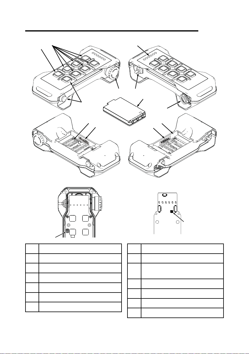
1 Description
A
B
C
DEFG
H
J
K
L
M
N
P
ACommand pushbuttons
BFUNCTION pushbutton
CSTART pushbutton
DTechnical data plate
ERadioremotecontrolidenticationplate
FTransmittingunitidenticationplate
GBattery housing
HPower keyswitch (if present)
JBattery
KActuator (selector, pushbutton) (if
present)
LSTOP pushbutton
MLED
NDIP switches
PConnector for "ID internal tx memory"

AUTEC - Air series
Technical data 3
LILK6E00-01
2 Technical data
Power supply (battery MHM03) .............................................................................. 3.6V
Power supply (battery LPM01) ............................................................................... 3.7V
Antenna .................................................................................................................. internal
Housing material .......................................................................................... PA 6 (20%fg)
Protection degree ....................................................................................... IP65 (NEMA 4)
Dimensions .................................................................. 201x85x49mm (7.91x3.35x1.92In)
Weight ....................................................................................................... 380g (0.837Lb)
Run time at 20°C (68°F):
- with battery MHM03 .................................................................................................... >8h
- with battery LPM01 ................................................................................................... >16h
3 Technical data sheet
Thetechnicaldatasheetcontainsthetransmittingunitcongurationandshowsthematching
between commands sent and machine functions/movements. It also contains the wiring
diagram showing the connection between the receiving unit and the machine.
Eachtechnicaldatasheetmustbelledin,checkedandsignedbytheinstaller,whois
responsible for a correct wiring.
A technical data sheet must always be kept toghether with this manual (always keep a copy
of the technical data sheet when it is used for administrative purposes).
The wiring of the receiving unit outputs must always reect the wiring
indicated in the technical data sheet.

4
LILK6E00-01
Plates
AUTEC - Air series
4 Plates
4.1 Plates on LK6 and LK8 units in a radio remote control
Plate Position Content
radio remote control
identication plate
Key ID 0-1 (if present).
Radio remote control
serial number (S/N).
Battery housing (if the “ID internal tx
memory” is present).
transmitting unit
identication plate Battery housing.
Manufacturing year, bar
code and transmitting
unitidenticationnumber
(TU ID).
technical data plate Battery housing.
MODEL, TYPE and
main transmitting unit
technical data, marking
and possible radio remote
control marks.

AUTEC - Air series
Light signals 5
LILK6E00-01
5 Light signals
In LK6 and LK8 transmitting units, a green LED [B] and a red LED [A] are always available,
and they provide information regarding the radio remote control.
ARed LED
BGreen LED
CLEDs for Data
Feedback function
The green LED [B] … Meaning
…is o. Thetransmittingunitisswitchedo.
... is steady on. The transmitting and receiving unit do not communicate.
… blinks fast.
The transmitting and receiving unit communicate. It is only
possible to send commands after pressing the START
pushbutton.
… blinks slowly (one blink per
second). It is possible to send commands.
The red LED [A]… Meaning
…is o. The transmitting unit works correctly.
... is steady on. At start-up, the STOP pushbutton is pressed or damaged.
... blinks twice per second. At least one of the commands that were checked at start-
up is enabled or damaged (see technical data sheet).
... blinks three times per second. Atstart-up,thebatteryisat.
... is steady on for 2s. The transmitting unit does not work correctly.
… blinks slowly (one blink per
second). The battery has less than 1h run time.
... blinks fast. The battery has a 10min run time.

6
LILK6E00-01
Light signals
AUTEC - Air series
LEDs … Meaning
… the green [B] and red [A] LEDs
are steady on
A wrong "Key ID 0-1" or "ID internal tx memory" has been
inserted in the transmitting unit, or this is a "BACK-UP
UNIT".
…the green [B] and red [A] LEDs
blink 3 times per second during
start up...
The “Key ID 0-1” is damaged or the “ID internal tx
memory” is damaged or not present.
... the green [B] and red [A] LEDs
blink alternately.
30 s left before the transmitting unit automatically switches
o.
The green LED [B] blinks and the
red LED [A] is steady during start
up.
The UNPAIR procedure has been performed.
See paragraph 6.3 to check the meaning of LEDs for Data Feedback function [C].

AUTEC - Air series
General operating instructions 7
LILK6E00-01
6 General operating instructions
6.1 Starting up the radio remote control
Starting up the radio remote control consists in establishing a radio link between the transmitting
unit and the receiving unit.
As required by standards IEC 60204-1 and IEC 60204-32, non authorised
use of the machine must be prevented.
The power keyswitch and/or the PIN CODE used for start up, make the radio
remote control compliant with such requirement.
If the transmitting unit does not have a power keyswitch, the radio remote control start up is
protected by PIN CODE.
On the contrary, when the transmitting unit needs a power keyswitch, radio remote control
start up is protected by the power keyswitch itself. If the risk assessment requires further
protection of the radio remote control start up, the PIN CODE may be activated.
The PIN CODE consists of a sequence of commands to be carried out by activating the
corresponding actuators during start up. The radio remote control will start up only with the
correct sequence.
Commands activated while typing the PIN CODE are not sent to the machine.
The procedure to enable and modify a PIN CODE is provided in the document “Menu of
TransmittingUnit(MTU)”;youcanalsondthisdocumentinthededicatedsectiononAutec's
website.
6.1.1 Power keyswitch start up (no PIN CODE)
When the receiving unit is powered on, perform the following procedure:
1. Insert a charged battery in the transmitting unit (see paragraph 7.1.1)
2. insert the power keyswitch in the transmitting unit (see paragraph 7.3.3)
3. press the START pushbutton until the green LED blinks slowly.
8
LILK6E00-01
General operating instructions
AUTEC - Air series
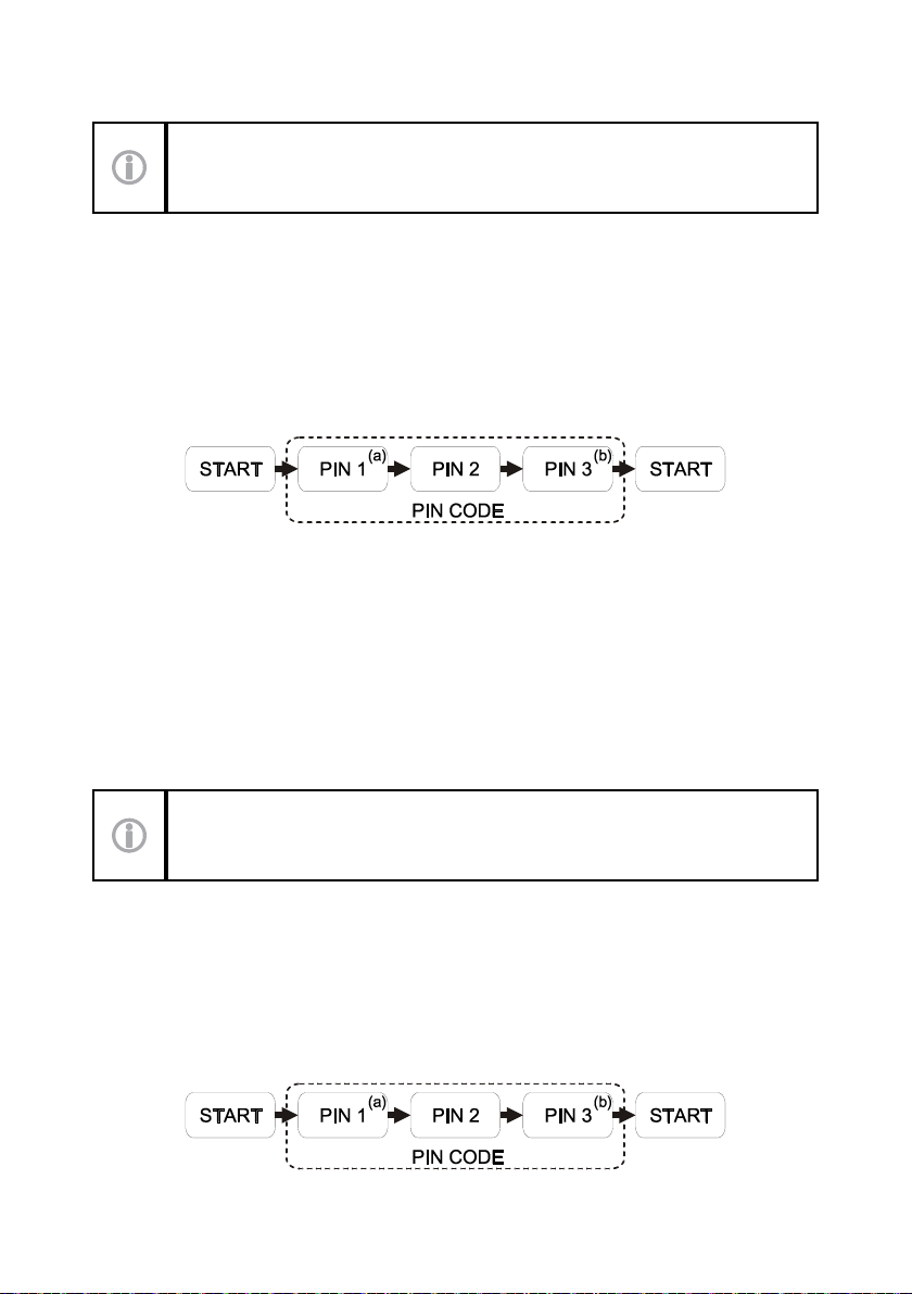
6.1.2 PIN CODE start up (no power keyswitch)
Considerthatthetransmittingunitwillswitcho3secondsafterlastactivation
of an actuator.
When the receiving unit is powered on, perform the following procedure:
1. press the START pushbutton until the green LED illuminates
2. activate the commands corresponding to PIN CODE in the correct sequence (PIN 1, PIN
2 and PIN 3 given in the technical data sheet).
a. PIN 1 shall not be included in the start up procedure if it coincides with the START
command.
b. PIN 3 shall not be included in the start up procedure if it coincides with the START
command.
3. press the START pushbutton until the green LED blinks slowly.
Note: default PIN CODE set by AUTEC is:
-PIN 1=START pushbutton
-PIN 2=FUNCTION pushbutton
-PIN 3=START pushbutton.
CustomPINCODEissetbyAutecuponrequestbythemachine'smanufacturerorbythose
who decided to install the radio remote control.
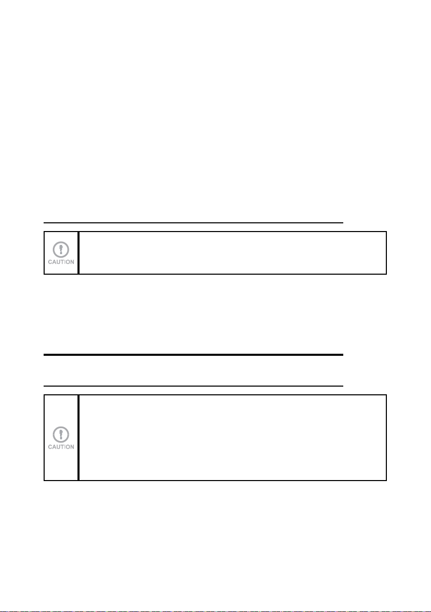
6.1.3 Power keyswitch and PIN CODE start up
When the receiving unit is powered on, perform the following procedure:
1. Insert a charged battery in the transmitting unit (see paragraph 7.1.1)
2. insert the power keyswitch in the transmitting unit (see paragraph 7.3.3).
Considerthatthetransmittingunitwillswitcho3secondsafterlastactivation
of an actuator.
3. press the START pushbutton until the green LED illuminates
4. activate the commands corresponding to PIN CODE in the correct sequence (PIN 1, PIN
2 and PIN 3 given in the technical data sheet).
a. PIN 1 shall not be included in the start up procedure if it coincides with the START
command.
b. PIN 3 shall not be included in the start up procedure if it coincides with the START
command.
5. press the START pushbutton until the green LED blinks slowly.

AUTEC - Air series
General operating instructions 9
LILK6E00-01
6.2 Command activation
When the radio remote control is started, it is possible to move the pushbuttons and switches
corresponding to the command you want to perform.
The user must be properly trained about the symbols on the transmitting unit panel, to be
aware of the matching between actuators and movements on the machine (symbols used are
denedbythemachinemanufactureraccordingtothefunctionsofthemachine).
6.3 Data Feedback Function
The user receives information and/or signals concerning the controlled machine by means
of the Data Feedback function.
Pay particular attention to LED indications during normal radio remote control operation: they
canbehelpfultoevaluatethemachine'sworkingstatus.
Any information signalled by LEDs for the Data Feedback function can never
be considered or used as a safety signal or for legal metrology.
When operating and moving the machine, remember that the radio remote
control does not intervene autonomously when potential hazardous
situations are signalled.
Specicmachineconditions(i.e.loadlimits,limitswitch,…)aresignalledthroughthe
illumination of the LEDs for the Data Feedback function .The signalled conditions depend
on the settings chosen by the machine manufacturer.
6.4 Radio link interruption
When the radio link is incorrect or interrupted, the receiving unit autonomously stops the
radio remote control.
The green LED on the transmitting unit switches from blinking slowly to fast blinking or
steady on.
Press the START pushbutton to start the radio remote control.
6.5 Transmitting unit automatic switch o
Thetransmittingunitautomaticallyswitchesowhen:
-thebatteryisat(seeparagraph6.5.1)
-the radio remote control is not used for a certain time (see paragraph 6.5.2)
Press the START pushbutton to start the radio remote control.
10
LILK6E00-01
Operation
AUTEC - Air series
6.5.1 Low battery
Thetransmittingunitindicatesifthebatteryisnotsucientlycharged(theredLEDblinksfast):
-the red LED blinks slowly (one blink per second): the battery has less than 1h run time.
-theredLEDblinksfast:thebatteryhasa10minuteruntimefromtherstsignal,after
whichthetransmittingunitautomaticallyswitcheso.
The battery needs to be replaced with a charged one (see paragraph 7.1).
6.5.2 When the transmitting unit is not used
If the transmitting units remains started with no enabled commands, it will automatically
switchoafterapredeterminedtimeframe.Thistimeframeisspeciedinthetechnicaldata
sheet (SWITCH-OFF).
Beforethetransmittingunitswitchesoautomatically,thegreenandredLEDsblinkalternating
for 30 seconds.
Activating any actuator corresponding to a movement command reduces the predetermined
automaticswitch-otime(SWITCH-OFF)tozero.
6.6 Switching o the transmitting unit
The transmitting unit shall be switched o each time work is stopped
Voluntarytransmittingunit'sswitchooccurs:
-when the power keyswitch (if present) is turned anti-clockwise
-when battery is removed (see paragraph 7.1.2)
-when the STOP pushbutton is pressed.
7 Operation
7.1 Battery
The Air series' transmitting units can only be powered by Autec rechargeable
batteries.
See the battery charger manual enclosed in the packaging with the battery
charger for any warnings and instructions regarding the batteries.
7.1.1 Battery insertion
Push the battery towards the contacts on the transmitting unit and insert it inside the housing.

AUTEC - Air series
Operation 11
LILK6E00-01
7.1.2 Battery removal
Push the battery towards the contacts on the transmitting unit and remove it from the housing.
7.1.3 Battery run time indicator
Perform the following procedure to check the run time of the battery in the transmitting unit:
1. switchothetransmittingunitandunlocktheSTOPpushbutton
2. activate command S1 (check in the technical data sheet which actuator it corresponds
to) and press the START pushbutton until LED 1, LED 2 and LED 3 (indicating battery
level) illuminate:
-1 LED on: low level
-2 LEDs on: medium level
-3 LEDs on: maximum level.
Run time indication disappears after some seconds.
7.2 ID internal tx memory
Thetransmittingunitmayrequirethe"IDinternaltxmemory",wheretheradioremotecontrol's
address is stored.The technical data sheet indicates if the "ID internal tx memory" is required.
7.3 Power keyswitch
The transmitting unit may have a power keyswitch. It can either be:
-mechanical key (see paragraph 7.3.1)
-Key ID 0-1 (see paragraph 7.3.2).
7.3.1 Mechanical key
The mechanical key makes it possible to power the transmitting unit. When the mechanical
key is required to be used in a transmitting unit, the radio remote control cannot work if it
is not inserted.
7.3.2 Key ID 0-1
The "Key ID 0-1" makes it possible to power the transmitting unit.
Itstorestheradioremotecontrol'saddress.Therefore,the"KeyID0-1"canonlybeused
in the transmitting unit belonging to its related radio remote control: when the transmitting
unit requires the "Key ID 0-1", the radio remote control cannot work if it is not inserted. The
technical data sheet indicates if the "Key ID 0-1" is required.
As the radio remote control address is stored in the "Key ID 0-1", use it with utmost care to
reduce risks that may result from incorrect handling.
7.3.3 power keyswitch insertion
Perform the following operations to insert the power keyswitch:
1. push the power keyswitch inside the corresponding housing
2. rotate the power keyswitch clockwise.
7.3.4 power keyswitch removal
Perform the following operations to remove the power keyswitch:
3. rotate the power keyswitch anticlockwise
4. pull the power keyswitch to remove it from the corresponding housing.

12
LILK6E00-01
Operation
AUTEC - Air series
7.3.5 BACK-UP UNIT
If the main transmitting unit cannot be used because it has been lost or damaged, it can be
replaced with a transmitting unit called "BACK-UP UNIT".
Itisidenticaltotheunitthatcannotbeusedanymore;theonlydierenceisthepresenceof
the plate “BACK-UP UNIT” on the battery housing.
Set DIP switch 2 in the "BACK-UP UNIT" as shown in the technical data sheet.
If the transmitting unit that can no more be used requires either a "Key ID
0-1" or an "ID internal tx memory" (see technical data sheet), move it to the
"BACK-UP UNIT" and perform the address saving procedure described below.
If the transmitting unit that can no more be used does not require either a
"Key ID 0-1" or an "ID internal tx memory" (see technical data sheet), perform
the PAIR procedure to pair the “BACK-UP UNIT” with a receiving unit (the
technical data sheet shows which PAIR procedure to use).
Address storage
With fully charged battery and power keyswitch in the "BACK-UP UNIT", perform this procedure:
1. press the START pushbutton until the green and red LEDs light up.
2. wait until the green LED blinks slowly
3. within 3 seconds, activate in sequence the commands corresponding to PIN 1, PIN 2 and
PIN 3 that compose the PIN code given in the technical data sheet.
IfthePINcodeisincorrect,theredLEDilluminatesandthetransmittingunitswitcheso.In
this case, the storage procedure shall be repeated.
If the PIN code is correct, the green LED turns steady on and the transmitting units switches
o:thisindicatesthattheaddresshasbeenstoredinthe"BACK-UPUNIT".Itisnow
possible to start the radio remote control and control the machine with the "BACK-UP UNIT"
transmitting unit.

AUTEC - Air series
Operation 13
LILK6E00-01
7.4 START pushbutton
The START pushbutton is used to:
-start the radio remote control (see paragraph 6.1)
-activate the horn when the radio remote control is started.
7.5 FUNCTION pushbutton
TheFUNCTIONpushbuttoncanbematchedwithdierentrelayfunctionsonthereceiving
unit (see technical data sheet).
7.6 STOP pushbutton
The STOP pushbutton should be pressed when it is necessary to immediately
stop the machine when a dangerous condition occurs.
When the STOP pushbutton is pressed, the machine stops and the transmitting unit switches
o.
To start working again after the STOP pushbutton has been pressed, do the following:
-make sure that the working and usage conditions are safe
-pull or turn the STOP pushbutton in the arrow direction to unlock it
-start up the radio remote control.

14
LILK6E00-01
Malfunction signalled by the transmitting unit
AUTEC - Air series
8 Malfunction signalled by the transmitting unit
Use the light signals on the transmitting unit to identify the radio remote control malfunction.
If the problem persists after the suggested solution has been carried out, contact the support
service of the machine manufacturer.
Signals Possible reason Solutions
The green LED is steady
on.
The transmitting and
receiving unit do not
communicate.
Start up the radio remote control. If the
radio remote control does not start up,
check that the receiving unit is powered
on.
The green LED blinks
fast.
Temporary loss of radio
link.
Bring the actuators corresponding
to movement commands to the
rest position and press the START
pushbutton until the green LED blinks
slowly.
The green LED blinks
slowly
(one blink per second).
The receiving unit may
not work correctly.
See "Receiving unit signals" in Part D of
the manual.
The red LED is steady
on during start up
The STOP pushbutton is
pressed or damaged.
Unlock the STOP pushbutton or contact
the support service.
The red LED blinks
twice per second during
start up.
At least one of the
commands that were
checked at start-up is
enabled or damaged (see
technical data sheet).
Bring the actuators corresponding to the
commands checked during start up to
the rest position or contact the support
service.
The red LED blinks
three times per second
during start up.
Thebatteryisat. Replace the battery with a charged one.
The red LED is steady
on for two seconds.
The transmitting unit does
not work correctly. Contact the support service.
The green and red LEDs
are steady on.
A wrong "Key ID 0-1" or
"ID internal tx memory"
has been inserted in the
transmitting unit.
Use the correct "Key ID 0-1" or "ID
internal tx memory".
You'reusinga"BACK-
UP UNIT" with the "Key
ID 0-1" or "ID internal
tx memory" of the
transmitting unit that has
been replaced.
Store the address in the "BACK-UP
UNIT" (see paragraph 7.3.5).

AUTEC - Air series
Malfunction signalled by the transmitting unit 15
LILK6E00-01
Signals Possible reason Solutions
The green and red LEDs
blink three times per
second during start up.
The “Key ID 0-1” is
damaged or the “ID
internal tx memory” is
damaged or not present.
Contact the support service.
The green LED blinks
and the red LED is
steady on during start
up.
The procedure
corresponding to the
UNPAIR submenu and
given in the document
"Menu of Transmitting
Unit (MTU)" has been
carried out.
Contact the support service.

This manual suits for next models
1
Table of contents
Other AUTEC Transmitter manuals


