manuals.online logo
Brands
  1. Home
  2. •
  3. Brands
  4. •
  5. Evikon
  6. •
  7. Transmitter
  8. •
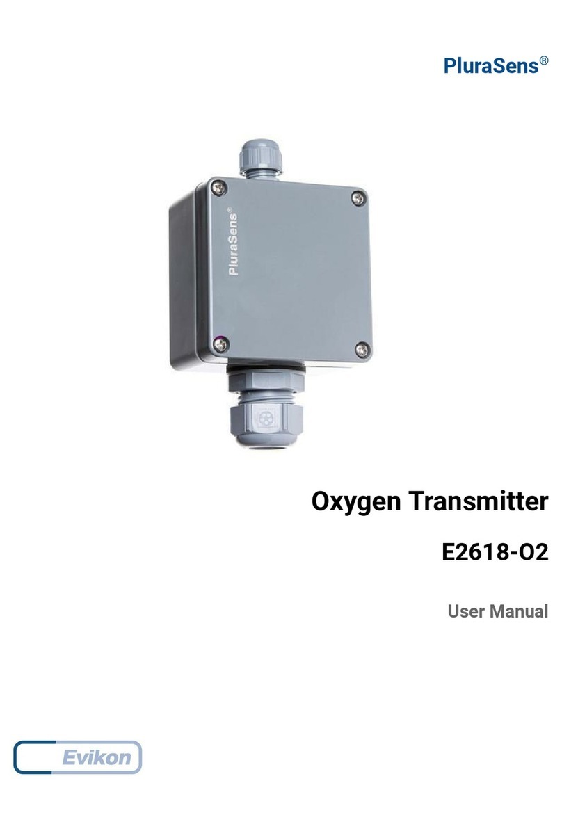
  9. Evikon PluraSens E2618-Cl2 User manual

Evikon PluraSens E2618-Cl2 User manual

Chlorine
Heavy greenish-yellow gas with a pungent, irritating odour. Highly toxic and
corrosive.
Chlorine is used in chemical industry and for bleaching and desinfection.
Chemical formula Cl2
Molar weight 70.9
Relative gas density (to air) 2.44
Conversion 1 ppm = 2.90 mg/m3
Boiling point -34.04 °C
Odour Pungent, irritating smell
Odour detection threshold Some individuals will not notice the
odour until it is more than three times
the exposure limit.
Hazards Nonflammable, but a strong oxidizer,
may react explosively with many
common chemicals.
Potent irritant of the eyes, mucous
membrane, skin and respiratory system.
Death can occur within minutes after
exposure of 400 to 1000 ppm. Chronic
exposure of 1 ppm can cause a
moderate, but permanent, reduction in
pulmonary function.
Exposure limits (Directive
2006/15/EC)
TWA not specified
STEL 1.5 mg/m3 /0.5 ppm
IDLH (NIOSH) 10 ppm
Conversion of ppm to mg/m3 is calculated for 25°C and 1 atm.
Installation guidelines
(See Installation and connections section for general information.)
Chlorine is considerably heavier than air and tends to sink. The sensor should be
placed at ca. 15 cm above the floor.
Calibration
E2618-Cl2 transmitters have been calibrated by Manufacturer with standard gas
mixtures before delivery. Provided that the sensor is used under moderate
conditions,the recommended interval for field recalibration is 6 months. Please
contact your dealer for more information.
Maintenance
Do not perform any maintenance operation with the power on.
Clean the device with soft damp cloth. Do not use any abrasive cleaning agents. Do
not immerse the device into water or any cleaning media.
Delivery set
–Transmitter E2618 (wall mount or duct mount version)
– Mounting accessories:
4 screws with plastic dowels for wall mount version
rubber flange for duct mount version.
fixing clamp for remote probe version
E2618-Cl2_UM_EN Rev 16.07.2019
Specifications
Sensor type electrochemical cell
Sampling method diffusion
Typical detection range 0...10 ppm
Maximum overload 100 ppm
Resolution / digital unit 0.1 ppm
Response time T90 <60s
Sensor lifetime > 2 years
Calibration interval 6 months
Signal update every 1 second
Load resistance RL < (Us - 2 V) / 22 mA for 4-20 mA
RL > 250 kOhm for 0-10 V mode
Digital interface RS485, Modbus RTU protocol
no galvanic isolation
Power supply options 11...30 VDC or 24 VAC
Power consumption < 2 VA
Analog outputs 2 × 4-20 mA / 0-10 V, user settable
Outputs assignment OUT1 2 gas; OUT2 2 gas
NOTE For LCD version only OUT1 is available.
Cable connections screwless spring loaded terminals
Enclosure grey ABS, wall or duct mount, protection class IP65
Dimensions H82 × W80 × D55 mm
CE marking according to 2014/30/EU and EN61326-1 requirements
Operating conditions
-20...+50 °C, 15...90 %RH, atmospheric pressure ±10%
non ATEXrated areas, non-aggressive atmosphere
NOTE The sensor may exhibit considerable sensitivity to
hydrogensulfide, nitrogen dioxidу and sulfur dioxide
LCD option
Operating temperature 0...+50 °C
Display dimensions 72 × 36 mm
Number of digits 3.5 7-segment
Character height 14 mm
Other features Backlight
Other options
Remote probe Protection IP65, default cable length 3.0 m;
max height 80 mm, max diameter 65 mm
Warranty
This product is warranted to be free from defects in material and workmanship for a
period of one year from the date of original sale. During this warranty period
Manufacturer will, at its option, either repair or replace product that proves to be
defective. This warranty is void if the product has been operated in conditions outside
ranges specified by Manufacturer or damaged by customer error or negligence or if
there has been an unauthorised modification.
Evikon MCI OÜ Teaduspargi 7, Tartu info@evikon.eu
Tel. +372 733 6310 50411 Estonia www.evikon.eu
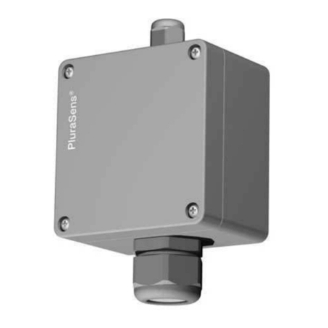
PluraSens®
Chlorine Transmitter
E2618-Cl2
User Manual
E2618-series transmitters belong to the PluraSens® family of multifunctional
measurement instruments. The instruments utilise gas sensors of various types with
excellent repeatability, stability and long lifetime
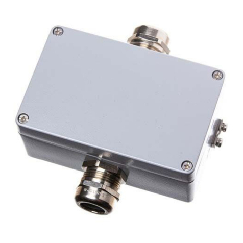
The devices are supplied either in duct-mount or wall-mount version. The wall mount
version of the device is available with remote probe. The remote probe is connected to
the main unit with shielded cable. Default connection cable length is 3 m.
E2618 series provides two independent analog outputs OUT1 and OUT2, user-
selectable to 4-20 mA or 0-10 V, proportional either to gas concentration or temperature.
RS485 Modbus RTU digital communication interface allows easy instrument
configuration and integration into various automation systems.
A design with LCD indicator is available as an option.
The version of your transmitter is marked on the package.
Safety requirements
Always adhere to the safety provisions applicable in the country of use.
Do not perform any maintenance operation with the power on. Do not let water or
foreign objects inside the device.
Operating conditions
The device should be used in explosion-safe (non ATEX -rated) indoor areas, without
aggressive gases in the atmosphere. See Specification table for more details.
Installation and connections
There are no precise rules or standards to follow when installing the gas detectors. The
following points must be taken into account:
application (air quality control or leakage detection),
properties of the space under investigation (room geometry, direction and velocity of
air flows etc),
detected gas (relative density to air, whether the gas is flammable, or toxiс, or oxygen
displacing),
safety: strong vibrations, mechanical shock, and the sources of strong
electromagnetic interference should be avoided,
the device should be accessible for maintenance and repair.
For early leakage detection install the sensor as close as possible to the potential
leakage sources (flanges, valves, pressure reducers, pumps, etc), taking into
consideration other points listed above. For general area monitoring without definite
leakage sources, the detectors should be distributed evenly in the room. For personal
safety control the detectors are installed in the breathing zone (at the height of the head
of people or animals). Recommended sensor position is vertical, pointing downwards.
See Installation guidelines section on the next page for more information.
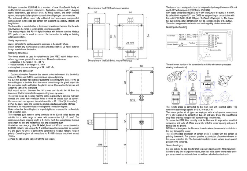
1. Wall mount version: Unscrew four lid screws and detach the lid from the transmitter.
Attach the device to a wall with screws passing through mounting holes (see
dimensional drawing below).
Duct mount version: Cut hole with a diameter of 36...45 mm in the air duct at the chosen
mounting place. Place the rubber flange aligning the holes in the flange and the air-duct
and fix the flange with four self-tapping screws. Pass the sensor probe through the
flange and adjust it to the appropriate depth. Unscrew four lid screws and detach the lid
from the transmitter.
2. Use two M16 cable glands to pass the cables of the power supply and of the external
devices. Attach the power cable to the device without turning it on. Using the
connection diagram below, connect the analog outputs and digital interface
terminals to the relevant devices according to your tasks.
The screwless quick connect spring terminals on the E2618 series devices are
suitable for a wide range of wires with cross-section 0,2...1,5 mm2. We recommend
to strip the wire end by 8...9 mm and tin it, or to use the wire end sleeves.
To connect the wire, insert the wire end into terminal hole. To disconnect, push the
spring loaded terminal lever, pull the wire out, and release the lever.
Use twisted pair cable, e.g. LiYY TP 2×2×0,5 mm2 or CAT 5, to connect the device
to RS485 network. Use one pair for A and B wires and the second pair for common
0 V and power +U wires to connect the transmitter to Fieldbus network. Respect
polarity. Overall length of all connections via RS485 interface should not exceed
1200 m. The type of each analog output can be independently changed between 4-
20 mA and 0-10 V with jumpers J1 (OUT1) and J2 (OUT2).
With closed jumper the output is 0-10 V, with open jumper the output is 4-20 mA.
By default both outputs OUT1 and OUT2 are assigned to gas concentration. The
device has built-in temperature sensor which may be tied to any of the outputs.
The output assignments and scales can be changed by Modbus commands.
We recommend to set the difference between the upper and bottom limits of the
output scale not narrower than 20% of detection range (for CO detectors the scales
down to 5% of range are allowed). In any case, do not set the output scale below
the tenfold resolution of the device.
NOTE If you use a version with LCD, only OUT1 is available.
3. Turn on the power. The sensor heating up may take up to five minutes after switching
on. During this period relays, analog outputs and Modbus interface are off. A LED
placed on the PCB of the device allows to control the connection process. The LED
response to different processes is presented in the table below.
Process LED mode
Sensor heating period Blinking 0.5 Hz (50% on, 50% off)
Sensor absence or malfunction Blinking 0.5 Hz (90% off, 10% on)
Modbus response The signal is modulated with short on-off pulses,
even single Modbus cycle is traceable*
Normal measurement Continuous light
4. Make sure that the transmitter is properly mounted, the external devices connected,
power on and control LED is constantly lit. Place the lid back and fix it with the screws.
The device is ready to use.
It is recommended to keep the device on constantly, except for periods of maintenance
and calibration, deplacement etc.
Sensor probe handling
The wall mount version of the transmitter is available with remote probe (see drawing
below for dimensions). The remote probe is connected to the main unit with shielded
cable. Default connection cable length is 3 m.The sensor probes of all types are
equipped with a hydrophobic microporous PTFE filter to protect the sensor from dust,
dirt and water drops. The filter may be replaced if it gets strongly contaminated. To
replace the PTFE filter, unscrew the M25 nut and remove the old filter. Place a new
filter into the nut and tighten it again.
NB! Never stab or press the filter near its centre where the sensor is located since this
may damage the sensor.
The recommended orientation of sensor probe is vertical with the sensor tip pointing
downwards. This prevents possible accumulation of condensed water on the sensor
protection filter. The horizontal orientation is also suitable. Avoid upward position of the
sensor tip.
Configuring
Gas transmitters E2618 share all functionalities of the PluraSens® multifunctional
transmitter platform. The features and options include:
- digital output change rate limiting filter
- digital integrating (averaging) filter
- temperature measurement channel with internal sensor
- free assignment of each analog output to chosen parameter
- flexible setting of analog output scales for each output
- output shift and slope adjustment for calibration
- Modbus controlled forced state option for analog outputs .
E2618 can be configured through its RS485 interface by Modbus RTU commands. A
standard configuration kit includes Model E1087 USB-EIA485 converter and a software
pack. Please contact your Seller or the Manufacturer for more information.
Return to default settings
To reset the device’s Slave ID, baudrate and sbit number to factory settings, proceed as
follows:
1. De-energize the device
2. Connect the J3 jumper
3. Turn on the device
4. De-energize the device
5. Disconnect the J3 jumper
6. Turn on the device
RS485 communication interface
See Annex 1
36
77
Ø35...36 Ø50
120°
Ø 65 80
32 7
Ø34 max
Hole
35
OUT1
OUT2
0V
A
B
+U
J3
J1 J2
Fieldbus
Controller
Supply
Power
Control LED
Input 1 4-20 mA / 0-10 V
Input 4-20 mA / 0-10 V2
0V / GND
0V
+24V
J1: OUT1 type (open: 4-20 mA; closed: 0-10 V)
J : OUT type2 2 (open: 4-20 mA; closed: 0-10 V)
J : 3 return to factory settings
SENSOR
55 80
130
82
Ø4 mm
M25
M16
50
70
200
M16
80
Ø35
2 03
M25
35
82
55
E2618_UM_EN Annex 1. Modbus RTU Communication Reference
RS 85 communication interface
Databits: 8
Parity: none
Stop bits: 1 or 2
Protocol: Modbus RTU
Supported Modbus functions:
03 - read ultiple registers
06 - write single register
Communication parameters
Parameter Permitted values Default
Supported
baudrates
1200, 2400, 4800, 9600, 19200,
38400, 57600
9600
Data bits 8 8
Parity none none
Stop bits 1, 2 1
Protocol Modbus RTU
Modbus functions 03 - read ultiple registers
06 - write single register
Error codes 01 - illegal function
02 - illegal data address
03 - illegal data value
04 - slave device failure (details of last error 04
can be read fro register 0x0008)
Modbus holding registers
Register addresses are shown 0-based, Addr in hexadeci al, Reg in deci al for at.
Modbus holding register nu bers MHR are shown in deci al 1-based for at, and ay be addressed either fro 00001 or 40001 base.
Addr
Reg / MHR
RW
Description
Supported values (dec)
Default
0x0001
1
R
Hardware version
-
0x0002
2
R
Software version
-
0x0003
3
R
Product serial nu ber
1...65535
-
0x0004
4
RW
Slave ID (net address) *
1...247 **
1
0x0005
5
RW
Baudrate *
1200, 2400, 4800, 9600, 19200, 38400, 57600
9600
0x0006
6 /40007
RW
Response delay, s
1...255
10
0x0007
7 / 40008
RW
Stop bits *
1: no parity bit, 1 stop bit (default after factory reset)
2: no parity bit, 2 stop bits
3: odd parity, 1 stop bit
4: even parity, 1 stop bit
NOTE
: 3 and 4 are available starting fro the Sofrware version 0x218 (dec. 536)
1
0x0008
8 /40009
R
Last error code
1...255
-
0x0011
17 / 40018
RW
Restarts counter
write ‘42330’ to restart device (no response will follow)
-
0x0097
151 /40152
R
Sensor type code
0...65535
0
0x0098
152 /40153
R
Output units code
0 - pp , 1 - ‰, 2 - %
0
* - The new value is applied after restart.
** - Broadcast slave ID 0 can be used to assign a new ID to device with unknown ID. When addressing by ID 0 the device shall be the only Modbus instru ent in the network. The device will not respond to Master co and when addressed by ID 0.
*** - This value is dyna ic and not kept in EEPROM after restart
E2618_UM_EN Annex 1. E2618 series Modbus holding registers (part 2)
Register addresses are shown 0-based, Addr in hexadeci al, Reg in deci al for at.
Modbus holding register nu bers MHR are shown in deci al 1-based for at, and ay be addressed either fro 00001 or 40001 base.
Addr
Reg / MHR
RW
Description
Supported values (dec)
Default
0x00A2 162 / 40163 RW
Zero adjust ent for te perature data, °C ×
100 -32000...+32000 (-320,00...+320,00 °C) 0
0x00A5 165 / 40166 RW Zero adjust ent for gas data, ADC -32000...+32000 ADC units 0
0x00A6
166 / 40167
RW
Slope adjust ent for gas data
1...65535
512
0x00A7
167 / 40168
RW
Change rate li it for gas data,
pp (‰ for O
2
) / s
1...32000, 0 - no li it
0
0x00A8 168 / 40169 RW Integrating filter ti e constant, s 1...32000 (seconds), 0 - no filter 0
0x00C9
201 / 40202
RW
Para eter tied to analog output 1
0-none
1- te perature
2- gas concentration
9- forced Modbus control, value set in MHR / 40204
2
0x00CA
202 / 40203
RW
Para eter tied to analog output 2
0-none
1- te perature
2- gas concentration
9- forced Modbus control, value set in MHR / 40205
2
0x00CB
203 / 40204
RW
Forced value for analog output 1***
0...1000 (0,0%...100,0% of output scale)
0
0x00CC
204 / 40205
RW
Forced value for analog output 2***
0...1000 (0,0%...100,0% of output scale)
0
0x00FF 255 / 40256 RW
Sensor, analog outputs, LED
and buzzer status
bit[0]=0/1 - sensor present/absent, read-only!
bit[1]=0/1 - analog outputs deactivated/activated,
bit[2]= 0/1 - in case the sensor is absent, turn signaling off/on analog output1,
bit[3]=0/1 - in case the sensor is absent, turn on signaling with low current/high current
on analog output1; if bit[2]==0 this bit will be ignored,
bit[4]=0/1 - in case of sensor absent, turn signaling off/on analog output2
bit[5]=0/1 - in case of sensor absent, turn on signaling with low current/high current on
analog output2; if bit[4]==0 this bit will be ignored,
bit[6]=0/1 - current/voltage output detected on output1, read-only!
bit[7]=0/1 - current/voltage output detected on output2, read-only!
bit[8]=0/1 - LED deactivated/activated (always 0 for E2618),
bit[9]=0/1 - buzzer deactivated/activated (always 0 for E2618) -
0x0100
256 / 40257
R
Raw te perature data, °C×100
signed integer, -4000...+8500 (-40,00...+85,00 °C)
0x0101
257 / 40258
R
Raw gas sensor data
ADC data 0...4095
0x0102
258 / 40259
R
Measured te perature, °C×100
signed integer, -4000...+12500 (-40,00...+125,00 °C)
0x0103
259 / 40260
R
Gas concentration, pp / ‰
signed integer, -32000...+32000 (pp / ‰)
0x0105
261 / 40262
RW
0% value for analog output 1
signed integer, -32000...+32000 (pp / ‰)
0
0x0106
262 / 40263
RW
100% value for analog output 1
signed integer, -32000...+32000 (pp / ‰)
1000
0x0107
263 / 40264
RW
0% value for analog output 2
signed integer, -32000...+32000 (pp / ‰)
0
0x0108
264 / 40265
RW
100% value for analog output 2
signed integer, -32000...+32000 (pp / ‰)
1000
* - The new value is applied after restart.
** - Broadcast slave ID 0 can be used to assign a new ID to device with unknown ID. When addressing by ID 0 the device shall be the
only Modbus instru ent in the network. The device will not respond to Master co and when addressed by ID 0.
*** - This value is dyna ic and not kept in EEPROM after restart

Other Evikon Transmitter manuals

Evikon PluraSens E2638 Series User manual

Evikon

Evikon PluraSens E2638 Series User manual

Evikon PluraSens E2658 Series User manual

Evikon

Evikon PluraSens E2658 Series User manual

Evikon PluraSens E2618 Series User manual

Evikon

Evikon PluraSens E2618 Series User manual

Evikon E2618-NH3 User manual

Evikon

Evikon E2618-NH3 User manual

Evikon PluraSens E2638-SO2 User manual

Evikon

Evikon PluraSens E2638-SO2 User manual

Evikon PluraSens E2658-O3 User manual

Evikon

Evikon PluraSens E2658-O3 User manual

Evikon PluraSens E2418DF User manual

Evikon

Evikon PluraSens E2418DF User manual

Evikon PluraSens E2638-O3 User manual

Evikon

Evikon PluraSens E2638-O3 User manual

Evikon PluraSens E2658-NH3-E User manual

Evikon

Evikon PluraSens E2658-NH3-E User manual

Evikon E2638-H2S User manual

Evikon

Evikon E2638-H2S User manual

Evikon PluraSens E2648-VOC User manual

Evikon

Evikon PluraSens E2648-VOC User manual

Evikon PluraSens E2618-LEL User manual

Evikon

Evikon PluraSens E2618-LEL User manual

Evikon PluraSens E2618-O3 User manual

Evikon

Evikon PluraSens E2618-O3 User manual

Evikon PluraSens E2608-PID User manual

Evikon

Evikon PluraSens E2608-PID User manual

Evikon PluraSens E2658-PID User manual

Evikon

Evikon PluraSens E2658-PID User manual

Evikon PluraSens E2618-O2 User manual

Evikon

Evikon PluraSens E2618-O2 User manual

Evikon PluraSens E2670-PID User manual

Evikon

Evikon PluraSens E2670-PID User manual

Evikon PluraSens E2648-H2S User manual

Evikon

Evikon PluraSens E2648-H2S User manual

Evikon PluraSens E2648-C2H4 User manual

Evikon

Evikon PluraSens E2648-C2H4 User manual

Evikon PluraSens E2418DP User manual

Evikon

Evikon PluraSens E2418DP User manual

Evikon PluraSens E2227 User manual

Evikon

Evikon PluraSens E2227 User manual

Evikon E2608-CO2-50K User manual

Evikon

Evikon E2608-CO2-50K User manual

Evikon PluraSens E2618-C2H4 User manual

Evikon

Evikon PluraSens E2618-C2H4 User manual

Evikon PluraSens E2618 Series User manual

Evikon

Evikon PluraSens E2618 Series User manual

Popular Transmitter manuals by other brands

ATX QFOT1310 Series user manual

ATX

ATX QFOT1310 Series user manual

Monacor JTS T-850B/1 instruction manual

Monacor

Monacor JTS T-850B/1 instruction manual

Sentrol 4003 manual

Sentrol

Sentrol 4003 manual

MuxLab 500058-WP-UK Quick installation guide

MuxLab

MuxLab 500058-WP-UK Quick installation guide

E-Image MT-800 user guide

E-Image

E-Image MT-800 user guide

BWI Eagle AIR-EAGLE SR PLUS 36-1400-4B-DC Product information bulletin

BWI Eagle

BWI Eagle AIR-EAGLE SR PLUS 36-1400-4B-DC Product information bulletin

Crestron HD-TX-4KZ-111-1G Getting started

Crestron

Crestron HD-TX-4KZ-111-1G Getting started

ARG ARG-TX72BP Manual and user guide

ARG

ARG ARG-TX72BP Manual and user guide

Vaisala HUMICAP MMT310 user guide

Vaisala

Vaisala HUMICAP MMT310 user guide

JCM Technologies KEEpush quick guide

JCM Technologies

JCM Technologies KEEpush quick guide

GESTRA TRV 5-40 installation instructions

GESTRA

GESTRA TRV 5-40 installation instructions

MG BCT instruction manual

MG

MG BCT instruction manual

EnOcean PTM 535Z user manual

EnOcean

EnOcean PTM 535Z user manual

Vega VEGADIF 85 operating instructions

Vega

Vega VEGADIF 85 operating instructions

Omega Engineering CYTX231 Series user guide

Omega Engineering

Omega Engineering CYTX231 Series user guide

M-system M5XCRS instruction manual

M-system

M-system M5XCRS instruction manual

Williams AV PPA T27 user manual

Williams AV

Williams AV PPA T27 user manual

Endress+Hauser TMD1000 operating instructions

Endress+Hauser

Endress+Hauser TMD1000 operating instructions

manuals.online logo
manuals.online logoBrands
  • About & Mission
  • Contact us
  • Privacy Policy
  • Terms and Conditions

Copyright 2025 Manuals.Online. All Rights Reserved.