Air Quality Engineering MistBuster 500 User manual

MistBuster®500, 850C, 850 and 2000
CE Complient Versions
Installation and Operation Manual
Protected by U.S. Patent Numbers 6,428,611 and 7,717,984
Machine Mountable Mist & Smoke Collector
The MistBuster®series of air cleaners are designed for the ltration of mist and smoke
generated from metal machining applications. This appliance is intended to be used in
commercial areas.
Air Quality Engineering, founded in 1973, is proud to offer a continued, superior
level of experience in manufacturing complete air filtration systems that provide
the highest performance, efficiency, and capacity for the money. Our sales and
engineering team’s mission is to identify the most cost-effective, high-quality
solutions for our customers’ needs, whether commercial, industrial or residential.
Supplying Clean Air to Industry

Air Quality Engineering Inc., has a policy of continuing product improvement and reserves the right to make changes in design and specification without notice.
PAGE
2
MistBuster®
7140 Northland Drive North, Minneapolis, MN 55428, USA
PHONE: 763-531-9823 • FAX: 763-531-9900 • TOLL FREE: 1-800-328-0787
EMAIL: info@air-quality-eng.com • www.air-quality-eng.com
TABLE OF CONTENTS
PAGE
MB500, MB850C AND MB850 SPECIFICATIONS ..................................................... 3
MB2000 SPECIFICATIONS ...................................................................... 4
ELECTRICAL ................................................................................. 5
START UP ................................................................................... 9
ROUTINE MAINTENANCE ....................................................................... 9
HEPA FILTER OPTION INSTALLATION ............................................................. 10
CELL PARTS ................................................................................ 10
WARRANTY ................................................................................. 11
DECLARATION OF CONFORMITY ................................................................ 12
INSTALLATION
https://www.air-quality-eng.com/installation-mistbusters/
PARTS LIST
https://www.air-quality-eng.com/parts-mistbusters/
TROUBLESHOOTING
https://www.air-quality-eng.com/troubleshooting-mistbusters/

Air Quality Engineering Inc., has a policy of continuing product improvement and reserves the right to make changes in design and specification without notice.
PAGE
3
MistBuster®
7140 Northland Drive North, Minneapolis, MN 55428, USA
PHONE: 763-531-9823 • FAX: 763-531-9900 • TOLL FREE: 1-800-328-0787
EMAIL: info@air-quality-eng.com • www.air-quality-eng.com
MB500, MB850C & MB850 Specifications
3
MB500 and MB850 SPECIFICATIONS
-IMPORTANT -
THE SPECIFICATIONS GIVEN IN THIS PUBLICATION DO NOT INCLUDE NORMAL MANUFACTURING TOLERANCES.
THEREFORE, THIS UNIT MAY NOT MATCH THE LISTED SPECIFICATIONS EXACTLY. ALSO, THIS PRODUCT IS
TESTED AND CALIBRATED UNDER CLOSELY CONTROLLED CONDITIONS AND SOME MINOR DIFFERENCES IN
PERFORMANCE CAN BE EXPECTED IF THOSE CONDITIONS ARE CHANGED.
DIMENSIONS MB500: Cabinet – 27.13”L [690mm]x15” W [381mm]x17.70”H [443mm] See Fig.1
DIMENSIONS MB850C:
DIMENSIONS MB850:
INLET OPENING:
WEIGHT MB500:
WEIGHT MB850C:
WEIGHT MB850:
CABINET:
AIRFLOW MB500:
AIRFLOW MB850C:
AIRFLOW MB850:
EFFICIENCY:
FILTRATION:
Cabinet – 27.13”L [690mm]x15” W [381mm]x22.90” H [582mm] See Fig.1
Cabinet – 27.13”L [690mm]x15” W [381mm]x28.01” H [711mm] See Fig.1
16.62” [422mm] x 9.08” [231mm]. See Fig. 3
65 lbs [30kg] installed weight; 76 lbs [35kg] shipping weight.
93 lbs [42kg] installed weight; 105 lbs [48kg] shipping weight.
99 lbs [45kg] installed weight; 111 lbs [50kg] shipping weight.
16 gauge steel cabinet with chemical resistant baked enamel, textured finish
500cfm [850cmh] @ 0.6”wg” [149Pa] top discharge
850cfm [1444cmh] @ 0.7”wg [174Pa] top discharge
Up to 99.9% efficiency on submicron particles per ASHRAE 52.2 standard
1st Stage - 4" aluminum mesh impinger
2nd Stage -AQE Advantage™ (Long Life) Electronic Cell
MB 850C & MB850 ONLY 3rd Stage -MistBuster (High Efficiency)Cell
MB 850 ONLY OPTIONAL 4Th Stage – MistBuster (High Efficiency) Cell
OPTIONAL Final Stage -HEPA filter 99.97% efficiency or ESF Filter; or Carbon Module
POWER SUPPLY: Self-regulating, dual voltage, solid-state power supply; two for MB850
MOTORIZED IMPELLER:
POWER:
POWER CORD:
IP RATING:
Backward curved, vibration-free, direct drive rated at 710cfm@0”wg for
MB500 and at 980cfm@0”wg for MB850C & MB850
~115 VAC, 60 HZ, 2.5 Amps OR 230 VAC, 60 Hz, 1.25 Amp for MB500
~115 VAC, 60 HZ, 3.9 Amps OR 230 VAC, 60 Hz, 1.95 Amp for MB850C
~115 VAC, 60 HZ, 4.3 Amps OR 230 VAC, 60 Hz, 2.15 Amp for MB850
MistBuster Units are NOT Dual Voltage
Ten-foot power cord with standard molded plug
Ingress Protection according to IEC 60529 - IP 20
MANUFACTURE DATE: Refer to first 4 digits of serial number (e.g. 1528 indicates week 28 of 2015)
SOUND PRESSURE 73.9 ± 2.5 dB(A), measured 1m from the cabinet door at maximum speed
LEVEL: during normal operation (Model 850).
Figure 1
27.10
Front View Side View
17.70
15.00
14.00
27.10
Front View Side View
22.90
14.00
15.00
Front View Side View
15.00
14.00
27.10
28.01
Figure 1
MB500 MB850C MB850

Air Quality Engineering Inc., has a policy of continuing product improvement and reserves the right to make changes in design and specification without notice.
PAGE
4
MistBuster®
7140 Northland Drive North, Minneapolis, MN 55428, USA
PHONE: 763-531-9823 • FAX: 763-531-9900 • TOLL FREE: 1-800-328-0787
EMAIL: info@air-quality-eng.com • www.air-quality-eng.com
MB2000 Specifications
4
MB2000 SPECIFICATIONS
-IMPORTANT -
THE SPECIFICATIONS GIVEN IN THIS PUBLICATION DO NOT INCLUDE NORMAL MANUFACTURING TOLERANCES.
THEREFORE, THIS UNIT MAY NOT MATCH THE LISTED SPECIFICATIONS EXACTLY. ALSO, THIS PRODUCT IS
TESTED AND CALIBRATED UNDER CLOSELY CONTROLLED CONDITIONS AND SOME MINOR DIFFERENCES IN
PERFORMANCE CAN BE EXPECTED IF THOSE CONDITIONS ARE CHANGED.
DIMENSIONS: Cabinet – 26”W x 27.56”D x 27.50”H. See Fig. 2.
INLET OPENING: 20.75” x 16”. See Fig. 3.
WEIGHT: 203 lbs. installed weight; 230 lbs. shipping weight.
CABINET: 16 gauge steel cabinet with a chemical
resistant baked enamel, textured finish.
AIRFLOW: 50-1650cfm @ 0.7”wg top discharge
EFFICIENCY: Up to 99.9% efficiency on submicron particles per ASHRAE 52.2 standard test.
FILTRATION: 1st Stage -4" aluminum mesh impinger
2nd Stage -AQE Advantage™ (Long Life) Electronic Cell
3rd Stage -MistBuster (High Efficiency) Cell
OPTIONAL 4Th Stage – MistBuster (High Efficiency) Cell
OPTIONAL 5Th Stage -HEPA filter 99.97% efficiency; ESF Filter; or
Carbon Module
POWER SUPPLIES: Two (optional third), independent, self-regulating, dual voltage, solid-state
power supplies
Two backward curved, vibration-free, direct drive rated at 980cfm @ 0”wgMOTORIZED IMPELLER:
POWER:
POWER CORD:
IP RATING:
~115 Vac, 60 Hz, 8.2Amp
~230 Vac, 60 Hz, 4.1 Amp
Ten-foot power cord with standard molded plug
Ingress Protection according to IEC 60529 - IP 20
MANUFACTURE DATE: Refer to first 4 digits of serial number (e.g. 1528 indicates week 28 of 2015)
SOUND PRESSURE 73.9 ± 2.5 dB(A), measured 1m from the cabinet door at maximum speed
LEVEL: during normal operation (Model 2000).
Figure 2
26.0 27.56
27.5
26.56
Front View Side View
Figure 2

Air Quality Engineering Inc., has a policy of continuing product improvement and reserves the right to make changes in design and specification without notice.
PAGE
5
MistBuster®
7140 Northland Drive North, Minneapolis, MN 55428, USA
PHONE: 763-531-9823 • FAX: 763-531-9900 • TOLL FREE: 1-800-328-0787
EMAIL: info@air-quality-eng.com • www.air-quality-eng.com
Electrical Installation
10
WARNING
All electrical work must be done by a qualified
electrician and with accordance to local codes and
regulations.
Be certain that the power source is compatible
with the model ordered. See the rated voltage on
the inside of the filter access door.
Proper grounding of the MistBuster is essential for
safety and operation.
Cord Connected
The MistBuster is equipped with a 10-foot
[3048mm] power cord with a standard molded
(15 amp rated) plug. There must be a standard
grounded outlet provided within 10 feet
[3048mm] of the MistBuster. Route the power
cord so that it is out of the way of the building’s
occupants and so that it does not interfere with
the machine operation.
Conduit Connected
The MistBuster can be hard wired. All wiring
must comply with applicable codes and
ordinances. All work must be done by a
qualified electrician.
The wiring compartment is on the left side of the
MistBuster. Removing the side cover accesses
it.
Remote Mounted Controller Option
The MistBuster can be ordered with the variable
speed controller shipped separately. In place of
the switch on the MistBuster, there is a
2”[51mm] x 4”[102mm] electrical box and cover.
Install a field supplied electrical box in the
desired location and run three 14-gauge wires
from the remote mounted electrical box to the
MistBuster.
NOTE: When the MistBuster is ordered with
a remote option, it will run on high speed
only until the remote switch wiring is
complete.
ELECTRICAL INSTALLATION
MistBuster 500 CE
R

Air Quality Engineering Inc., has a policy of continuing product improvement and reserves the right to make changes in design and specification without notice.
Supplying Clean Air to Industry
PAGE
6
MistBuster®
7140 Northland Drive North, Minneapolis, MN 55428, USA
PHONE: 763-531-9823 • FAX: 763-531-9900 • TOLL FREE: 1-800-328-0787
EMAIL: info@air-quality-eng.com • www.air-quality-eng.com
MistBuster 850 CE
R

Air Quality Engineering Inc., has a policy of continuing product improvement and reserves the right to make changes in design and specification without notice.
PAGE
7
MistBuster®
7140 Northland Drive North, Minneapolis, MN 55428, USA
PHONE: 763-531-9823 • FAX: 763-531-9900 • TOLL FREE: 1-800-328-0787
EMAIL: info@air-quality-eng.com • www.air-quality-eng.com
Electrical Installation
MistBuster 850C CE
R

Air Quality Engineering Inc., has a policy of continuing product improvement and reserves the right to make changes in design and specification without notice.
PAGE
8
MistBuster®
7140 Northland Drive North, Minneapolis, MN 55428, USA
PHONE: 763-531-9823 • FAX: 763-531-9900 • TOLL FREE: 1-800-328-0787
EMAIL: info@air-quality-eng.com • www.air-quality-eng.com
Electrical Installation
MistBuster
R
2000 CE

Air Quality Engineering Inc., has a policy of continuing product improvement and reserves the right to make changes in design and specification without notice.
PAGE
9
MistBuster®
7140 Northland Drive North, Minneapolis, MN 55428, USA
PHONE: 763-531-9823 • FAX: 763-531-9900 • TOLL FREE: 1-800-328-0787
EMAIL: info@air-quality-eng.com • www.air-quality-eng.com
Start Up
Routine Maintenance
13
1. Start up the MistBuster by rotating the control
knob clockwise. Set the airflow at the
minimum airflow setting that will maintain
the proper negative pressure. In most cases,
the three o’clock setting on the speed
controller will provide enough airflow to
maintain negative pressure. This will reduce
noise and maintenance, and will increase
efficiency.
2. The performance indicator light should be on
when the blower is running.
3. Push the test button to momentarily short out the
collector on the electronic cells. Arcing indicates
that the cells are energized properly.
4. The toggle switch on the front of the
MistBuster is used to compensate for nuisance
arcing that occurs with some water soluble or
synthetics. Switch to oil mode to run onthe
highest voltage, if nuisance arcing occurs, switch
the toggle switch to water mode.
The direct mount MistBuster captures mist
droplets from machine tools using either petroleum
or synthetic machining fluids. The collected fluids
drain directly back into the machine tool through
the inlet opening. This draining process actually
helps to keep the impingers and electronic cell
clean.
The mist impingers and electronic cell will need to
be cleaned periodically. The exact maintenance
interval is determined by each specific application.
Water soluble and synthetic machining fluids will
require more frequent cleaning than will petroleum
machining fluids. During the first few months of
operation, inspect the impingers and electronic
cell. When you have an excessive buildup on the
mist impingers and electronic cell, they will need to
be cleaned.
Parts Washer Method
The mist impingers and electronic cell can be
cleaned with a parts washer. Make sure that the
cleaning fluid used is aluminum safe and the
maximum pressure does not exceed 60 psi
[414kPa].
Manual Cleaning the Mist Impingers
Soak impingers in a solution of hot water and
alkaline detergent for 10-15 minutes. Thoroughly
rinse with hot water to remove any residual
detergent.
Manual Cleaning the Electronic Cell
1. Fill the wash tub with cell cleaning detergent
and hot water per the detergent
manufacturer’s instructions.
2. Immerse the cell in cleaner solution for five
minutes.
3. Thoroughly rinse the cell with very hot water.
Make certain no residue remains on the cell.
4. Inspect the collector plates for cleanliness.
Repeat wash procedure, if necessary. Check
for broken wires and bent collector plates.
The cell can be installed back into the
MistBuster. The indicator light may remain off
for the normal two hour drying time.
NOTE: If water-soluble machining fluids are
used, it would be best to coat the cell with AQE
Cell Coat after washing the cell. See the Parts
List section for the part numbers for the
detergent and cell coat.
STARTUP
ROUTINE MAINTENANCE
CAUTION
1. Be extremely careful when working with
the electronic cell. The edges of the
collector plates and the ionizing wires on
the cell may be sharp.
2. When cleaning the cell, be sure to wear
appropriate protective gear, especially
goggles and gloves. Skin contact with
alkaline detergent solution should be
avoided. See warning label on the
detergent.
3. The electronic cell must be handled with
care to avoid damage.
13
1. Start up the MistBuster by rotating the control
knob clockwise. Set the airflow at the
minimum airflow setting that will maintain
the proper negative pressure. In most cases,
the three o’clock setting on the speed
controller will provide enough airflow to
maintain negative pressure. This will reduce
noise and maintenance, and will increase
efficiency.
2. The performance indicator light should be on
when the blower is running.
3. Push the test button to momentarily short out the
collector on the electronic cells. Arcing indicates
that the cells are energized properly.
4. The push/pull knob on the back of the
MistBuster is used to compensate for nuisance
arcing that occurs with some water soluble or
synthetics. Pull the knob out for the highest
voltage, if nuisance arcing occurs, push the
knob in.
The direct mount MistBuster captures mist
droplets from machine tools using either petroleum
or synthetic machining fluids. The collected fluids
drain directly back into the machine tool through
the inlet opening. This draining process actually
helps to keep the impingers and electronic cell
clean.
The mist impingers and electronic cell will need to
be cleaned periodically. The exact maintenance
interval is determined by each specific application.
Water soluble and synthetic machining fluids will
require more frequent cleaning than will petroleum
machining fluids. During the first few months of
operation, inspect the impingers and electronic
cell. When you have an excessive buildup on the
mist impingers and electronic cell, they will need to
be cleaned.
Parts Washer Method
The mist impingers and electronic cell can be
cleaned with a parts washer. Make sure that the
cleaning fluid used is aluminum safe and the
maximum pressure does not exceed 60 psi
[414kPa].
Manual Cleaning the Mist Impingers
Soak impingers in a solution of hot water and
alkaline detergent for 10-15 minutes. Thoroughly
rinse with hot water to remove any residual
detergent.
Manual Cleaning the Electronic Cell
1. Fill the wash tub with cell cleaning detergent
and hot water per the detergent
manufacturer’s instructions.
2. Immerse the cell in cleaner solution for five
minutes.
3. Thoroughly rinse the cell with very hot water.
Make certain no residue remains on the cell.
4. Inspect the collector plates for cleanliness.
Repeat wash procedure, if necessary. Check
for broken wires and bent collector plates.
The cell can be installed back into the
MistBuster. The indicator light may remain off
for the normal two hour drying time.
NOTE: If water-soluble machining fluids are
used, it would be best to coat the cell with AQE
Cell Coat after washing the cell. See the Parts
List section for the part numbers for the
detergent and cell coat.
STARTUP
ROUTINE MAINTENANCE
CAUTION
1. Be extremely careful when working with
the electronic cell. The edges of the
collector plates and the ionizing wires on
the cell may be sharp.
2. When cleaning the cell, be sure to wear
appropriate protective gear, especially
goggles and gloves. Skin contact with
alkaline detergent solution should be
avoided. See warning label on the
detergent.
3. The electronic cell must be handled with
care to avoid damage.

Air Quality Engineering Inc., has a policy of continuing product improvement and reserves the right to make changes in design and specification without notice.
PAGE
10
MistBuster®
7140 Northland Drive North, Minneapolis, MN 55428, USA
PHONE: 763-531-9823 • FAX: 763-531-9900 • TOLL FREE: 1-800-328-0787
EMAIL: info@air-quality-eng.com • www.air-quality-eng.com
Hepa Filter Option
14
HEPA FILTER OPTION
NOTICE
1. Handle the HEPA filter carefully to avoid
damage to the filter media.
2. The HEPA filter weighs 25 lbs for MB500
and MB850; 40 lbs for MB2000 clean and
adds an additional 12” [305mm] to the
height of the MistBuster.
1. Install the two anchor brackets to the center
of both sides of the MistBuster cabinet.
Remove the two bolts/washers (on each
side of the MistBuster) and position the
anchor bracket and bolt into place using the
same bolts /washers.
2. Center the HEPA filter on top of the
MistBuster exhaust grille with gasket side
down. (NOTE: Airflow arrow points up
towards ceiling).
FIGURE 9
Install the HEPA retainer brackets by hooking
one end to the filter frame and bolting the
21
CELL PARTS
Figure 10
MistBuster Troubleshooting
NOTE: The blower and motor in the MistBuster are integrated. The unit will not function unless
the door interlock switch is depressed (i.e. the filter access door is closed.)
INDICATOR LIGHT IS ON AND MOTOR DOES NOT RUN
1. Inspect the motor by checking to see if the motor spins freely by hand. If the motor does not
spin freely by hand check for obstructions or replace motor as necessary.
2. If the motor spins freely by hand try spinning the motor clockwise or counterclockwise then with
the motor spinning turn the unit on. If the motor runs and the fan speed can be adjusted by the
speed controller replace the motor capacitor.
3. Try bypassing the speed controller by hooking the supply voltage going into the speed controller
directly to the wire that goes from the speed controller to the motor (see schematic). If the
motor works with the speed controller bypassed replace the speed controller.
Air
Flow
End
Plate
Comb
Collector
Fins
Ionizing
Insulator
Collector
Contact
Ionizer
Contact
Ionizer
Grid
Cell Parts
14
HEPA FILTER OPTION
NOTICE
1. Handle the HEPA filter carefully to avoid
damage to the filter media.
2. The HEPA filter weighs 25 lbs for MB500
and MB850; 40 lbs for MB2000 clean and
adds an additional 12” [305mm] to the
height of the MistBuster.
1. Install the two anchor brackets to the center
of both sides of the MistBuster cabinet.
Remove the two bolts/washers (on each
side of the MistBuster) and position the
anchor bracket and bolt into place using the
same bolts /washers.
2. Center the HEPA filter on top of the
MistBuster exhaust grille with gasket side
down. (NOTE: Airflow arrow points up
towards ceiling).
FIGURE 9
Install the HEPA retainer brackets by hooking
one end to the filter frame and bolting the

Air Quality Engineering Inc., has a policy of continuing product improvement and reserves the right to make changes in design and specification without notice.
PAGE
11
MistBuster®
7140 Northland Drive North, Minneapolis, MN 55428, USA
PHONE: 763-531-9823 • FAX: 763-531-9900 • TOLL FREE: 1-800-328-0787
EMAIL: info@air-quality-eng.com • www.air-quality-eng.com
Certificate of Warranty
25
LIMITED THREE-YEAR WARRANTY
Air Quality Engineering, Inc., (AQE) warrants the MistBuster® Air Cleaner to be free from defects in
workmanship or materials, under normal use and service, for a period of three (3) years from date of
purchase by the consumer. If, at any time during the warranty period, the product is defective or
malfunctions, AQE shall repair or replace it (at AQE’s option) within a reasonable period of time.
If the product is defective:
(i) return the unit or defective component, with a bill of sale or other dated proof of purchase, to the
retailer from which you purchased it, or
(ii) package the unit or component, along with proof of purchase (including date purchased) and a short
description of the malfunction, and mail or ship, postage or freight prepaid, to the following address:
AIR QUALITY ENGINEERING, INC.
Warranty/Return Goods Department
7140 Northland Drive North
Minneapolis, Minnesota 55428-1520 USA
The repaired or replaced part or unit will be shipped by AQE to the purchaser, freight collect, with the
purchaser to be responsible for all freight charges. The warranty on any repaired or replacement part
shall be for a duration of time no longer than the remaining or unexpired term of the original warranty.
This warranty does not cover any labor or other service charges incurred by the purchaser.
This warranty shall not apply if it is shown by AQE that the defect or malfunction was caused by damage,
which occurred while the product was in the possession of the consumer.
AQE’s sole responsibility shall be to repair or replace the product within the terms stated above. AQE
SHALL NOT BE LIABLE FOR ANY CONSEQUENTIAL DAMAGES RESULTING FROM ANY BREACH
OF WARRANTY, EXPRESS OR IMPLIED, APPLICABLE TO THIS PRODUCT. Some states do not
allow the exclusion or limitation of consequential damages, so this limitation may not apply to you.
THIS WARRANTY IS IN LIEU OF ALL OTHER WARRANTIES, EXPRESS OR IMPLIED, AND THE
WARRANTIES OF MERCHANTABILITY AND FITNESS FOR A PARTICULAR PURPOSE ARE HEREBY
EXCLUDED BEYOND THE THREE-YEAR DURATION OF THIS WARRANTY. Some states do not allow
limitations on how long an implied warranty lasts, so the above limitation may not apply to you.
This warranty gives you specific legal rights and you may also have other rights that vary from state to
state.
AIR QUALITY ENGINEERING, INC. TELEPHONE: (763) 531-9823
7140 NORTHLAND DRIVE NORTH TOLL FREE: 800-328-0787
MINNEAPOLIS, MN 55428-2083 FAX: (763) 531-9900
MANUFACTURER & WORLDWIDE DISTRIBUTOR OF SMOKEMASTER® AIR CLEANING SYSTEMS
WEBSITE: http://www.air-quality-eng.com/ E-MAIL: info@air-quality-eng.com
Made in the USA PN 51892
CERTIFICATE OF WARRANTY

Air Quality Engineering Inc., has a policy of continuing product improvement and reserves the right to make changes in design and specification without notice.
PAGE
12
MistBuster®
7140 Northland Drive North, Minneapolis, MN 55428, USA
PHONE: 763-531-9823 • FAX: 763-531-9900 • TOLL FREE: 1-800-328-0787
EMAIL: info@air-quality-eng.com • www.air-quality-eng.com
Declaration of Conformity
26
In accordance with EN ISO 17050-1:2004
We Air Quality Engineering, Inc
Of
7140 Northland Drive North, Minneapolis, MN 55428-2083
in accordance with the following Directives:
2004/108/EC
The Electromagnetic Compatibility Directive
2006/42/EC
The Machinery Directive
2011/65/EU
The Restriction of Hazardous Substances Directive
hereby declare under our sole responsibility that:
Equipment
Model number
Machine MountableMist & Smoke
Collector Mistbuster 500/850C/850/2000
is in conformity with the applicable requirements of the following documents:
Ref. No.
Title
Edition/date
EN ISO 12100
Safety of machinery. General principles for design. Risk assessment and risk reduction
2010
EN 60335-2-65
Household and similar electrical appliances. Safety. Particular requirements for air-
cleaning appliances
2003 +
A11:2012
EN 61000-6-1
Electromagnetic compatibility (EMC). Generic standards. Immunity for residential,
commercial and light-industrial environments
2007
EN 61000-6-3 Electromagnetic compatibility (EMC). Generic standards. Emission standard for
residential, commercial and light-industrial environments
2007 +
A1:2011
I hereby declare that the equipment named above has been designed to comply with the
relevant sections of the above referenced specifications and is in accordance with the
requirements of the Directives.
Signed by: ............................................................................................................................
Name:
Position:
Done at:
On:
Jim Pinkowski
Corporate Vice President
Air Quality Engineering, Inc.
November 2nd,2015
The technical documentation for the machinery is available from:
DECLARATION OF CONFORMITY
EU Authorised Representative: Authorised Representative
Service, 77 Camden Street Lower, Dublin, D02 XE80, Ireland
UK Authorised Representative: Authorised Representative
Service, The Old Methodist Chapel, Great Hucklow, SK17 8RG
Other manuals for MistBuster 500
2
This manual suits for next models
3
Table of contents
Other Air Quality Engineering Air Cleaner manuals

Air Quality Engineering
Air Quality Engineering Egg V2 User manual

Air Quality Engineering
Air Quality Engineering Smokemaster User manual

Air Quality Engineering
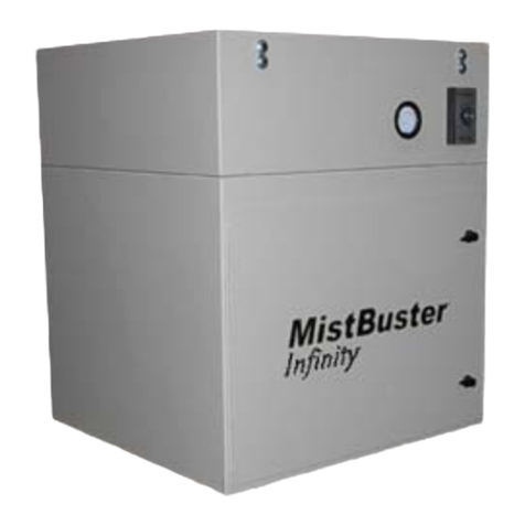
Air Quality Engineering MistBuster Infinity User manual

Air Quality Engineering
Air Quality Engineering SMOKEMASTER C-12 Instruction Manual

Air Quality Engineering
Air Quality Engineering M660 User manual

Air Quality Engineering
Air Quality Engineering MiracleAir CM-12 User manual

Air Quality Engineering
Air Quality Engineering AutoClean User manual

Air Quality Engineering
Air Quality Engineering XJ-2 User manual