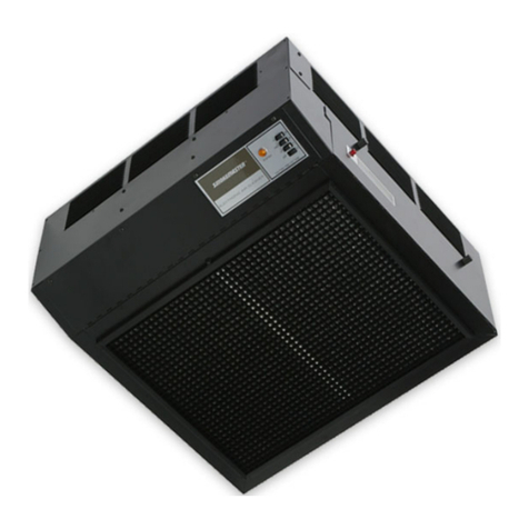
Air Quality Engineering MistBuster Infinity User manual

S U P P L Y I N G C L E A N A I R T O I N D U S T R Y
MistBuster®Infinity
Vertical Oil Mist Collector
The new MistBuster®Infinity from Air Quality Engineering, Inc.,
is a self-contained media air cleaning system designed for
source capturing coolant mist applications in industry. The MistBuster®Infinity
will effectively remove a broad range of contaminants including mist, smoke, soot,
vapors, VOC’s and more at a rate of up to 1000 cfm.
7140 Northland Drive North, Brooklyn Park, MN 55428-1520 USA
TOLL FREE: 1-800-328-0787
Air Quality Engineering Inc., has a policy of continuing product improvement and reserves the right to make changes
in design and specification without notice.

2
Before you get started please review the following:
Purchase Date: _____________________
Serial Number: _____________________
Type of oil / coolant collected: __________________________
Type of filter and AQE P/N: _______________________________________________
Customer Technical Support:
To contact Air Quality Engineering use:
Mail: Air Quality Engineering
7140 Northland Drive N.
Brooklyn Park, MN 55428
USA
Phone: 1.800.328.0787
763.531.9823
Fax: 763.531.9900
e-mail: [email protected]
web: www.air-quality-eng.com
Copyright
Air Quality Engineering, Inc. copyrights this manual with all rights reserved. Under the copyright laws, this
manual may not be reproduced in any form, in whole or in part, without the prior written consent of Air
Quality Engineering, Inc.
2004
Disclaimer
All statements, technical information and recommendations in this manual or related documents are
believed reliable, but the accuracy and completeness thereof are not guaranteed or warranted, and they
are not intended to be, nor should they be understood to be representation or warranties concerning the
products described.
Specifications are subject to change without notice.

3
TABLE OF CONTENTS
PAGE
HOW AIRBORNE CONTAMINATION IS REMOVED 3
DIMENSIONS 4
SPECIFICATIONS 4
AIR CLEANING BACKGROUND 5
INSTALLATION AND ASSEMBLY 6
CHECKOUT AND OPERATION 11
ELECTRICAL SCHEMATICS 12
MAINTENANCE 12
PARTS IMAGES 13
PARTS LIST 13
TROUBLE SHOOTING 14
WARRANTY 15
HOW AIRBORNE CONTAMINATION IS REMOVED
Dirty air passes through the impinger. The impingers remove large mist droplets. The primary filter then
captures the remaining smaller particulate. As the contaminant load on the filters increases, the filters
become more efficient in capturing the smaller particles. At the same time, however, the dirty filter allows
less particle collection and a decrease in the overall effectiveness of the air cleaner.

4
DIMENSIONS
METRIC CONVERSION FORMULA
Ins. to mm Ins. x 25.4
SPECIFICATIONS
- IMPORTANT -
THE SPECIFICATIONS GIVEN IN THIS PUBLICATION DO NOT INCLUDE NORMAL MANUFACTURING TOLERANCES.
THEREFORE, THIS UNIT MAY NOT MATCH THE LISTED SPECIFICATIONS EXACTLY. ALSO, THIS PRODUCT IS TESTED
AND CALIBRATED UNDER CLOSELY CONTROLLED CONDITIONS AND SOME MINOR DIFFERENCES IN PERFORMANCE
CAN BE EXPECTED IF THOSE CONDITIONS ARE CHANGED.
SPECIFICATIONS
Dimensions: 27.10”W x 26.25”L x 31.64” tall
Weight: 185 Lbs. installed weight
Cabinet: 16 gauge welded steel cabinet with a powder coat finish.
Standard Blower: Backward curved, vibration-free, direct drive rated at 1400 cfm @ 0” wg.
Instrumentation: Dirty Filter Gauge – Factory installed pressure gauge designed to determine filter
replacement cycle.
Power Input: 1.08 kW motor, 120V, 60 Hz, single phase, 9.4 amps
Impinger: Two 24” x 24” x 2” aluminum mesh grease impingers.
Primary Filter: One 95% DoP (288 square feet of media) oil long life mist filter
Air Quality Engineering, Inc., has a policy of continuing product improvement and reserves the right to make changes in design and
specifications without notice.

5
AIR CLEANING BACKGROUND
INTRODUCTION
Clean air is the subject of numerous laws and
regulations. Typical requirements in the United
States are those put out by the Occupational
Safety and Health Administration (OSHA). Private
groups, such as the American Society of Heating,
Refrigeration and Air Conditioning Engineers
(ASHRAE), have also published numerous
recommendations.
Normally, clean air is defined in regulations and
recommendations as air having a limited amount
of contaminant in it, commonly expressed as parts
per million or milligrams per cubic meter.
Approved counteractions are intended to lower or
eliminate the amount of contaminants in the air.
One of the more common methods of achieving
this goal is through the use of media air cleaners.
At no time should a media air cleaner be placed
where there is a potential for explosion due to the
presence of explosive dusts, gases or vapors.
Contact the nearest Air Quality Engineering, Inc.,
representative for assistance in determining the
correct application of a media air cleaner.

6
INSTALLATION AND ASSEMBLY
- CAUTION -
Do NOT connect the power source until after the
air cleaner is completely assembled.
If the air cleaner must be turned on for an
electrical check, be extremely careful in avoiding
electrical shock. Also, take care to avoid the air
cleaner’s moving parts.
INSPECTION
The MistBuster®Infinity air cleaner should be
checked for any shipping damage that may have
occurred during shipping. Any damage should be
noted and the carrier notified immediately.
TOOLS & EQUIPMENT REQUIRED
The following is a list of tools that would be needed
for typical installations:
•Reciprocating saw
•Drill
•Screwdriver
•Fork truck / Crane
PLANNING THE INSTALLATION
1. The MistBuster®Infinity mist collector
should be located with consideration for
convenience of maintenance and electrical
compartment access.
2. The filter access door on the MistBuster®
Infinity should not be obstructed. You need
a minimum of 26” clear in front of the filter
access door.
3. Mount the MistBuster®Infinity as far from the
chip conveyor opening as possible. This will
minimize the amount of clean outside shop air
from being drawn into the enclosure.
The MistBuster®Infinity can be mounted directly to
the enclosure on a machine tool. The collected
mist droplets simply drain back into the machine
tool through the air inlet of the MistBuster®Infinity.
INSTALLATION DIRECT MOUNT
Remove all filters from the MistBuster®Infinity.
Carefully position the MistBuster®Infinity on the
machine tool in the desired location. Refer to
Planning the Installation for guidelines in
positioning the MistBuster®Infinity on the machine
tool.
1. Use the inlet opening and the mounting hole
pattern on the bottom of the MistBuster®Infinity
as a template to mark the inlet opening and
holes to be drilled into the machine tool
enclosure. If the machine tool enclosure has
been designed with a provision for mist
collection, you may not need to cut an inlet
opening. NOTE: The inlet opening in the
machine tool does not need to be as large
as the inlet of the MistBuster®Infinity. It is
recommended that the inlet opening be a
minimum of 80 square inches.
2. Use a .437 diameter drill bit to drill the
mounting holes for the 3/8-16 bolts used to
secure the MistBuster®Infinity to the machine
tool.
3. There are four mounting holes in the
MistBuster®Infinity. It is recommended that a
minimum of four holes be drilled to secure the
MistBuster®Infinity to the machine tool.
Figure 2
7
4. Apply the gasket material provided on the
outside of the bolt holes. Overlap the gasket
on the corners. Carefully position the
MistBuster®Infinity over the opening and bolt
the unit in place.
5. The MistBuster®Infinity comes complete with a
10’ power cord. Plug the unit into an
appropriate grounded outlet.
6. Replace the mesh impingers and the main
filter. Please make sure the arrows on the
filters are pointing up.
Figure 3
INSTALLATION DUCTED
When direct mounting the MistBuster®Infinity is
impossible or not desired, the MistBuster®Infinity
can be installed with a plenum and ducting.
Ducted installation options will require our standard
plenum. The MistBuster®Infinity plenum has holes
on three sides and comes standard with two covers
and one eight-inch inlet collar.
Although we recommend direct mounting when
possible and minimizing duct length when ducting
is necessary, the MistBuster®Infinity can be
connected to multiple machine tools. Additional
ports can be ordered in 6” and 8” diameters.
INSTALLING THE PLENUM
1. Install the supplied covers and collar to the
plenum using the supplied silicone sealant and
#8 screws.
2. Attach the plenum to the inlet opening on the
MistBuster®Infinity using the supplied silicone
sealant and 1/4-20 bolts and nuts. Note that
the plenum may be rotated 180° for the desired
port orientation.
INSTALLING MACHINE MOUNT STAND
1. Remove the six 3/8-16 bolts on the back of the
MistBuster® Infinity and install the two L-
brackets.
2. Carefully drill the required six holes in the
machine tool to attach the L-brackets from the
machine mount stand using a 7/16” drill bit.
3. Use a crane or fork truck to lift the assembled
MistBuster®Infinity onto the machine tool.
- CAUTION -
Make sure the MistBuster®Infinity is secured
to the crane or forklift to avoid injury or
damage to the unit.
4. Bolt the MistBuster to the machine tool using
the supplied 3/8” nuts, bolts and lock washers.
6.006.00 6.00
3.07

8
Figure 4
INSTALLING CEILING MOUNT
- CAUTION -
The overhead structure must be strong
enough to support the weight of the
MistBuster®Infinity, plenum and ductwork.
Make sure that whenever using a fork truck,
hoist or lift that the MistBuster is properly
secured to prevent tipping.
Use caution not to damage the MistBuster
or plenum with the fork truck, hoist or lift.
1. Attach the four angle brackets to the front and
back of the MistBuster®Infinity using the eight
supplied 3/8-16 bolts and lock washers.
Fasten the four 3/8” eyebolts to the four
brackets using the supplied hardware.
2. Install the supplied covers and collar to the
plenum using the supplied silicone sealant and
#8 screws. Attach the plenum to the inlet
opening on the MistBuster®Infinity using the
supplied silicone sealant and 1/4-20 bolts and
nuts. Note that the plenum may be rotated
180° for the desired port orientation.
3. Install the MistBuster® Infinity using cable or
chain to suspend the unit from each eyebolt.
Make sure that the cable or chain is rated for
the appropriate weight of the MistBuster®
Infinity and accessories. Position the chains
or cables so that they form a 60° angle with
the top of the unit and a 45° angle from the
side surfaces. This will make the unit more
stable.
4. Level the MistBuster® Infinity in all directions.

9
INSTALLATION PEDESTAL STAND
- CAUTION -
The pedestal stand must be anchored to the
floor before it is assembled to the
MistBuster® Infinity.
Do not extend the top of the stand over 128”.
Level the stand before securing the anchor
bolts.
1. Slide the upper part (T-section) of the pedestal
stand into the lower section (lower section
contains the base which bolts to the floor).
2. Secure the base of the pedestal stand to the
floor using four 1/2” anchor bolts (not
supplied). Anchor bolts must be secured
before the MistBuster® Infinity is assembled to
the stand. Anchor bolts must extend 1 1/2”
above the floor to ensure adequate length.
3. Assemble the upper and lower pieces together
by inserting the four 3/8-16 x 3.5 inch long
bolts through the flat washers, lower section of
the stand and lock washers as pictured below.
To adjust the height of the pedestal stand,
loosen the four 3/8-16 x 3.5 inch long bolts
from the lower part of the stand and slide the
upper section to the desired height. Do not
adjust the top of the stand over 128” high.
Tighten the bolts to create enough tension to
secure the stand in place.
4. Remove the 3/8-16 bolts and lock washers
from the back of the MistBuster® Infinity.
Remove the electronic cell and impingers from
the MistBuster® Infinity and lift the unit up to
the pedestal stand. Align the MistBuster®
Infinity and insert and tighten the 1/4-20 bolts
with lock washers to secure the MistBuster®
Infinity to the pedestal stand. Install the
plenum per the instructions in the Installing
Plenum section.
5. Re-check all bolts to make sure they are
securely fastened.
Figure 6

DRAIN INSTALLATION
The MistBuster® Infinity plenum has a 1/2” female
pipe fitting drain that requires a P-trap and a drain
hose to return the metalworking fluid to the
machine tool.
Prime the P-trap with the metalworking fluid that
will be collected to avoid air being drawn through
the plenum drain.
Pipe Trap Coil Hose Trap
Minimum 8” Dia. Loop
Figure 7 – P-TRAP OPTIONS
ELECTRICAL INSTALLATION
- CAUTION -
All electrical work must be done by a qualified
electrician according to local codes.
Be certain that the power source is compatible
with the model ordered. See the rated voltage
on the inside of the filter access door.
Proper grounding of the MistBuster® Infinity is
essential for safety and operation.
Cord Connected
The MistBuster® Infinity is equipped with a 10-foot
power cord with a standard molded (15 amp rated)
plug. There must be a standard grounded outlet
provided within 10 feet of the MistBuster® Infinity.
Route the power cord so that it is out of the way of
the building’s occupants and so that it does not
interfere with the machine’s operation.
Conduit Connected
The MistBuster® Infinity can be hard wired. All
wiring must comply with applicable codes and
ordinances. All work must be done by a
qualified electrician.
The wiring compartment is on the right side of the
MistBuster® Infinity. Removing the side cover
accesses it.

11
CHECKOUT AND OPERATION
- WARNING -
The MistBuster®Infinity source capture Media Air
Cleaner is not explosion-proof. It must not be
installed where there is danger of vapor, gas or
dust explosion.
CHECKOUT
Before operating the MistBuster®Infinity, check
out the installation using the following procedures:
1. Make sure the air cleaner is oriented for good
air circulation where it will not interfere with
personnel and material traffic. Keep out of fire
lanes and away from overhead cranes.
2. Make sure the impinger and the primary filter
are properly oriented and the airflow arrows
are pointing toward the blower.
3. Make sure the minihelic is at zero inches of
water. If not, reference calibration of the
minihelic.
CALIBRATION OF THE SPEED CONTROLLER
1. Make sure power remains to the unit and the
filter access door is closed.
2. Adjust the speed of the blower to the lowest
setting.
3. Remove the dial by gently pulling it straight off.
4. Slide the plate down or up to see the fine tune
adjustment.
5. Locate the fine tune adjustment. It is a small
white screw head located near the speed
adjustment dial.
6. Using a small flat head screw driver turn this
adjustment so the blower is barely turning.
CALIBRATION OF THE MINIHELIC
1. Remove the plastic cover by turning it counter-
clockwise. One may have to press on the
cover as one is turning it.
2. With the supplied hex wrench, one can adjust
the needle by turning the hex screw at the
bottom of the gauge.
OPERATION
1. Turn on the air cleaner control switch. Make
sure the blower is providing a strong air
discharge. Please note that the MistBuster®
Infinity airflow is variable. Turning the dial will
change the airflow output.
2. The filter gauge should be level and should
read zero when the MistBuster®Infinity is
turned off.
3. The MistBuster®Infinity does not need to be
run at full speed. It should be set where it just
achieve negative pressure in the machining
area.
4. To do this, run the machining center with the
MistBuster®Infinity on the lowest speed to
create some mist. Open the machining center
door to see if mist escapes out the door.
5. Turn the dial on the MistBuster®Infinity to a
higher speed and repeat step 4.
6. Repeat this until no mist escapes out the door.

12
ELECTRAICAL SCHEMATIC
MAINTENANCE
- CAUTION -
Always disconnect the power to the MistBuster®
Infinity before working on or near the air cleaner.
FILTER MAINTENANCE/REPLACEMENT
Dirty air passes through the impinger. The
impinger removes large particulate. The primary
filter then captures the remaining particulate.
As the contaminant load on the filters increases,
the filters become more efficient in capturing the
smaller particles. At the same time, however, the
dirty filter allows less air to pass through resulting
in less particle collection and a decrease in the
overall effectiveness of the air cleaner.
The MistBuster®Infinity Air Cleaner is equipped
with a pressure gauge which indicates the
restriction to airflow caused by the filters loading
with particulate. When a noticeable reduction in
airflow occurs, it is time to clean or replace the
impinger and possibly the primary filter.
Turn off the air cleaner. Open up the filter access
doors and slide out the impinger.
Replace the impinger and turn on the air cleaner.
If no performance improvement is evident after
cleaning or replacing the impinger, the primary
filter will have to be replaced. In most cases, the
impinger can be replaced several times before the
primary filter will need to be replaced.
Replace the primary filter with the access door
open. The filter then can be removed by sliding it
out along the tracks. A new primary filter can be
replaced with the process reversed.
When replacing the primary filter this is also a
good time to check the blower. Remove the top
access cover to the unit. By hand rotate the
blower to see if there is anything obstructing
rotation.

13
PARTS IMAGES
PARTS LIST
NO. DESCRIPTION PART NO.
1 Filter ( 95% Mist Filter 24” x 24” x 12”) 41235
2 Impinger (Qty. 2) 41146
3 Impeller MistBuster Infinity 40073
4 MiniHelic 5” 10219
5 Speed Controller 10247
Not shown Plenum 07241
Not shown Impinger Assembly 07232
Not shown M69 Carbon Module 45 lbs. 07092
Not shown M68 HEPA Module 07091
Not shown Pedistal stand
Not shown Machine Mount stand

14
TROUBLE SHOOTING
WARNING!
The following instructions are intended for qualified service personnel only. Dangerous line
voltage circuits are exposed during this procedure.
First, make sure all electrical connections are good and double-check the wiring schematic to the unit
wiring.
The MistBuster®Infinity is not moving any air
Make sure the voltage is making it to the air cleaner.
After that make sure voltage is making it to the Speed Controller. If no voltage is at the Speed Controller
check the wiring before the speed controller
If voltage is making it to the speed controller with the speed controller in an on position check to see if
voltage is going through the speed controller. If no voltage is on the output side of the speed controller
then the speed controller needs to be replaced. Reference the parts list for replacement parts.
If voltage makes it past the speed controller check the motor.
(WARNING: disconnect power before the next step.) Check to see if anything is stopping the blower from
rotating. Try rotating it manually.
Make sure voltage is to the motor.
If voltage is to the motor and the motor still does not turn the motor needs to be replaced. Reference the
parts list for replacement parts.
The MistBuster®Infinity is not collecting the mist, it allows mist to pass through
Make sure the MistBuster®Infinity has filters properly installed in the filter tracks. If the filters are installed
properly remove the main filter and check the gasket for breaks or rolling. Check the filter media for
holes. If the filter needs to be replace for either of these reasons reference the parts list for replacement.

15
CERTIFICATE OF WARRANTY
THREE-YEAR LIMITED WARRANTY
Air Quality Engineering, Inc. (AQE), warrants to the original purchaser, subject to the conditions below, that if the
“Product” covered by this warranty should fail to perform by reason of improper workmanship or material, AQE will
during the period of three (3) years from the date of original purchase either (i) replace the product or (ii) provide all
necessary parts to repair the product without charge. The decision to replace the product or the necessary parts
shall rest solely with AQE. This three-year limited warranty does not apply to main filter elements. AQE will replace
without charge the main filter elements during the period of thirty (30) days from the date of original purchase if the
main filter elements fail to perform by reason of improper workmanship or material. This warranty is valid only under
the following conditions:
CONDITIONS
1. REGISTRATION: The purchaser’s completion and mailing of the Registration Card to Air Quality Engineering,
Inc., 7140 Northland Drive North, Minneapolis, Minnesota 55428-1520 within 30 days of original purchase.
2. AUTHORIZATION: The purchaser will contact AQE at (763) 531-9823 for authorization, returned goods number
(RGA) and the shipping address. AQE will direct the purchaser to either return the necessary parts or the
product at AQE’s option.
3. PROPER DELIVERY: The shipping, freight prepaid or delivery of the parts or the product to AQE in either its
original carton or in a carton assuring similar protection of the product with the returned goods number (RGA)
clearly displayed on the outside of the carton.
4. UNAUTHORIZED REPAIR: A showing by the original purchaser that the product has not been altered, repaired
or serviced by anyone other than an authorized service technician using genuine AQE parts.
5. UNAUTHORIZED PARTS: A showing by the original purchaser that the product has had only genuine AQE
parts and filters used in its operation and maintenance.
6. SERIAL NUMBER INTACT: A showing by the original purchaser that the serial number has not been altered or
removed.
7. MISUSE: A showing by the original purchaser that the product has not been involved in an accident, freight
damaged, misused, abused or operated contrary to the instructions contained in the Owner’s Manual.
Air Quality Engineering, Inc.’s, sole responsibility shall be to repair or replace the product within the terms stated
above. AQE SHALL NOT BE LIABLE FOR ANY CONSEQUENTIAL DAMAGES RESULTING FROM ANY BREACH
OF WARRANTY, EXPRESS OR IMPLIED, APPLICABLE TO THIS PRODUCT. Some states do not allow the
exclusion or limitation of consequential damages so this limitation may not apply to you.
THIS WARRANTY IS IN LIEU OF ALL OTHER WARRANTIES, EXPRESS OR IMPLIED, AND THE WARRANTIES
OF MERCHANTABILITY AND FITNESS FOR A PARTICULAR PURPOSE ARE HEREBY EXCLUDED BEYOND
THE THREE-YEAR DURATION OF THIS WARRANTY. Some states do not allow limitations on how long an implied
warranty lasts so the above limitation may not apply to you.
This warranty gives you specific legal rights and you may also have other rights that vary from state to state.
AIR QUALITY ENGINEERING, INC. TOLL FREE: 1-800-328-0787
7140 NORTHLAND DRIVE NORTH TELEPHONE: (763) 531-9823
MINNEAPOLIS, MINNESOTA 55428-1520 FAX: (763) 531-9900
MANUFACTURER & WORLDWIDE DISTRIBUTOR OF SMOKEMASTER® AIR CLEANING SYSTEMS
Printed in the USA
Table of contents
Other Air Quality Engineering Air Cleaner manuals

Air Quality Engineering
Air Quality Engineering Smokemaster User manual

Air Quality Engineering
Air Quality Engineering MiracleAir CM-12 User manual

Air Quality Engineering
Air Quality Engineering XJ-2 User manual

Air Quality Engineering
Air Quality Engineering SMOKEMASTER C-12 Instruction Manual

Air Quality Engineering
Air Quality Engineering M660 User manual

Air Quality Engineering
Air Quality Engineering Egg V2 User manual

Air Quality Engineering
Air Quality Engineering MistBuster 500 User manual

Air Quality Engineering
Air Quality Engineering AutoClean User manual