Air Quality Engineering Inc., has a policy of continuing product improvement and reserves the right to make changes in design and specification without notice.
PAGE
7
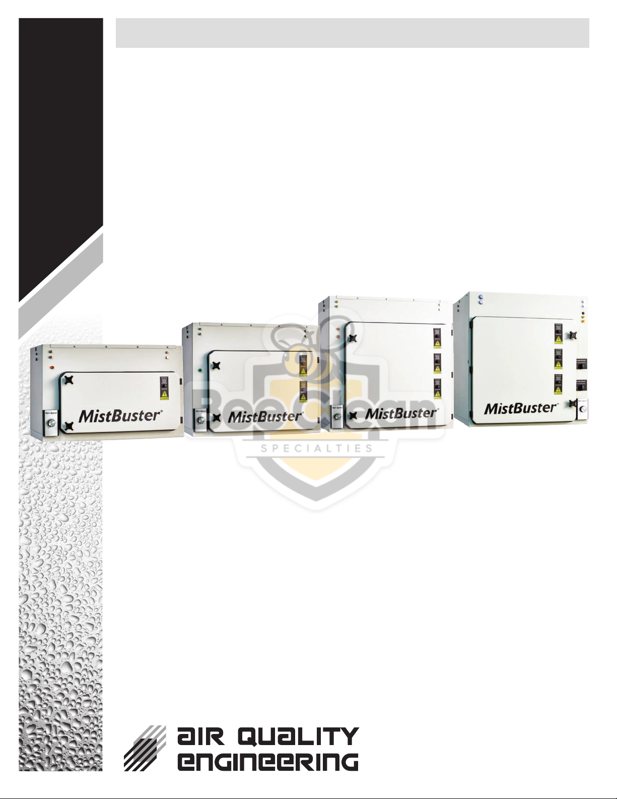
MistBuster®
7140 Northland Drive North, Minneapolis, MN 55428, USA
PHONE: 763-531-9823 • FAX: 763-531-9900 • TOLL FREE: 1-800-328-0787
EMAIL: info@air-quality-eng.com • www.air-quality-eng.com
Start Up
1. Start up the MistBuster by rotating the control
knob clockwise. Set the airflow at the
minimum airflow setting that will maintain
the proper negative pressure. In most cases,
the three o’clock setting on the speed
controller will provide enough airflow to
maintain negative pressure. This will reduce
noise and maintenance, and will increase
efficiency.
2. The performance indicator light should be on
when the blower is running.
3. Push the test button to momentarily short out the
collector on the electronic cells. Arcing indicates
that the cells are energized properly.
4. The coolant selector switch on the back of the
MistBuster is used to compensate for nuisance
arcing that occurs with some water soluble or
synthetics. Pull the knob out for the highest
voltage, if nuisance arcing occurs, push the
knob in.
CAUTION
1. Be extremely careful when working with
the electronic cell. The edges of the
collector plates and the ionizing wires on
the cell may be sharp.
2. When cleaning the cell, be sure to wear
appropriate protective gear, especially
goggles and gloves. Skin contact with
alkaline detergent solution should be
avoided. See warning label on the
detergent.
3. The electronic cell must be handled with
care to avoid damage.
The direct mount MistBuster captures mist
droplets from machine tools using either petroleum
or synthetic machining fluids. The collected fluids
drain directly back into the machine tool through
the inlet opening. This draining process actually
helps to keep the impingers and electronic cell
clean.
The mist impingers and electronic cell will need to
be cleaned periodically. The exact maintenance
interval is determined by each specific application.
Water soluble and synthetic machining fluids will
require more frequent cleaning than will petroleum
machining fluids. During the first few months of
operation, inspect the impingers and electronic
cell. When you have an excessive buildup on the
mist impingers and electronic cell, they will need to
be cleaned.
Parts Washer Method
The mist impingers and electronic cell can be
cleaned with a parts washer. Make sure that the
cleaning fluid used is aluminum safe and the
maximum pressure does not exceed 60 psi
[414kPa].
Manual Cleaning the Mist Impingers
Soak impingers in a solution of hot water and
alkaline detergent for 10-15 minutes. Thoroughly
rinse with hot water to remove any residual
detergent.
Manual Cleaning the Electronic Cell
1. Fill the wash tub with cell cleaning detergent
and hot water per the detergent
manufacturer’s instructions.
2. Immerse the cell in cleaner solution for five
minutes.
3. Thoroughly rinse the cell with very hot water.
Make certain no residue remains on the cell.
4. Inspect the collector plates for cleanliness.
Repeat wash procedure, if necessary. Check
for broken wires and bent collector plates.
The cell can be installed back into the
MistBuster. The indicator light may remain off
for the normal two hour drying time.
NOTE: If water-soluble machining fluids are
used, it would be best to coat the cell with AQE
Cell Coat after washing the cell. See the Parts
List section for the part numbers for the
detergent and cell coat.
Routine Maintenance