Air Solutions KK2 User manual

KK2 instruction manual - Issue 1.0
Use and Instruction Manual
Issue 1.0
RECOVERY, RECYCLING AND
RECHARGING STATION

Index
1. Introduction 3
1.1 Instructions 3
1.2 Safety regulations 3
2. Outfit 1
2.1 Standard outfit 1
2.2 Quick coupling with safety hand wheel 1
3. Use 1
3.1 Preparing for use 1
3.2 Control panel description 2
4. Functions of the recharging unit 3
4.1 Brief working cycle description. 3
4.1.1 Manual cycle 3
4.1.2 Automatic mode (no access to the database) 4
4.1.3 Automatic mode (with access to the database) 5
4.1.4 Special Functions 5
4.1.5 Setup. 6
4.1.6 Info 6
4.2 Analytical description of the cycles 8
4.2.1 Manual cycle 8
4.2.2 Automatic cycle 11
4.2.3 Automatic cycle (database) 12
4.3 Settings 12
4.3.1 Date/time setting 12
4.3.2 Internal gas tank recharging. 12
4.3.3 Tare test 13
4.3.4 Language 13
4.3.5 Databank update 13
4.3.6 LCD settings 14
4.4 Remarks 14
4.4.1 Vehicles with only one connection. 14
4.6.2 Oil reservoir emptying and filling 14
5. SPECIAL FUNCTIONS 15
5.1 Printing 15
5.2 Flushing (with refrigerant) 15
5.3 Nitrogen test 16
5.4 A/C system pressures test 16
6. Service 17
6.1 Dryer filters and vacuum pump oil 17
6.1.2 Oil replacement of vacuum pump. 18
6.2 Warranty 19
6.3 Spare parts and accessories 19
6.4 Service reminder 20
6.5 Warranty sheet 21
7. Technical data 22
8. EC declaration of conformity 23
Cooling gas R 134 recharge and recovery unit 23
KK2 MANUAL
2

1. Introduction
1.1 Instructions
This manual has been drawn up in order to assist you in using our recharging unit for A/C systems at
best and to protect your security...
We advise you to read the instructions carefully and to strictly comply with the given information.
We shall decline any responsibility resulting from the improper use of the equipment and any violation
whatsoever will cancel the guarantee.
Never position the recharging unit in a horizontal way, this would give rise to oil discharge from the
vacuum pump.
1.2 Safety regulations
Our recharging station is built in a way to be used by professionals adequately prepared for the use
and after having read the following safety regulations and instructions;
-use the recharging unit with gloves and protective glasses,
-avoid to inhale the gas,
-avoid the contact with the skin,
-avoid the contact with the eyes,
-do not smoke whilst using the recharging unit,
-do not use the unit near flames or sources of heat,
-do not use the unit in humid and wet environments,
-use the unit in airy environments,
-only employ original spare parte and accessories,
-do not fill the stocking reservoir above 80%,
-turn off all cocks before connecting to the A/C system,
-use the recharging unit only for gas R134a,
-during maintenance operations disconnect the unit from the electrical system,
-avoid to disconnect the connecting tubes if not necessary,
-Maintenance operations have to be carried out by specialized and authorized personnel.
Only use oil, additives or dye substances included in our catalogues or approved by our
company. The non-observance of this rule, will
Whatsoever damage due to a wrong or improper use of the station will not be covered by
our warranty. Consumables like packings and seals hoses and couplings, fuses and
gauges and damages occurred during transport are not part of the warranty
KK2 MANUAL
3

2. Outfit
2.1 Standard outfit
The standard outfit is always complete and of best quality:
n. 1 high pressure tube (red)
n. 1 low pressure tube (blue)
n. 1 Fitting for cylinder
n. 1 Quick coupling R134a high pressure (red).
n. 1 Quick coupling R134a low pressure (blue).
2.2 Quick coupling with safety hand wheel
The quick couplings have to be opened by screwing the hand wheels clockwise in order to avoid gas
dispersion into the environment (see figure 1)
It is recommended to empty the hoses and wait for some minutes before
disconnecting the quick couplings from the vehicle in order to avoid damages to
the seal rings of the connections
KK2 instruction manual - Issue 1.0
Fig. 1


3.2 Control panel description
Di
The control panel has been designed in a way that every operation to be carried out is easily intuitable
since all pressure gauges, buttons and cocks are coloured and equipped with symbols.
KK2 MANUAL
2
9
8
12 10
11
2
1
3
4 5
6
7
1
3
Fig. 3

1 – High pressure gauge: For the inspection and diagnosis of the A/C system.
2 – Low pressure gauge: For the inspection and diagnosis of the A/C system and for
the control of the vacuum.
3 - Tank pressure gauge: to check the pressure inside the stocking gas reservoir
4 - High pressure valve Connects the recharging unit to the A/C system.
5 - Low pressure valve: Connects the recharging unit to the A/C system.
6 - High pressure coupling Connects the cross-connection to the A/C system.
7 - Low pressure coupling Connects the cross-connection to the A/C system.
8 - Bias lighted display: Shows the operations of the unit on two lines.
9 - Button UP: Shows the operation of the unit and sets the time and the
quantity of gas and oil.
10 – Button DOWN: Shows the operation of the unit and sets the time and the
quantity of gas and oil.
11 – Button ENTER: Confirms the set operations.
12 – Button CANCEL interrupts any operation
13 – Serial port Used for yearly database updating
4. Functions of the recharging unit
4.1 Brief working cycle description.
When switched on, the unit displays the Database and allows the choice of a vehicle model to carry
out the working cycle (both in manual and in full automatic mode) with the help of the stored data
The choice of the vehicle is made by selecting PRODUCER – MODEL – YEAR OF CONSTRUCTION.
The database includes information regarding: A/C SYSTEM TYPE , OIL TYPE AND OVERALL
QUANTITY in the system compressor and sets the working cycle data according to the GAS
QUANTITY of the A/C system and the suggested vacuum and vacuum test times.
By pressing the button
©
it is instead possible to select the other functions of the unit:
- MANUAL OPERATION: allows to carry out working cycles, both in automatic mode (without access
to the database) and in manual mode i.e. one step after the other
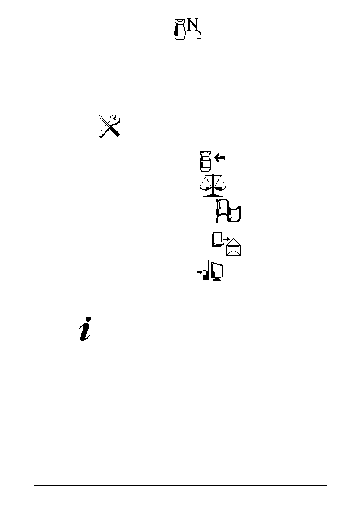
- SPECIAL FUNCTOINS: allows carrying out some additional functions such as a nitrogen pressure
test or a flushing cycle (with refrigerant)
- SETUP: allows to configure the unit and to update the database
- INFO: offers different information such as the number of carried out working cycles, the overall
quantity of recovered gas and the installed software version.
4.1.1 Manual cycle
With the help of the button ©, select MANUAL. With buttons it is possible to select
the following working cycles:
Description of the working cycle Symbol
KK2 MANUAL
3

Gas recovery, oil separation and drain.
Vacuum
Vacuum test
Oil injection
Dye injection
Gas recharging
The working cycle includes following phases:
Phase 1:Gas recovery from A/C system, gas residuals control and recovery, oil separation and oil
drain
Phase 2:Vacuum and vacuum test of the A/C system (the time is set by the operator).
Phase 3:Oil injection (by means of a solenoid valve)
Phase 4: Injection of the set dye quantity (by means of a solenoid valve).
Phase 5: Automatic gas recharging in the A/C system
With the use of the buttons
choose ENTER and the desired working phase and
press
↵
ENTER in order to modify the values. With buttons
modify the values, if necessary.
By pressing ENTER once, the working cycle will start- By pressing the button
©
, instead, the data
are stored without starting the working cycle immediately.
4.1.2 Automatic mode (no access to the database)
At the beginning, the last recalled car model is displayed. In order to work in automatic mode without
the use of the database, press
©
to go back to the function choice and select “MANUAL”. The
different working phase’s data are shown on the display
By selecting the icon
with the help of the buttons
and confirming with
↵
ENTER all working phases are carried out in automatic mode (according to the values shown on
display), i.e.
Description of the working cycle Symbol
KK2 MANUAL
4

Gas recovery, oil separation and drain.
Vacuum
Vacuum test
Oil injection
Dye injection
Gas recharging
In case it is necessary to change one or more of the shown values, proceed as follows:
-
select the working PHASE to be modified by means of the buttons
,
confirm with
“ENTER”, modify the values by means of the buttons
,
store the data by pressing ©, To
start the automatic cycle, select
and press
↵
ENTER.
4.1.3 Automatic mode (with access to the database)
At
the beginning, the last recalled car model is displayed. In order to work in automatic mode with the
use of the database select the desired vehicle model by means of
,
press
↵
ENTER to
reach the following menu, up to the final vehicle choice
Once the right vehicle has been se3ected, it is possible to start the full automatic mode by selecting
and pressing ENTER.
If, instead, it is necessary to modify one or more of the displayed values, proceed as described above
(see par. 4.1.2).
4.1.4 Special Functions
The special functions include:
a) The printing out of the working cycle data (optional)
b) The flushing cycle (with refrigerant) (optional)
KK2 MANUAL
5

c) The nitrogen pressure test (optional)
d) The working pressure test with pressure transducer for the Low Pressure side and
temperature probe (optional).
NOTE: for the use of the above special functions, the unit has to be ordered with additional
devices
4.1.5 Setup.
By selecting “setup” the following functions can be carried out:
Internal gas bottle recharging
Test of the electronic load cell
Language selection on display
Database updating
LCD display setting (this is carried out by the producer)
4.1.6 Info
By selecting the following statistic information are displayed:
a) Recharging station model
b) Software version
KK2 MANUAL
6

4.2 Analytical description of the cycles
4.2.1 Manual cycle
Phase 1: Refrigerant recovery from vehicle A/C system and oil separation
Open the main HP and LP valves (see par. 3.2 fig. 1) (VERTICAL position)
With the help of the button
©
and , select the MANUAL mode and press
↵
ENTER;
With the button select RECOVERY and press
↵
ENTER;
The recovery PHASE will start. Note: in case of an empty A/C system, a warning message will
be shown.
At the end of the recovery cycle the unit will display the recovered gas quantity and will
automatically check if there are still gas residuals in the A/C system by waiting for 2,30
minutes
Note: in case gas residuals are detected by the unit, a new recovery phase will automatically
start until the gas recovery is completed at the end of the cycle the unit will automatically drain
the recovered oil in the oil drain bottle (see fig. 2).
Phase 2: Vacuum and vacuum test (the length of the vacuum and of the vacuum test can be selected
by the operator):
Open the main HP and LP valves (VERTICAL position)
With the butons
©
and , select MANUAL and press
↵
ENTER;
With the button select VACUUM and press
↵
ENTER;
With the buttons choose the desired vacuum time (suggested min. vacuum time: from 20
to 30 minutes) and press
©
in order to store the data and follow with the vacuumj test time
selection (if the
↵
ENTER button is pressed at his point, the vacuum and the vacuummtest will
immediately start with the vacuum test time shown on the diplay);
With the help of the buttons
select VACUUM TEST
-
and press
↵
ENTER.
With buttons
choose the right vacuum test time (suggested time: from 3 to 5 Minutes) and
press
©
in order to store the data;
By means of the buttons
select VACUUM and, after having checked the working cycle
data, press ↵ENTER in order to start both the vacuum and the vacuum test cycles
The unit displays the time counter to the end of the cycle and the value of the pressure in the A/C
system (mar)
At the end of the vacuum time, the unit will automatically start the vacuum test time and display the

time remaining up to the end of the cycle and the pressure value the end of the cycle is signalised by a
warning tone...
ATTENTION: if, during the VACUUM TEST PHASE the pressure value increases and a leak in the
system can therefore be supposed, the unit warns the user by displaying a warning message and
emitting a continuous tone.
Phase 3: New oil / fluorescent dye injection
If necessary, at the end of the cycle, it is possible to inject new oil or/and fluorescent dye in the A/C
system. To inject the oil, follow the instructions:
Open the main HP and LP valves (see par. 3.2 fig. 1)(VERTICAL position)
With the buttons
©
and , select MANUAL and press ENTER;
ATTENTION: before proceeding with the Oil or dye injection check if the relevant containers (see page
14 fig. 1) are filled with a sufficient fluid quantity
With the buttens
select OIL INJECTION-
and press↵ENTER;
With
choose the desired quantity and press
↵
ENTER;
(it is suggested to inject 15 cc. more in comparison to the recovered quantity);
In order to inject fluorescent dye in the A/C system, proceed as described above with regard
to oil
injection, i.e.:
With the buttons
©
and , select MANUAL and press ENTER;
ATTENTION: before proceeding with the Oil or dye injection check if the relevant containers (see page
14 fig. 1) are filled with a sufficient fluid quantity
With the buttons
select DYE INJECTION
-
and press
↵
E
NTER;
With
choose the desired quantity and press
↵
ENTER;
(follow the dye producer’s suggestions on the quantity to be injected)
Phase 4: Refrigerant recharging into the A/C system:
Open the main HP and LP valves (see par. 3.2 fig. 1)(VERTICAL position)
With the buttons
©
and , select MANUAL and press
↵
ENTER
With select RECHARGING- and press
↵
ENTER
With the help of the buttons
choose the refrigerant quantity to be recharged in the
vehicle A/C system (in grams) and press
↵
ENTER
NOTE: During the VACUUM PHASE, the unit automatically heats the gas tank in order to increase and

hold the gas tank pressure between 6and 10 Bar. This will allow an easy and fast gas recharging
cycle, if the same is made before the pressure values decrease again. The gas tank pressure values
can be checked by means of the relevant gauge on the main control board
During the recharging PHASE, the unit continuously displays the recharged quantity until the selected
quantity has been reached. The end of the cycle is signalised by a continuous warning sound
NOTE: the gas recharging cycle is only made possible if the internal gas tank contains a min. quantity
of 600 g. of gas. Otherwise, a warning message- EMPTY GAS BOTTLE! - will be displayed and the
cycle will be interrupted.
IMPORTANT: The unit automatically calculates the gas quantity which will remain in the charging
hoses after the recharging cycle (approx.: 100 g.).At the end of the recharging cycle the unit twill ask
the operator to close the safety couplings to the vehicle LP and HP connections and, after the user
confirms by pressing on
↵
ENTER, proceeds automatically with the gas residual recovery from the
hoses.
Note: by pressing the button
©
every working cycle can be interrupted
Phase 5: High and low pressure control
Once the right refrigerant quantity has been recharged in the vehicle, it is possible to check the high
and low pressure values of the A/C system.
Connect the A/C system to the unit and open the safety couplings (fig. 1)
“Close” the main HP and LP valves (see par. 3.2 fig. 3)(HORIZONTAL position)
Start the engine, set the A/C system to the lowest temperature setting, .fan to max. speed, close
external air inlets Before starting the measurements, allow the A/C system to warm up for 3/5 minutes
Check the relevant pressure gauges for HP and LP values
Note: the unit is also foreseen for the low pressure control by means of a pressure transducer. This
allows displaying the value and, eventually printing it by means of the printer (optional). Select the
pressure test menu (see hereunder for an analytical description of the pressure test). It is also
possible to connect to a temperature probe (optional) in order to display the air temperature value.
Pressure table
Environment temp. (C°) Low pressure High pressure
R12 R134A R12 R134A
min Max. min Max. min Max min Max
15,5 0,5 - 2 0,5 - 2,5 9,1 - 11,2 6,5 - 10
18 0,5 - 2 0,5 - 2,5 9,8 - 12 7 - 12
22 0,5 - 2 0,5 - 2,5 10,5 - 12,7 8 - 14
30 0,5 - 3 0,5 - 2,5 12,7 - 15,5 10 - 17
35 0,5 - 3 0,5 - 2,5 14,5 - 17,5 11,5 - 20
40 0,5 - 3 0,5 - 3 17,1 - 20,5 14 - 22
Heater:
In order to allow an easy and fast recharging of the A/C system, the unit automatically heats the
internal gas tank during the vacuum phase and holds its pressure values between 6 and 10 Bar. .
The working pressure of the internal gas tank is therefore from 6 to10 Bar

4.2.2 Automatic cycle
Gas recovery and oil separation/drain, vacuum and vacuum test, new oil injection, dye injection,
refrigerant gas recharging.
IMPORTANT the unit automatically calculates the gas quantity which, at the end of the working cycle,
will remain in the charging hoses (100 g. approx.). At the end of the recharging phase, the user will be
therefore asked to close (=turn counter clockwise) the couplings to the A/C system and to confirm the
procedure with
↵
ENTER.
Open the main HP and LP valves (see par. 3.2 fig. 1) (VERTICAL position)
With the buttons © and , select MANUAL and press
↵
ENTER
The data relevant to the different working phases are shown on the display, i.e.:
RECOVERY , VACUUM , VACUUM TEST , OIL INJECTION ;
DYE INJECTION , GAS ERCHARGING .
If all the data are correct, select the AUTOMATIC cycle with the help of the buttons
and confirm with
↵
ENTER The unit will start the automatic working cycle according to
the data shown on the display
In case it is necessary to change the working data, act as follows.
With the help of the buttons select the working PHASE to be modified, press
↵
ENTER
, change the settings with the help of
,
exit and store the data pressing on
©
Once all changes have been made, select
and press .
↵
ENTER in order to start the
automatic cycle
The unit will begin with the refrigerant RECOVERY and the following oil separation phase.
Note. If no gas is detected in the lines, the unit displays “A/C system empty!” and switches to the
following cycle.
At the end of the recovery cycle, the unit drains the recovered oil parts in the oil bottle and waits for
2,30 in. in order to check if there are still gas residuals in the A/C system.
Note: In case gas residuals are detected by the unit, a new recovery phase is automatically started.
When the system has been completely emptied, the recovered oil is drained in the used oil bottle (see
fig. 4).
The unit then automatically switches to the VACUUM PHASE. The unit displays the time missing to the
end of the cycle and the pressure values in mBar
At the end of the vacuum phase, the unit starts the VACUUM TEST phase. On the display, the user
can read the current pressure value and the time count down.
If no leak detection has occurred during the VAC TEST, the unit injects the oil and (eventually) dye

quantity according to the previously set values. (See above page 11)
The last cycle is the RECHARGING PHASE. During the recharging, the unit displays the current,
recharged, gas quantity a number of tones warn the user that the complete working cycle has been
finished.
ATTENTION: if, during the VACUUM TEST PHASE, a leak is detected, the unit warns the operator
with a series of tones and stops the working cycle.
N
ote by the use of the button
©
the workig cycle can be interrupted at any time.
.At the end of the working cycle, it is possible to make an A/C system pressure test (see above)
4.2.3 Automatic cycle (database)
When you switch on the unit, the last recalled car model is shown on the display.
In order to work in automatic mode with the use of the database select the desired vehicle model by
means of
,
press
↵
ENTER to reach the following menu, up to the final vehicle choice
Once the right vehicle has been selected, it is possible to start the full automatic mode by selecting
and pressing ENTER.
If, instead, it is necessary to modify one or more of the displayed values, proceed as described above
(see par. 4.1.2).
4.3 Settings
4.3.1 Date/time setting
(the date and time settings are only necessary
If the unit is provided with a printer - (OPTIONAL).
4.3.2 Internal gas tank recharging.
If the gas quantity in the internal gas tank decreases too much, the unit warns the user to
recharge the tank before starting the working cycle. In order to recharge the gas tank, act as
follows::
Connect the RED/HP hose of the unit to the external gas tank, by means of the relevant adapter, part
of the outfit.
ATTENTION! If the external gas bottle is provided wit only ONE tap (usually a BLUE/LP tap) the unit
has to be reversed in upside-down position, in order to recover mainly liquid gas.
With the help of the buttons select SETTINGS and press
↵
ENTER

With the buttons select GAS TANK RECHARGING - and press
↵
ENTER
With set the gas quantity to be recharged in the internal tank and press
↵
ENTER
The unit automatically stops the recharging when the set quantity is reached
Close the coupling on the external gas bottle.
Close the quick coupling and recover the gas left in the hose.
4.3.3 Tare test
With the button
select - SETUP
-- an
d press
↵
ENTER
Pressing on
select TARE TEST
- an
d press
↵
ENTER
The unit twill display the current gas weight value on the top of the screen and the weight of the
sample at the bottom.
The user puts a known sample weight on the gas bottle (for instance a 2 Kg. sample) and the load cell
of the unit has to be periodically tested, at least once a year.
4.3.4 Language
It is possible to change the language setting of the unit s following described:
Using the button
select the option- SETUP
-- an
d press
↵
ENTER
Pres
s ,
select LANGUAGE
- an
d press
↵
ENTER
With the button
choose your language
an
d press
↵
ENTER
4.3.5 Databank update
(The data bank update has to be made by authorised personnel only).
Using the button
select the option- SETUP
--
and press
↵
ENTER
Connect your PC to the unit through the serial port of the unit (the unit has to be switched off, when
connecting)
Pres
s ,
select DATABANK UPDATE
an
d press
↵
ENTER
Start the update program on your PC following the instructions provided with the UPDATE CD-ROM.

4.3.6 LCD settings
(for production purposes only; the settings can not be changed by the user)
4.4 Remarks
4.4.1 Vehicles with only one connection.
For vehicles which have only one connection of high or low pressure the relevant tube and quick
coupling has to be used and the other cock has to be closed,.
After having carried out the above proceed with all the functions, as for a unit with two connections.
Example: Vehicle with only one connection of high pressure:
-- connect the quick coupling of high pressure (red) to the A/C system;
-- open cock of high pressure (red) and close the low pressure one (blue);
-Carry out the gas recovery phase as for a unit with 2 couplings.
4.6.2 Oil reservoir emptying and filling
Exhaust oil:
- Empty the bottle when the oil level is around 200/220 cc;
- Use adequate containers for the exhaust oil.
IMPORTANT: used oil is a special waste and has therefore to be treated in conformity with the
regulations in force
New oil:
The level should never be below 100 cc.
Synthetic R134a oil is recommended to be used for the system.
It is advisable to use types of oil which are recommended by the manufacturer of the A/C system
Dye:
The level should never be below 100 cc.
1) New oil container 2) Oil drain bottle
3) Dye fluid bottle
1
33
3
2
3
Fig. 4

IT IS RECCOMENDED TO USE AUTHORISED DYE FLUID ONLY. DAMAGES CAUSED
TO THE UNIT BY THE USE ON NON-AUTHORISED DYE FLUIDS WILL NOT BE
COVERED BY THE WARRANTY.
5. SPECIAL FUNCTIONS
5.1 Printing
(the printer is an OPTIONAL accessory which can be included in the unit or added to the unit by
authorised personnel)
In order to print the data of the last working cycle, select SPECIAL FUNCTIONS , PRINT and press ↵
ENTER
5.2 Flushing (with refrigerant)
REMARKS: the flushing cycle is only made possible when the unit has been prepared for this
purpose from the beginning and has been added with special parts. The flushing furthermore
foresees the use of optional accessories (connections and additional filters which are not
included in the standard outfit and have to be bought separately)
Close (i.e. put in horizontal position) the HP main cock, disconnect the HP hose and connect tot he
additional refrigerant outlet (optional part) (the valve has to be closed when not working. DANGER:
never open the valve if not necessary).
Connect the HP hose (connected to the internal gas tank) and the LP hose (connected to the usual LP
inlet) to the A/C system or parts of the <A/C system by means of the universal coupling set code :
70601000 (not included in the standard outfit)
Attention: the refrigerant used for the flushing cycle is recovered in the unit and needs
therefore to be filtered before being introduced in our unit. We recommend to use the filter
included in the set of accessories for flushing, code no, 70601000 according with the relevant
use instructions.
With the help of the buttons
select FLUSHING
and press
↵
ENTER
NOTE: It is necessary to make a vacuum cycle before starting the flushing phase in order to
avoid that ait is recovered in the internal gas tank.
Set the vacuum time by means of the buttons
(
suggested vacuum time is 5 min.) and the
vacuum test time (to check for leaks in the A/C system-suggested test time is from 1-3 min.)
With the buttons
set the required flushing time (suggested flushing time is 20 min.), open

the connection valve to the internal gas tank (HP hose and press ↵ENTER in order to start the
flushing cycle. The unit will display the time left to the end of the cycle. It is eventually possible to print
the flushing cycle data (see above for the use of the printer option)
5.3 Nitrogen test
REMARKS: the nitrogen test cycle is only made possible when the unit has been prepared for
this purpose from the beginning and has been added with special parts. The test furthermore
foresees the use of optional accessories which are not included in the standard outfit and have
to be bought separately
With the buttons
select NITROGEN TEST
-
and press
↵
ENTER
NOTE: It is suggested to make a vacuum cycle before starting the flushing phase.
Connect the external nitrogen bottle through a pressure reducer to the nitrogen inlet of the unit the
suggested nitrogen pressure is from 18 to 20 Bar
We recommend to use the nitrogen test accessories kit code no. 70600647. the kit includes a
one way nitrogen bottle,a pressure reducer and a connection hose with couplings.
Select the desired vacuum time (suggested vac. time: 5 min.), the length of the vacuum test time and
the nitrogen pressure test time (suggested time: 20 Min.).
The unit twill display the pressure value in the A/C system.
ATTENTION: in case the pressure drops under certain values, the unit will display a warning sign and
emit a continuous warning sound.
It is eventually possible to display the data of the pressure test (see above for instructions on how to
print out working data.
5.4 A/C system pressures test
Connect the unit to the A/C system and open the safety valves.
The main HP and LP ball valves have to be in “closed” position which means in horizontal
position.
Start the vehicle’s engine, select min. temperature, max. fan settings”. Let the engine warm up for
there to four minutes in order to allow the A/C system to reach the working pressures.
Check the High and Low pressure values by means of the relevant pressure gauge manometer (HP =
red, LP = Blue)
In addition, the Low Pressure value can be red on the display,.it is also possible to connect the unit to
a temperature probe (optional) and measure the temperature
REMARKS: the temperature probe is an optional accessory which is not included in the
standard version.

Table of contents