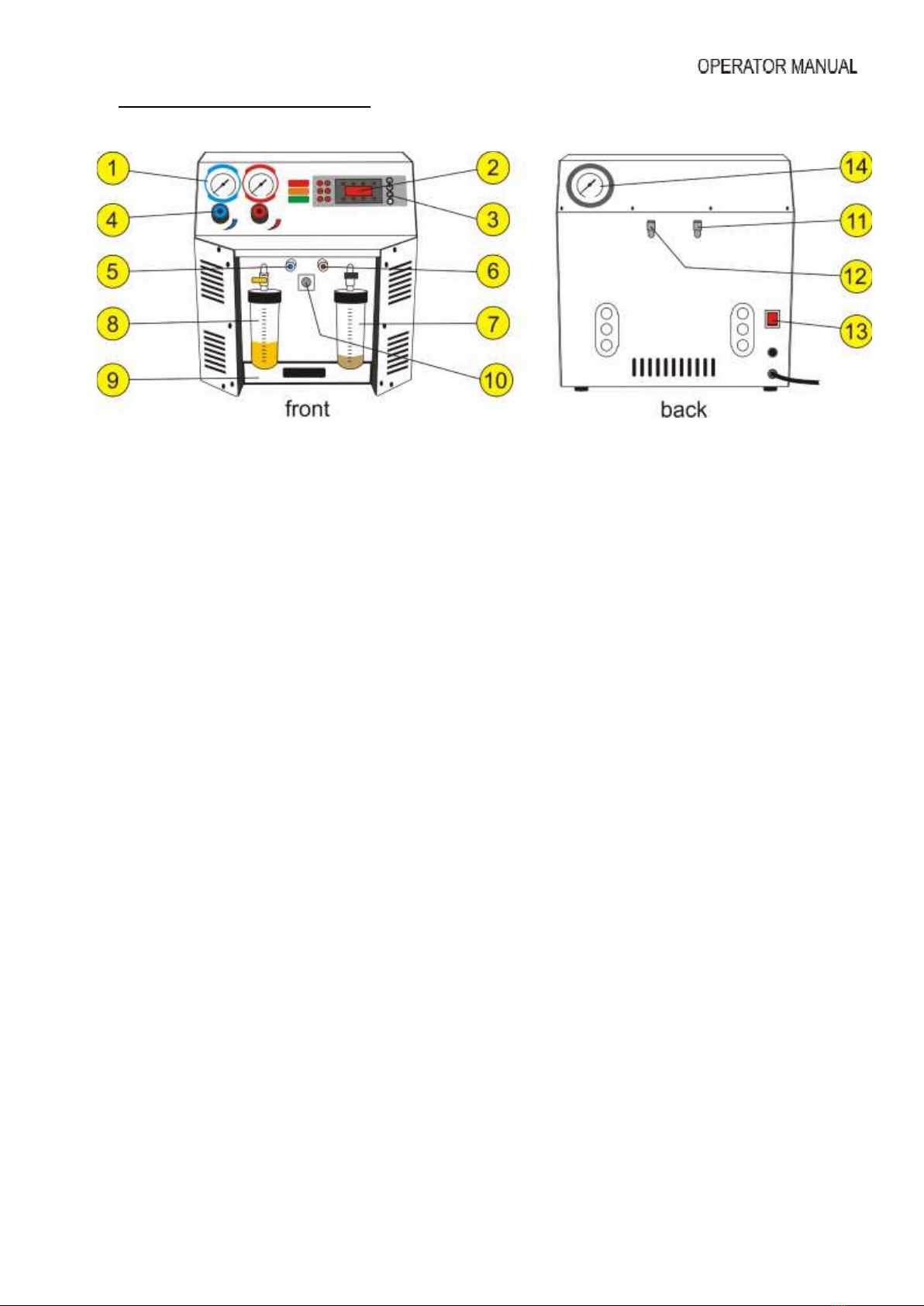
4. Main Parts & Features
1. Analog Gauges - Two large analogue gauges display suction and discharge pressures, which
are mounted on the front panel for easy viewing by the operator. Pressures are displayed in Bar &
PSI and temperatures in degrees Celsius.
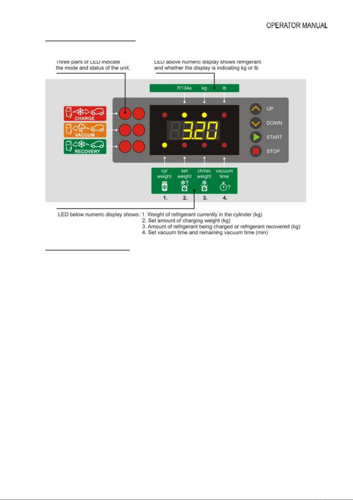
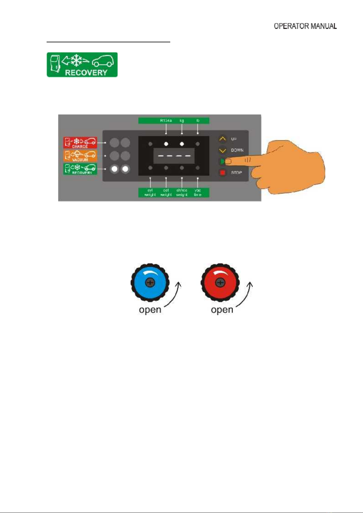
2. Display - Numerical display indicates the values and LED indicators above and below the
numeric display inform the operator whether the display is indicating kg or lb, remaining vacuum
time, weight of refrigerant currently within the cylinder, the amount of refrigerant being charged or
the amount of refrigerant recovered.
3. Mode Indicator -LED group and membrane switches. Three pairs of led blocks indicate the
mode and status of the unit. These are used in conjunction with the adjacent membrane switches
to select the unit functions. Further, once the mode is in operation the pattern in which the led’s
flash, indicate the activity of the system. These can be viewed from several meters.
4. Hand Valves -The console hand valves allow the operator to control the flow of the refrigerant
(if desired).
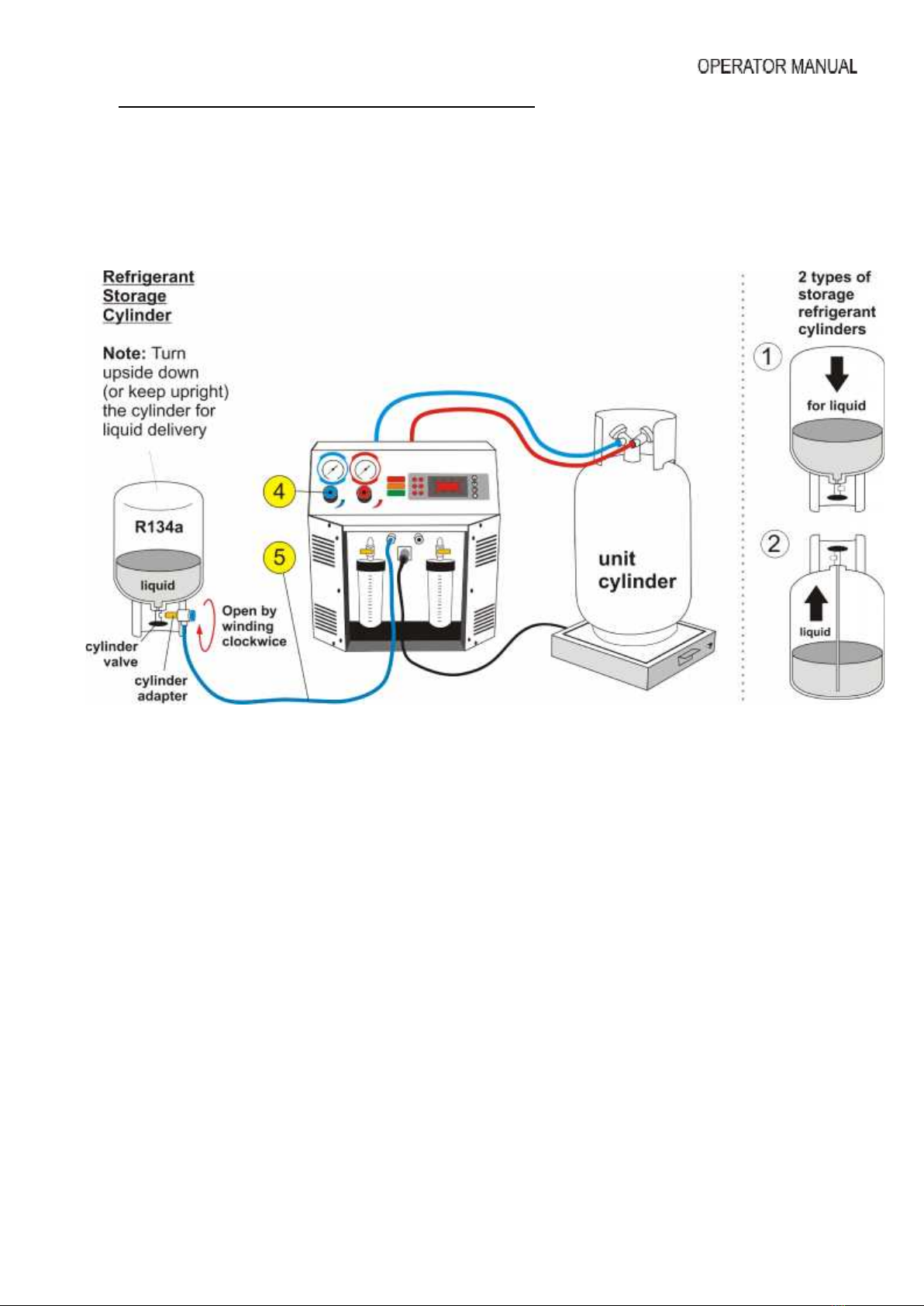
5. Suction (Blue) Service Hose Connecting Port – ¼” SAE.
6. Discharge (Red) Service Hose Connecting Port – ¼” SAE.
7. Recovered Oil Drain Reservoir -A vessel of 250ml (8.75oz) is mounted on the right front of
the unit to allow the operator to gauge the amount of oil recovered from the air conditioning
system, if any.
8. New Oil (and/or UV Dye) Storage Reservoir -A vessel of 250ml (8.75oz) is mounted on the
left front of the unit to allow the operator to inject oil into air conditioning system automatically.
9. Cylinder Platform / Electronic Scale
10. Five pin connector for Electronic scale
11. Cylinder vapor hose
12. Cylinder liquid hose
13. Power (switch, fuse, power lead)
14. Cylinder gauge