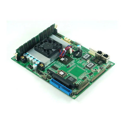
Aaeon PCM-6893 User manual

PCM-6893
Socket 370 based Tualatin/
Pentium®III/Celeron®
Comopact Board
W/LCD, Ethernet, Audio, & CFD

Compact Board PCM-6893
i
Copyright Notice
This document is copyrighted, 2003. All rights are reserved. The
original manufacturer reserves the right to make improvements to the
products described in this manual at any time without notice.
No part of this manual may be reproduced, copied, translated, or
transmitted in any form or by any means without the prior written
permission of the original manufacturer. Information provided in this
manual is intended to be accurate and reliable. However, the original
manufacturer assumes no responsibility for its use, or for any in-
fringements upon the rights of third parties which may result from its
use.
The material inthis document is for product information only and is
subject to change without notice. While reasonable efforts have
been made in the preparation of this document to assure its accuracy,
ENTRA, assumes no liabilities resulting from errors or omissions in
this document, or from the use of the information contained herein.
Aaeon reserves the right to make changes in the product design
without notice to its users.

Compact Board PCM-6893
ii
Acknowledgments
All other product names or trademarks are properties of their
respective owners.
Award is a trademark of Award Software International, Inc.
CompactFlash™is a trademark of the Compact Flash Association.
IBM, PC/AT, PS/2, and VGA are trademarks of International
Business Machines Corporation.
Intel and Pentium III are trademarks of Intel Corporation.
ITE is a trademark of Integrated Technology Express, Inc.
Microsoft Windows®is a registered trademark of Microsoft Corp.
TI is a trademark of Texax Insruments.
Cypress is a trademark of Cypress Semiconductor Corp.
LTC is a trademark of Linear Technology Corp.
Realtek is a trademark of Realtek Semiconductor Corp.
VIA is a trademark of VIA Technology, Inc.
AMD is a trademark of Advanced Micro Devices, Inc.
AMI is a trademark of American Megatrends, Inc.
Award is a trademark of Award Software International, Inc.
Cyrix is a trademark of Cyrix Corporation.
SMC is a trademark of Standard Microsystems Corporation.
RTL is a trademark of Realtek Semi-Conductor Co., Ltd.
C&T is a trademark of Chips and Technologies, Inc.
UMC is a trademark of United Microelectronics Corporation.
SiS is a trademark of Silicon Integrated Systems Corp.

Compact Board PCM-6893
iii
Packing List
Before you begin installing your card, please make sure that the
following materials have been packed:
•1 PCM-6893 Compact board
•1 Quick Installation Guide
•1 CD-ROM for manual (in PDF format), drivers
•Jumper kit
•Short copper and support
The PCM-6893requires several cables for operation. You can make
them yourself or purchase an optional cable kit.
If any of these items should be missing or damaged, contact your
distributor or sales representative immediately.

Compact Board PCM-6893
iv
Contents
Chapter 1 General Information
1.1 Introduction.........................................................................................1-2
1.2 Features................................................................................................1-3
1.3 Specifications.......................................................................................1-4
Chapter 2 Quick Installation Guide
2.1 Safety Precautions...............................................................................2-2
2.2 Location of Connectors and Jumpers.............................................2-3
2.3 Mechanical Drawing...........................................................................2-5
2.4 List of Jumpers....................................................................................2-7
2.5 List of Connectors..............................................................................2-8
2.6 Setting Jumpers...................................................................................2-10
2.7 LVDS Voltage Select (J1)................................................................2-11
2.8 LCD SHIFT CLOCK Select (J2) ..................................................2-11
2.9 DOC ADDRESS Select (J3) ......................................................... 2-12
2.10 WDT Status Setup (J4) .................................................................2-12
2.11 Serial Port 3 RING Status Setup (J5) ........................................ 2-13
2.12 Serial Port 4 RING Status Setup (J6) ........................................ 2-13
2.13 Serial Port 2 Status Setup (J7) ......................................................2-13
2.14 Serial Port 2 Status Setup (J8) ......................................................2-14
2.15 Serial Port 2 Status Setup (J9) ..................................................... 2-14
2.16 COMS Status Setup (JBAT1) .......................................................2-15
2.17 TV Output Connector (CN1) ......................................................2-15
2.18 LAN1 Status Connector (CN2) ................................................... 2-15

Compact Board PCM-6893
v
2.19Primary LCD Panel Connector (CN3) ...................................... 2-16
2.20 Secondary LCD Panel Connector (CN4) .................................. 2-17
2.21 Audio Output Connector (CN5) ................................................ 2-17
2.22 Serial Port 1 / 2 / 3 / 4 Connector (CN6) ............................... 2-18
2.23 Keyboard PS/2 Mouse Connector (CN7) ................................. 2-19
2.24 GPIO Connector (CN8) ................................................................2-19
2.25 Front Panel Connector (CN9) ..................................................... 2-19
2.26 CRT Display Connector (VGA1) ................................................ 2-20
2.27 LVDS Connector (LVDS1) .......................................................... 2-20
2.28 LVDS Connector (LVDS2) .......................................................... 2-21
2.29 10/100Base-Tx Ethernet Connector (LAN1) ........................... 2-21
2.30 Primary Device Connector Standard (IDE1) ............................ 2-22
2.31 Compact Flash Connector Standard (CF1) ............................... 2-24
2.32 ATX Power Connectors (PWR1) ............................................... 2-25
2.33 AT Power Connector (PWR2) .................................................... 2-25
2.34 CPU Fan Connector (FAN1) ...................................................... 2-26
2.35 Printer Port Connector (LPT1) ................................................... 2-26
2.36 Wake On Lan / Ring Connector (WOL1) ................................ 2-27
2.37 Floppy Connector Standard ......................................................... 2-27
2.38 USB Connector (USB1/USB2) ................................................... 2-29
2.39 IrDA Connector (IR1) .................................................................. 2-30
Chapter 3 Award BIOS Setup
3.1 System Test and Initialization............................................................ 3-2
3.2 Award BIOS Setup...............................................................................3-3
3.3Standard CMOS Features....................................................................3-6

Compact Board PCM-6893
vi
3.4Advanced BIOS Features....................................................................3-7
3.5Advanced Chipset Features.................................................................3-8
3.6Integrated peripherals...........................................................................3-9
3.7Power Management Setup.................................................................3-10
3.8PnP/PCI Configurations...................................................................3-11
3.9PC Health Status.................................................................................3-12
3.10 Load Fail-safe Defaults....................................................................3-13
3.11 Load Optimized Defaults................................................................3-13
3.12 Set Supervisor Password..................................................................3-13
3.13 Set User Password............................................................................3-14
3.14 Save and Exit Setup..........................................................................3-14
3.15 Exit without saving...........................................................................3-14
Chapter 4 Driver Installation
4.1 Installation 1..........................................................................................4-2
4.2 Installation 2..........................................................................................4-3
Appendix A Programming the Watchdog Timer
A.1 Watchdog timer of PCM-6893 .........................................................A-2
A.2Configuring Sequence Description...................................................A-2

Compact Board PCM-6893
Chapter 1 General Information 1-1
General
Information
Chapter
1

Compact Board PCM-6893
Chapter 1 General Information
1 -2
1.1 Introduction
Aaeon new compact size board PCM-6893 targets high-end
multimedia and networking applications. Easy Upgrading allows you
to take full advantage of Intel®Development of even-higher speed
Tualatin, Pentium®III and Celeron®processors. This is a perfect
choice for embedded applications that require cost-effective,high
computing performance features.
This board offers two alternatives of power supply type: AT and
ATX. You can select whichever suitable for your application. ATX
power consumption. It complies with the ACPI standard and
supports three types of power-saving features: Doze mode, Standby
and Suspend modes. The board watchdog timer automatically resets
the system or generates an interrupt in case the system stops due to a
program bug or EMI.
The onboard Compact Flash will offer a larger memory bank for data
storage of all types. CompactFlash requires a fraction of power used
to drive floppy disk or CD-ROMs, also no battery is required to save
the data when the computer powers down.
The PCM6893comes with VIA 8606 Twister T North Bridge
integrated AGP 4x 2D/3D graphics accelerator. With 36-bit dual
channel LVDS interface and TTL signal, you can utilize this board to
display CRT and up to 36-bit TFT LCD panels.
The onboard 10/100BaseTx Ethernet interface and Sound
Blaster-compatible audio opens up worlds of possibilities for kiosks,
gaming systems, POS systems, medical and educational products. The
Fast Ethernet controller provides a tenfold increase in Network
capability,and is fully compatible with traditional 10Mbps network
facilities.
PCM-6893 also includes four high-speed serial ports (three RS-232,
one RS-232/422/485), one multimode (ECP/EPP/SPP) parallel port,
2 floppy drives, four USB ports, an Ultra DMA/33 enhanced IDE
controller supporting up to two devices with data transfer rate up to
33MB per second, and a keyboard/PS/2 mouse interface. This
Aaeon embedded PC includes almost everything you need for fast,
worry-free embedded PC performance.
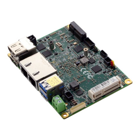
Compact Board PCM-6893
Chapter 1 General Information
1 -3
The addition of PC/104 connector allowsa wide selection of
accessory cards to be added to the PCM-6893. Such accessories as
Audio, fax modem, vehicle power supply, extra DiskOnChip,
PCMCIA module, etc.
1.2Features
nSupports socket 370 VIA C3 and Intel ® Celeron and
Pentium ® III/ III-M(Tualatin) processors.
nHigh Speed AGP 4X for VGA display.
nVT8606 Integrated 2D/3D graphics accelerator supports
up to 36-bit DSTN/TFT flat panel.
nVT8606 Integrated 2D/3D graphics accelerator,
Integrate 36 bit dual-channel LVDS Interface.
nVIA VT1621 Support NTSC/PAL TV OUT format.
nOne 10/100Base-T Fast Ethernet.
nSupports H/W status monitoring.
nALC AC97 ver. 2.2 SoundBlaster compliant Interface.
nSupports CompactFlash memory storage.
nFour USB Ports.
nDigital I/O

Compact Board PCM-6893
Chapter 1 General Information
1 -4
1.3 Specifications
System
lCPU: Socket 370 basedVIA C3 and
Intel®Celeron and Pentium®III
/III(Tualatin) Processors to 1.4GHz
lMemory:SDRAM DIMM Socket x 1, Max
512MB (PC-100/133 supported)
lSocket: 370 Pin Socket
lChipset: VIA Twister-T VT8606T
lChipset I/O: VIA 82686B/Winbond W83977TF
lBIOS: Award 2 Mb FLASH BIOS
lAudio: ALC201A CodecAC97, Mic in, Line
in, Line out
lSSD: One 32 Pin DIP socket supports
M-systems Disk On Chip 2000
Series up to 144MB
lCF: One CF Type II socket supports
Type I/II
lWatchdog timer: Can generate a systemReset, IRQ 15
or NMI. Software selectable
time-out interval (1sec~255 sec,
1sec/step )
lDMA: 7 DMA channels (8237 equivalent)
lPCI: PCI Ver. 2.2 compliant interface

Compact Board PCM-6893
Chapter 1 General Information
1 -5
One Standard 120Pin PCI connector
lPower Management: Supports PC97,APM 1.2 ACPI
compliant
lInterrupt: 15 interrupt levels (8259 equivalent)
lEthernet: Realtek8139DL Fast Ethernet c
controllers. IEEE 802.3
10BASE-T/100BASE-TX compliant
physical layer interface. One RJ-45
connector
lExpansion Interface: PC/104 x 1 PCI slot x 1
lBattery: Lithium battery for data retention,
DIP Type.
lPower supply voltage: Standard AT/ATX
Type, +5Vand +12V.
lOperating temperature:32 to 140 °F (0 to 60°C)
lBoard size/Weight:8" (L) x 5.75" (W) (203 mm x 146
mm)
Display
PCM-6893
lChipset: VIA VT8606
lMemory size: Share memory up to 32MB
lCRT: Resolution 1280 X 1024 X 32at
85Hz.Box Header 2x8.pitch 2.54mm
lTV out:Support NTSC/PAL TV OUT
Format,Pin Header 2x4.picth 2.0mm

Compact Board PCM-6893
Chapter 1 General Information
1 -6
lLVDS: Integrate 36 bit Dual-channel LVDS
Interface.One Pin Header 2x10,pitch
2.0mm.One Pin Header 2x9,pitch
2.0mm
lLCD: Integrate 36 bit DSTN/TFT flat
panel Interface. One DF-13 40Pin.
One DF-13 20Pin
I/O
lDigital I/O: Support 4 in / out digital I/O each
with TTL level interface.Pin Header
2x5.pitch 2.0mm
lIR interface: Supports One IrDA Tx/Rx header
Pin Header 1x5.pitch 2.54mm
lIDE interface: 1 IDE connectors support up to 2
IDE devices, also support Ultra33
with data transfer rate up to
33MB/s ,Box Header 2x22.pitch is
2.0mm.
lAudio Interface: AC97 Ver. 2.2 compliant interface
MIC-IN,LINE-OUT,LINE-IN
Box Header 2x7.pitch 2.54mm
lSerial Interface: Three RS-232 and One
RS-232/422/485 Serial Ports
Pin Header 2x20.pitch is 2.54mm
lParallel Port: One bi-directional parallel port.

Compact Board PCM-6893
Chapter 1 General Information
1 -7
Support SPP,ECP,and EPP modes
Box Header 2x13,pitch is 2.54mm
lFLOPPY: Support up to two floppy disk
drives,5,25” (360KB and 1.2MB)
and /or 3.5” (720KB, 1.44MB, and
2.88M),Pin Header 2x17 pitch is
2.54mm
lUSB: Compliant with USB 1.1 Two Pin
Headers 2x4,pitch 2.54mm Support
4 USB ports
lKB/Mouse: Support PS/2 keyboard and
mouse.Pin Header 2x4-1,pitch
2.54mm

Compact Board PCM-6893
Chapter 2 Quick InstallationGuide
Quick
Installation
Guide
Chapter
2
Part No. 2007689310 V.1 Printed in Taiwan 6/ 2003

Compact Board PCM-6893
Chapter 2 Quick Installation Guide
2 -2
2.1 Safety Precautions
Always completely disconnect the power cord from
your board whenever you are working on it. Do not
make connections while the power is on, because a
sudden rush of power can damage sensitive
electronic components.
Always ground yourself to remove any static charge
before touching the board. Modern electronic
devices are very sensitive to static electric charges.
Use a grounding wrist strap at all times. Place all
electronic components on a static-dissipative surface
or in astatic-shielded bag when they are not in the
chassis

Compact Board PCM-6893
Chapter 2 Quick Installation Guide
2
-
3
2.2Location of Connectors and Jumpers
Locating connectorsand jumpers (component side)
S3-VIA
BATTERY
VIA
BIOS
PGA370
WOL1
PCI1
DIMM1
J1
J2
CN3
LVDS2
LVDS1
CN4
CN1
JBAT1
PWR1
CD_IN1
CN2
LAN1
VGA1
CN6
CN5
LPT1
FDC1
J3
CN7
J7
J8
J9
J6
J5
J4
IDE1
CN9
CN8
IR1
USB2
USB1
FAN1
SLOT1

Compact Board PCM-6893
Chapter 2 Quick Installation Guide
2
-
4
Locating connector (solder side)
CF1

Compact Board PCM-6893
Chapter 2 Quick Installation Guide
2
-
5
2.3 Mechanical Drawing
Mechanical drawing (component side)
5.08
0.00
5.08
16.83
130.18
143.51
161.23
166.31
198.12
203.20
90.17
146.05
140.97
115.57
5.08
13.97
65.41
69.85
95.89
140.97
198.12
193.04
99.06
88.90
66.68
171.94
50.48
5.08
106.68
180.34
106.05
124.46
139.07
127.64
71.76
53.53
85.82
S3-VIA
BATTERY
VIA
BIOS
20.32
15.24
100.97
189.87
186.69
176.47
171.39
181.55
182.88
99.06
102.87
111.76
114.30
104.14
1.27
1.91
3.18
8.89
144.78
139.53
130.38
127.43
139.07
141.40
143.09
3.81
28.58
27.94
186.06
190.50
200.03
PGA370
0.00

Compact Board PCM-6893
Chapter 2 Quick Installation Guide
2
-
6
Mechanical Drawing (solder side)
0.00
5.08
5.08
203.20
198.12
182.88
5.08
15.24
102.87
5.08
140.97
146.05
0.00
198.12
140.97
100.97
180.34
106.68
55.32
173.67
158.12
Other manuals for PCM-6893
2
Table of contents
Other Aaeon Motherboard manuals

Aaeon
Aaeon MIX-H310D1 User manual

Aaeon
Aaeon GENE-CV05 User manual

Aaeon
Aaeon GENE-QM77 User manual

Aaeon
Aaeon HSB-910I User manual

Aaeon
Aaeon GENE-U15B User manual

Aaeon
Aaeon EPIC-QM77 User manual

Aaeon
Aaeon Raptor MicroATX User manual

Aaeon
Aaeon PCM-5896 User manual

Aaeon
Aaeon FWB-2250 User manual

Aaeon
Aaeon PCM-6897/L User manual

Aaeon
Aaeon PCM-6890 User manual

Aaeon
Aaeon COM-45GS User manual

Aaeon
Aaeon SBC-658 User manual

Aaeon
Aaeon MPC-8890 User manual

Aaeon
Aaeon ?COM-BT User manual

Aaeon
Aaeon SBC-590 User manual

Aaeon
Aaeon GENE-WHU6 User manual

Aaeon
Aaeon GENE-A55E User manual

Aaeon
Aaeon EMB-H81A User manual

Aaeon
Aaeon PCM-4897 User manual