AirBench AOF User manual

© Copyright AirBench Ltd 2021 Page
1 of 24
AOF
Installation Manual
This Edition: 20th September 2022
Please ensure this manual is read and understood fully prior to installation
Damage may be caused to the unit if instructions are not followed correctly
AirBench Ltd, 6b Commerce Way, Colchester CO2 8HR
www.airbench.com
+44 (0) 1206 791191
AIRBENCH LTD

© Copyright AirBench Ltd 2021 Page
2 of 24
INTRODUCTION 4
OVERVIEW 4
ABOUT AOF 4
ABOUT THIS DOCUMENT 4
SCOPE OF SUPPLY 5
INSTALLATION 7
GENERAL 7
415V 3 PHASE WIRING ALTERATION & LED POWER CONFIGURATION 8
INSTALLATION GUIDE 11
ADJUSTMENT OF LED WARNING INDICATORS 15
COMMISSIONING 17
TROUBLESHOOTING 18
AIRBENCH LTD

© Copyright AirBench Ltd 2021 Page
3 of 24
CAUTIONS
Do not place this product near a powerful magnetic field or expose to static
electricity.
Do not drop unit or damage the unit body.
This unit is not ATEX rated.
It is your responsibility under ATEX regulations to ensure this unit is located in an
area which is rated as suitable for the specification of the unit.
We do not accept responsibility for any inconvenience or damage caused by
unusual or unspecified applications. If the product is damaged or service is
required, please contact us.

© Copyright AirBench Ltd 2021 Page
4 of 24
Introduction
Overview
Thank you for choosing AirBench AOF as your mist control system. Please read this document before
installation.
This document details installation activities which are essential to correctly install your AOF. We
recommend that the Responsible Person reads this manual fully prior to installation and operation of
the AOF.
This document refers to the AOF range. Models of this type are available with a range of filter
configurations. The filter configuration in use is detailed on the system Commissioning Certificate and
on order.
About AOF
AirBench AOF is a dedicated coolant mist / smoke filter system designed for installation to machine
tools, for the removal of contaminants from most types of machining.
AOF is currently patent pending.
About this Document
This document provides full installation instructions for the AOF range. It should be read in
conjunction with the Commissioning Certificate supplied on installation. If you have any concerns or
doubts about the installation of this unit, contact the supplier.

© Copyright AirBench Ltd 2021 Page
5 of 24
Scope Of Supply
Name
Quantity
Air inlet adaptor
1
Flexible hose clamp
2
Jacob Hose Connector
2
Jacob Clamp
2
Jacob U-Seal
2
Anti-vibration mount 8 or 10mm
4

© Copyright AirBench Ltd 2021 Page
6 of 24
Flexible hose
1.5M
1
1.25 four-core oil proof cable 3.3M
1
Oil drain hose 3M
1
Pre-installed
Power switch (optional)
1

© Copyright AirBench Ltd 2021 Page
7 of 24
Installation
General
•Installation must only be performed by an authorized Technician/Electrician who has carefully
read the installation guide. This is to prevent electric shock or damage to the machine and a
trouble free installation.
•To ensure correct performance, the air cleaner should be properly installed on the machine
tool. The installation area must be stable and vibration-resistant. If the machine is not capable
of supporting the weight of the AOF, use a stand or mount to a wall.
•To maintain efficiency, maintain high bend radius in hoses.
•The electric wiring must comply with electrical standards and should be completed by a
qualified and competent Electrician or Technician.
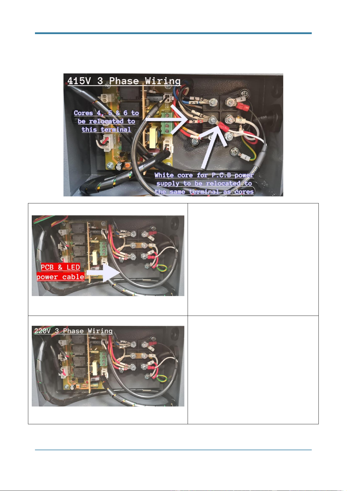
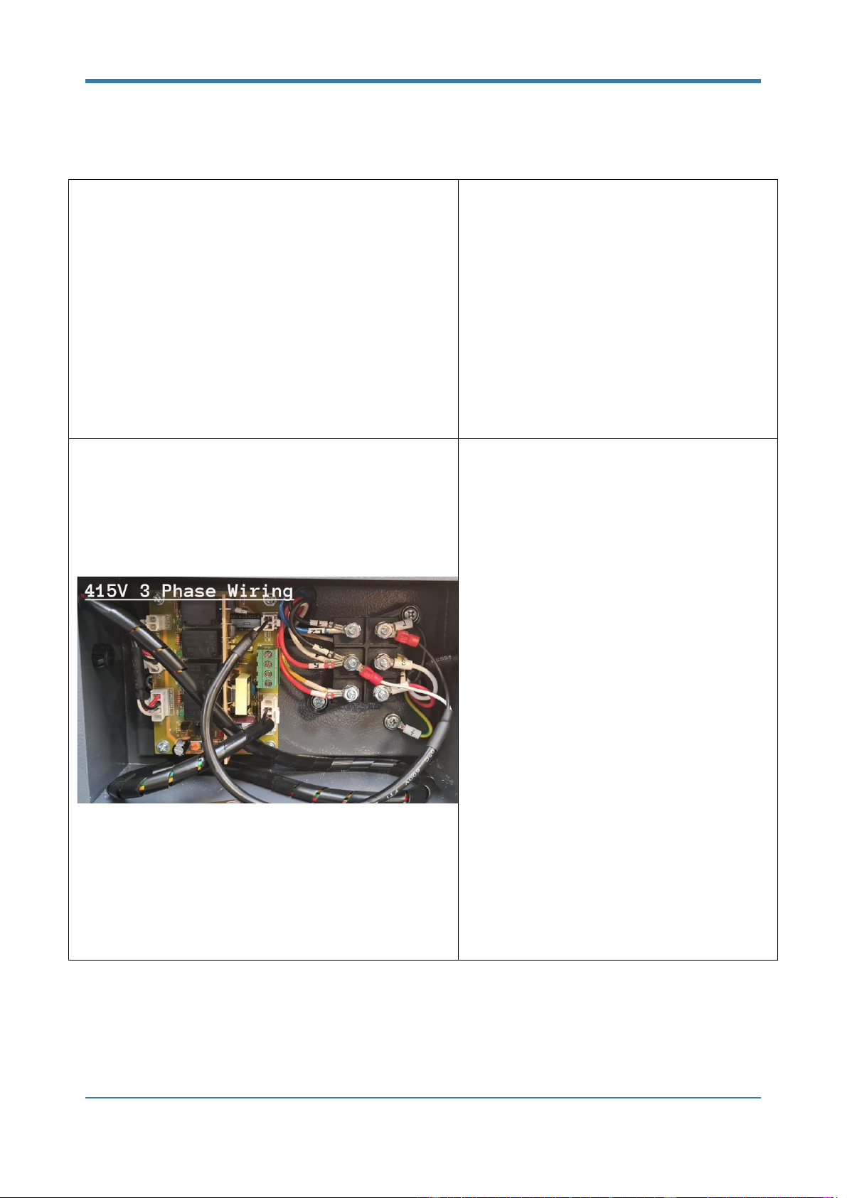
•Our AOF units come pre-wired for 220V 3 phase supply (220/3/50) and may also be
configured for 415V 3 phase (415/3/50). For further electrical information, refer to the
following guidance in this manual.
•When installing the unit, motor / overload protection must be provided. A suitably sized DOL
starter or motor protection circuit breaker should be used.
•Do not change the power wire length or use extension wire.
•After installation, the installer should complete commissioning tests as detailed within this
document.

© Copyright AirBench Ltd 2021 Page
8 of 24
415V 3 Phase wiring alteration & LED power
configuration
Please ensure that the following instructions are read and understood fully before beginning
installation, installation should only be carried out by a trained and competent person.
Failure to do this will result in damage to the unit
When changing supply voltage from 220V 3 Phase to 415V 3 Phase the following alterations are
required to the internal wiring.
AOF internal wiring change for 415V 3PH supply
1. Remove back plate to gain access to electrical terminal box
2. Remove 6 x screws from electrical terminal box and remove cover
3. Remove plastic terminal cover
4. Loosen and remove the required terminal nuts to enable relocation of motor connections
5. Remove brass connecting bar
6. Locate cores 5 & 6 and remove from original terminals
7. Re-terminate cores 5 & 6 with core 4 to LHS middle terminal
8. Re-terminate white P.C.B supply core with cores 4, 5 & 6
9. Tighten all connections ensure cores are terminated at the correct terminals
10. Refit plastic terminal cover
11. Refit terminal box lid ensuring seal is fitted
12. Refit back plate

© Copyright AirBench Ltd 2021 Page
9 of 24
Phase change on AOF units with L.E.D
indication
From the P.C.B you will see the 2 core LED
PCB power cable (arrowed) which will need to
be configured to the correct voltage being
supplied to the mist filter.
Please see below for wiring configurations for
both 220v 3 phase and 415v 3 phase.
Standard configuration for 220V 3 Phase
supply - as supplied
The AOF units will be shipped in a standard
wired configuration to be connected to a
220V 3 Phase supply.

© Copyright AirBench Ltd 2021 Page
10 of 24
If a 220V 3 Phase supply is being used then
no alteration to the internal wiring is
required.
Altered configuration for 415V 3 Phase
supply
If a UK standard supply of 41V 3 Phase is
intended to be used to power the AOF then
alteration to the motor wiring and LED supply
cable are required.
Failure to carry out this alteration
correctly can result in damage to the fan
motor and P.C.B.
AirBench will not be held responsible for
any damage caused to any system
components, it is the responsibility of the
installer to ensure all connections and
voltages are correct before attempting to
run the unit.

© Copyright AirBench Ltd 2021 Page
11 of 24
Installation Guide
Locate a free area on the top of your machine which is suitable for
installation; confirm suitability for both the extraction point, and the AOF
unit.
When determining an installation location, consider the optimum
extraction point from the machine tool; airflow should pass through the
whole machine to minimize escape of contaminated air through small
openings. (If you already have a hole on the top of your machine
provided by the manufacturer for an extraction pipe, use this and modify
install location to suit).
Place the air inlet adaptor on the hole, fix the four corners and fill the
four sides with silicone ensuring there is no opening for coolant to
escape from the inlet.
Choose a flat area near the hole to house the AOF. Drill the mounting
holes (depending on your model) and affix the anti vibration mounts.

© Copyright AirBench Ltd 2021 Page
12 of 24
Install the oil mist collector on the mounts and secure the fixings using
either a socket or spanner.
Cut flexible pipe to the required length.
Apply sealant to the hose connector adaptor above and below the ridge,
slide the flexible hose onto the adaptor and tighten the twisted jubilee
clip ensuring a tight fit, seal both ends of the flexible pipe onto the
adaptors.
Complete connection of newly assembled flexible hose and jacobs
adaptors to the unit and spigot plate now connected to the CNC,
Using Jacobs seals and clamps ensuring a tight connection to both the
AOF unit and spigot plate.
Install the oil proof pipe under the AOF (front side) by attaching the drain
outlet (supplied) and then connecting the pipe, make a loop and fix it. Fill
the coolant into the oil pipe to isolate the air from outside (failure to do
this will reduce performance).

© Copyright AirBench Ltd 2021 Page
13 of 24
Remove rear cover to allow access to electrical connections. Check
supply voltage matches AOF voltage (see below for voltage change
instructions).
Fit the 3 phase MCB supplied onto din rail within the CNC machines
electrical cabinet, using a multimeter to locate the required 3 phase
supply which is to be supplied to the AOF.
220v 3 phase or 415v 3 phase can both be used to operate the AOF
Using single 1.5mm cable to supply voltage into the top of the MCB.
Place the earth terminal supplied next to the MCB on the Din rain and
use this for earth connections on the 4 core cable.
Using 4 core 1.5mm mechanically protected cable (SY cable is ideal) run
this cable from the MCB to the DOL starter/overload and connect to the
incoming (top) side of the contactor and earth terminal.
Note: Ensure cable run is located away from any moving parts or sources
of heat.
Connect oil proof 4 core cable from the AOF to the overload terminals
now located within the DOL housing.

© Copyright AirBench Ltd 2021 Page
14 of 24
Switch on the CNC and check correct voltage at the MCB and DOL, once
you are happy that all voltages and connections are correct power can
now be applied to the AOF.
Run the unit for 2 seconds then switch off again, while the motor is
slowing down watch at the back of the unit and ensure fan rotation is
correct.
If rotation is not correct the unit will not operate as designed.
If the motor is operating in a clockwise direction this is correct.
If not, rotation can be reversed by swapping two cores from the
DOL/overload
If wired as R S T loosen terminals on cable cores S & T and swap wires.
This should now show R T S and rotation will now be correct.

© Copyright AirBench Ltd 2021 Page
15 of 24
Adjustment of LED Warning Indicators
For units fitted with LED indicators, the LEDs are operated by pressure switches housed within the
unit. Follow the steps below to recalibrate the trigger points for these LEDs if required. Ensure tasks
are completed by an electrically competent person and units are isolated while working on electrical
components.
Remove 6 x screws from rear cover.
Remove covers from pressure switches. Left hand switch controls
indication for prefilter; right hand switch controls indication for
final filter.
Remove ducting and, using a plate or flat panel, cover approx. 1/3
of the inlet to simulate a dirty prefilter. Adjust the left pressure
switch to find the critical point between green and amber
indication. Typically this is between 700 and 800pa on AF10.

© Copyright AirBench Ltd 2021 Page
16 of 24
Again using a flat plate, cover approx. ½ of the outlet on the final
filter to simulate a dirty filter. Adjust the right pressure switch to
find the critical point between green and red indication. Typically
this is between 500 and 750pa on AF10.
Replace ducting, pressure switch cover plates, and exterior cover
plate.

© Copyright AirBench Ltd 2021 Page
17 of 24
Commissioning
Following installation, the installer should commission the unit.
Commissioning should follow procedures described in current HSE guidance.
If in doubt please contact the manufacturer quoting the machine serial number.

© Copyright AirBench Ltd 2021 Page
18 of 24
Troubleshooting
The following instructions are intended for qualified service personnel only.
Disconnect power before servicing the unit.
The motor is operating, but no air is drawn into the unit.
Reason
Solution
The fan is rotating in wrong direction.
(The fan must be rotating clockwise)
Turn off the power. Carry out a phase rotation by
swapping 2 of the R/S/T cables in the main power supply
unit. Turn on the power again and make sure the fan is
rotating clockwise.
The motor does not start after switching the power on.
Reason
Solution
A. Incorrect power voltage is supplied.
B. Power switch is faulty.
A. Check whether the supplied power voltage is correct.
B. Please contact us to replace the power switch
Machine is making a loud noise.
Reason
Solution
A. The air inlet is jammed
A. Check and clean the shielding net of the inlet.

© Copyright AirBench Ltd 2021 Page
19 of 24
B. The air hose is deformed or
squashed
B. Check the position of the air hose to make sure the
air is flowing smoothly.
Machine is vibrating during operation.
Reason
Solution
A. Improper installation area.
B. The oil mist collector is positioned
without anti-vibration screws
A. The oil mist collector must be installed on an area
that is stable and vibration resistant.
B. Anti-vibration mounts are necessary for positioning
the oil mist collector (It is a standard accessory in the
package).

© Copyright AirBench Ltd 2021 Page
20 of 24
THOROUGH EXAMINATION AND TESTING
If AOF is used as an LEV system it must be tested at regular (normally 12 month) intervals and
certificated under the COSHH regulations. This service is available from us, or our approved testers.
Thorough examination and test should include:
-Ensuring the prescribed maintenance routines are being completed and recorded within the
system logbook.
-Condition check of fan, filters, electrics.
-Performance testing according to recommended duct velocities.
-Visual check that operators are working within an effective area.
-Visual check of effectiveness using, for example, smoke tubes.
Completion of Thorough Examination and Testing should be recorded within the system logbook.
Other manuals for AOF
1
Table of contents
Other AirBench Industrial Equipment manuals
Popular Industrial Equipment manuals by other brands

Schenker
Schenker SMART 30 Installation, use and maintenance manual

Nitta
Nitta Carryflex CFTG-60SG-30 instructions

Festo
Festo CPX-AP-I-4IOL-M12 manual

Rainbow
Rainbow Q-Connect manual

Sime
Sime AQUA HE 25 INOX ErP BE User, installation and servicing instructions

Ormandy Group
Ormandy Group Breeze operating & maintenance manual