airbond 701 Series User manual

Airbond Splicers
701 Series 2 Splicers
Splicers for heavy yarns and tows
GTW Developments Group Ltd., Unit 1, Pavilion Industrial Estate, Pontypool, NP4 6NF, UK
Tel. +44 1495 755661
Fax. +44 1495 752619
Web: www.airbondsplicer.com
Email: enquiries@airbondsplicer.com
© GTW Developments Ltd., 2020
No part of this publication may be copied or reproduced, by means electronic, mechanical, photocopy, recording or stored in a retrieval system or
transmitted in any form or by any otherwise without the prior permission of GTW Developments Ltd. The Pentwyn Splicers logo is a registered trade mark,
property of GTW Developments Ltd.
1

2
CONTENTS
The new generation Airbond splicers - background 3
Model 701 Series 2; summary 4
Changes to the specifications 5
Getting started 7
Splicer threading 9
Important service information 11
General product information 12
701 Series: Model range 15
•Model 701 H 16
•Model 701 HF 19
•Model 701 HW 22
•Model 701 HFW 25
Model 701 maintenance and repair 28
Compressed air –safety aspects 39
Compressed air - noise 41
Troubleshooting 42
Parts list 44
Exploded diagram 46

The new-generation Airbond splicers
Airbond has a well-established reputation for supplying tough, reliable splicers. We
have achieved this reliability by developing simple designs, and by the use of rugged
components.
We have now moved on; our products are now even simpler, and even stronger.
We’ve done this by investing in cutting-edge new additive-manufacturing (3d printing)
technology.
From 2020 onward, all Airbond products will be printed, in materials which are more
durable than those used in the past.
The first generation of printed products will be familiar to our customers; they are
direct replacements for the existing products - identical in shape and function.
The Model 701 Series 2 is the printed equivalent of the popular 701.
3

Model 701 Series 2
The multi-purpose splicer for higher-count synthetics, up to 7000 tex.
The Airbond Model 701 has been giving good service to the composites industry since 2014. The
701 is a light, user- friendly tool, designed principally for the composites market. Matching the
performance of our larger splicers, the 701 range makes neat, strong joints in yarns of very heavy
count, typically glass fibre and carbon fibre rovings of 4800 Tex or more. With distinct, innovative
techniques for joining brittle yarns such as glass and carbon and joining inherently strong aramids, the
Model 701 is internationally recognised as the user-friendly, heavy-count splicer.
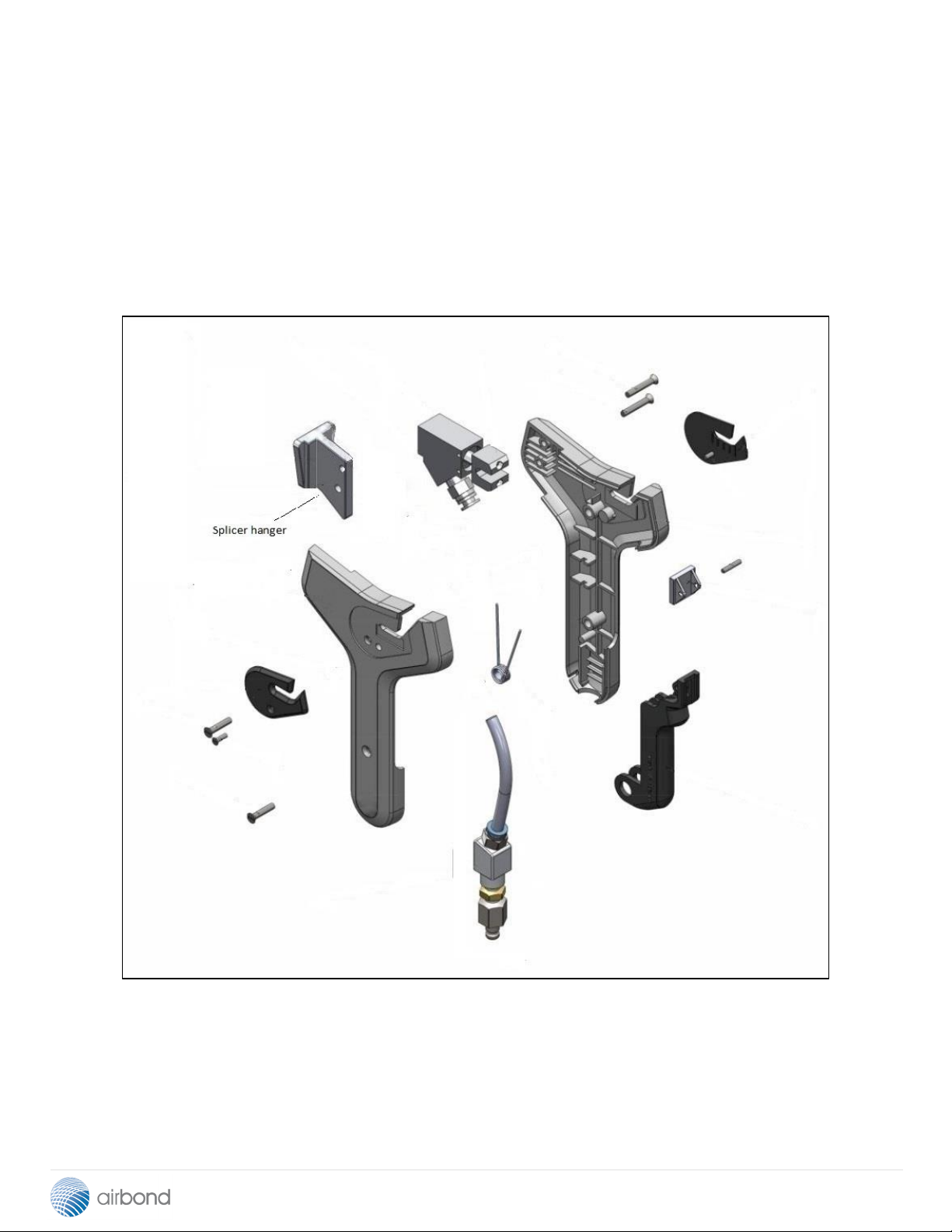
The 701 range has now been improved. It remains lighter than most of our other splicers, and just as
strong, but the original injection-moulded ABS outer shell has been replaced by one printed from
polyamide. The actual splicer body remains protected from wear and tear, safe inside an impact-
resistant PA12 shell. The connector system has been improved, by integrating it into the body,
resulting in enhanced reliability in service.
As with the original, the 701 Series 2 splicers resist damage in service better than most products on
the market; but when they do go wrong, they are easy to maintain. They can be dismantled and
rebuilt in just a few minutes.
The range of application of the 701 Series 2 is just as remarkable as its predecessor. A unique and
patented form of splicing chamber and splicing system is so powerful that a single specification can
handle yarns of widely different counts.
Splice format: Ends opposed.
Applications: Composites processes such as filament winding, pultrusion, and weaving.
Yarns: Carbon fibre, glass fibre, aramid, Panox, synthetic C.F.
Yarn counts: Up to 7000 tex.
Twist: Zero or low twist.
4

701 Series 2: Changes to the specifications
In its original form, the Model 701 Splicer had an injection-moulded ABS body shell. Some fittings
were made of metal, and were held in place by elements of the body shell, and screws. An example
of this construction was the hanger wedge, which fitted into a recess in the body, and was secured by
two screws. The hanger is seen here at upper left.
5

Model 701 Series 2: Changes to the specifications
Here are two examples of how the splicer specification has been improved in the Series 2
This example shows the body of the
701 HW Series 2 splicer.
In the Series 1 splicer, the hanging
wedge was a separate item, machined
from aluminium, which was secured by
screws to the splicer body.
In the Series 2, the wedge –at top
centre –of the HW model is printed
into the splicer outer shell
This example shows the body of the
701 HF Series 2 splicer.
In the Series 1 splicer, air connector was
a separate item, a machined part, which
sat in a recess in the splicer body.
In the Series 2, the connector –at lower
left –is printed into the splicer outer
shell. The small circular housing,
for the flow control unit, can be seen,
also printed as part of the connector
6

Getting started
7

Model 701 –getting started
Please read this section before you start operating the splicer. The rest of the manual deals with
maintenance, and with details of products; those sections will not be needed immediately.
Remove all packaging. For each splicer, you will have the appropriate splicing chamber –which will
usually already be fitted.
Depending on what you have ordered, you may have some or all of the following:
Additional splicing chamber(s)
Optional hanger
Optional hanging clip
Optional flow control device
It may be useful to have a fixed place to store the splicer temporarily when the operator has finished,
in which case you will have specified the “W” modification. This modification will change the splicer
designation –the Model 701 H, for example, becomes the 701 HW. If it has been supplied, bolt the
hanging clip to a convenient spot on a machine. The splicer can then be placed in the hanging clip
when not in use. This reduces the likelihood of the splicer being dropped and damaged in service.
You may have chosen to have a flow control device fitted. In that case, you will have specified the
“F” modification. This modification changes the splicer designation further – the Model 701 H, for
example, becomes the 701 HF, and the Model 701 HW becomes the 701 HFW.
Connect the splicer to an air line.
Under normal circumstances, the line pressure should be around 6 bar. The line should preferably
be fitted with a pressure regulator so that adjustment may be made to suit local needs.
Hold the splicer with the trigger button facing the body, and press the trigger with the thumb.
Look down into the splicer
Press trigger part-way down - see the pad move until it hits the chamber
Press trigger further - listen for the air blast
8

Overlap the yarns by 150
mm, place the splicer at the
centre of the yarns, and
squeeze the trigger to make
the first splice.
Do not apply much tension
to the yarns; if you do, the
splicing efficiency will be
reduced.
Once the first splice is
complete, slide the splicer
sideways by about 40 –50
mm and repeat
The Model 701 has been designed to splice low to heavy-count yarns in materials such as glass and
carbon.
Airbond research has shown that standard splicers –which typically make joints of around 30 mm
in length –produce splices which are weak. Heavy-count yarns demand longer splices, typically
up to 150 mm for 4800 tex.
The Model 701 accomplishes this by making three or more splices in a line; it is this procedure
which is described below. The splice is made in several stages: three intermingling steps,
followed by hand-trimming of the finished joint.
9
Model 701 –Splicer threading

Now make the third.
After the third splice, cut off
the waste ends of yarn using a
scissors.
This technique has proved very
successful with a number of
materials; the picture below
shows splices in glass, carbon
and aramid. It is clear that the
result for carbon is excellent –
the fibre is very easily damaged
by conventional splicing
processes.
The triple-splice structure of
the compound joints is clearly
visible in this photograph.
10

.
Important service information
Apart from accidental damage, the Model 701 requires little attention.
However, cleaning and specific lubrication should NEVER be neglected.
Obviously, there should be frequent examination for signs of fibre build-up in
the inner parts of the splicer. Fibre should be removed.
Most important, the valve which actuates the chamber need NO lubrication.
The only lubrication (white grease) should be placed on the 2 large O-rings
(Item 218). The frequency of lubrication depends upon the nature of the
factory environment and the workload on the splicer.
As a general rule, the pistons should be removed and ONLY the O-rings
greased with Molykote 111 (available from the company) at least once per
quarter. The service interval should be reduced if the splicer experiences very
heavy work loads.
11

Model 701 –General product information
12

Introduction
With the development of high-performance yarns for industrial applications, there is an increasing
need for making splices in yarns of very heavy count - typically glass fibre and carbon fibre rovings of
up to 4800 tex. Counts already exceed 15000 tex.
It made good technical sense for Airbond to design the new heavy-count splicer around the design
features of the successful Model 101. The 101, originally a splicer for carpet yarns, was designed
with durability and simple servicing in mind, and has proved its reliability over many years of service.
The Model 101 was then improved, when the Model 105 was introduced. Even simpler than the
101, the 105 was just as effective.
The result of the further development of the Model 105 was the Model 113 - simple, small and light
like the 105, but capable of splicing neat, strong joints in rovings. The principles of the Model 113 led
to the design of the Model 701 in making the splicer more robust with less maintenance needed. The
701 set a new standard as an effective and user-friendly tool for making extra-large splices in a wide
range of yarns from 10Tex up to these very heavy yarns. After only a short production life, its
performance was such that it has been accepted as a splicer for any count yarn in countries across
the world.
The 701 splices 4800 tex as routine, and in most circumstances it can handle 9600 tex.
Now the Model 701 series 2 splicer is the direct counterpart to the Model 701 –similar in
appearance but 3D printed in tough PA12 polyamide. Being 3d-printed, the Model 701 cases are
made in one piece –the case and internals are combined, producing a lighter but stronger structure.
The Model 701 is currently available in four forms. Further variants are likely to be added to the
range in the near future.
13

General description
The Model 701 Splicer has a number of components mounted inside a case structure in which
airways conduct the compressed air for the splicing action.
Trigger - pressing the trigger initiates the splicing operation.
Valve - operation of the trigger moves the valve allowing compressed air to pass into the body head
for splicing.
Pad - in the initial operation, the operators press of the trigger closes the pad onto the splicing
chamber prior to the splicing action.
Splicing chamber - having a profiled recess on the front face which, with the closed pad, forms a
chamber in which the splice is made. Air enters into the chamber to form the splice.
The Model 701 is simple and easy to maintain. Moreover, its construction is such that it is extremely
rugged, and requires very little attention in service. The splicer has revolutionary and patented
splicing chamber technology, which enables the splicer to make joints in a wide range of yarns
without any change - in general, there is no need to change chambers when changing yarns
14

701 H Standard specification with no accessories
701 HW Splicer with a hanging kit
701 HF Splicer with a flow control
701 HFW Splicer with a hanging kit and flow control
15
701 Model range
Example:
Splicer Model 701 HFW, fitted with wedge hanger and flow
control (flow control is visible on the other side).
Note the QR code; scanning this code will enable the user to
access the Airbond web site - and an on-line version of this
technical manual for the splicer.

701 H
16

The outer surface of the lower shell of
the 701 H Series 2 splicer.
Note:
The rectangular insert at the top of the
shell; in the real splicer this houses the
identification label, complete with QR
code.
The inner surface of the lower shell of
the 701 H Series 2 splicer.
Notes:
There are five locations for the
securing screws –fewer than on the
Series 1 splicers.
The air connector at the base of the
handle is now an integral part of the
splicer shell.
17

The outer surface of the upper shell of
the 701 H Series 2 splicer.
Note:
The five holes for the securing screws.
The inner surface of the upper shell of
the 701 H Series 2 splicer.
18

701 HF
19

The outer surface of the lower shell of
the 701 HF Series 2 splicer.
Note:
The rectangular insert at the top of the
shell; in the real splicer this houses the
identification label, complete with QR
code.
The inner surface of the lower shell of
the 701 HF Series 2 splicer.
Note:
The air connector at the base of the
handle now incorporates a part of the
flow control system (the small hole in
the air connector structure, housing the
flow controller is clearly visible).
20
This manual suits for next models
6
Table of contents