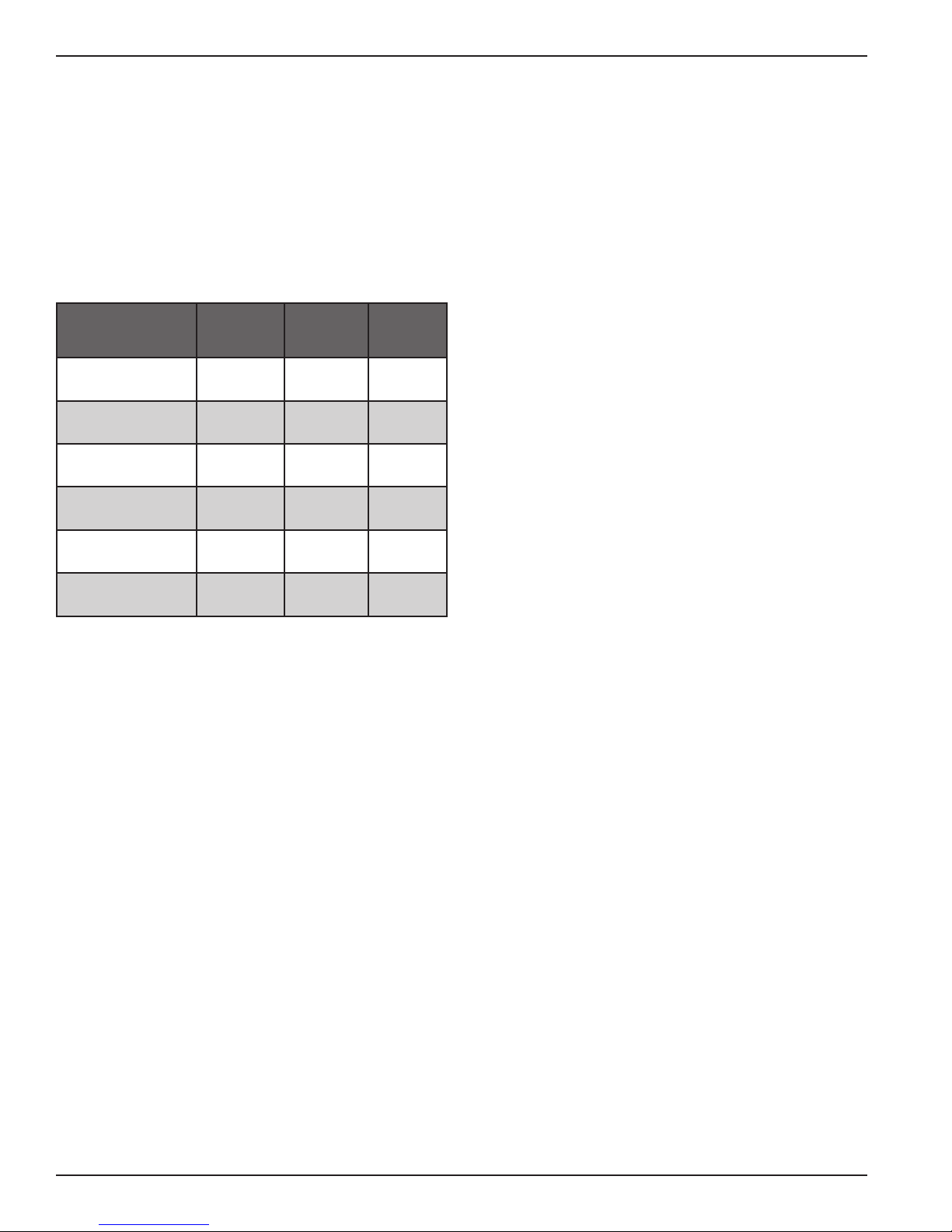
Aircel DHT-20 User manual

Installation
and Operation Manual
Aircel
High Inlet Temperature Refrigerated Air Dryer
Models DHT-20, 40, 50, 75, 100, and 125
Installation,
Operation, and
Service Information
This manual is property of the owner. Leave with the unit when set-up and
start-up are complete. Aircel LLC. reserves the right to change design and
specifications without prior notice.
Throughout this manual,
signal words are present
to advise of safety
precautions and/or
standard practices. Obey these
signal words as defined below:
DANGER! - indicates an
imminently hazardous
situation which, if not
avoided, will result in death
or serious injury.
WARNING! - indicates a
potentially hazardous
situation which, if not
avoided, could result in
death or serious injury.
CAUTION! - indicates a
potentially hazardous
situation which, if not
avoided, may result in
minor or moderate injury.
Notice: - used to address
practices not related to
personal injury.
Illustrations are for reference
only, as actual product may vary.
Patent Number for DHT-50 to 125:
6,691,428

2
WARNING!
General Safety Procedures
• Improperinstallation,operation,serviceormaintenancemaycontributetoconditions
in the work area or facility that could result in personal injury and product or property
damage. Check that all equipment is properly selected and sized for the intended use.
• Consultandcomplywithnationalandlocalcodesrelatingtofireorexplosionandall
other appropriate codes when determining the location and operation of this equipment.
• Safeandefficientoperationoftheunitdependsonproperinstallationandservice.
• Authoritieswithjurisdictionshouldbeconsultedbeforeinstallingtoverifylocalcodesand
installation procedures. In the absence of such codes, install unit according to the National
Electric Code, NFPA No. 70-latest edition.
• Aqualifiedinstallationandserviceagentmustcompleteinstallationandserviceofthis
equipment.
• DONOTweldon/topressurevesselormodifyitinanyway.
• DONOTremove,modify,oradjustprotectiveorsafetydevices.
• Lockoutpowersupplyanddepressurizesystembeforeperformingmaintenanceorservice
work.
• DONOToperatetheequipmentwiththecontrolpaneldooropen.
Notice: For optimum performance, use only original equipment replacement parts.
Notice: For information and notes specific to a custom designed and built dryer, reference the
drawing package provided with the unit.
AircelDHTSeries-Models20-125

HighInletTemperatureRefrigeratedAirDryer
3
Contents
SafetyStatements .................................................. 2
DataSheet............................................................. 3
RefrigeratedDryerSerialPlateLabel .................... 4
RefrigerantSafetyPrecautions .............................. 5
DesignParameters................................................. 6
Description............................................................ 6
System.......................................................... 6
RefrigerationCircuit .................................... 7
Compressed Air Circuit................................ 7
Purpose and Intended Use..................................... 9
Inspection on Arrival ............................................ 9
Lifting Information ............................................. 10
Installation Codes and Procedures ...................... 10
Installation.......................................................... 11
Typical Installation ............................................. 12
PreliminaryStart-UpChecklist............................ 13
AutomaticDrainValveAdjustments................... 14
Operating Procedure ........................................... 14
AirCooledCondenserRequirements .................. 14
Data Sheet
This manual contains specific precautionary statements relative to worker safety.
Readthoroughlyandcomplyasdirected.Discusstheuseandapplicationofthisequipment
with a representative listed on the manual back cover. Instruct all personnel on safe use and
maintenance procedures. Understand and obey the following signal words used in this manual.
•DANGER! - indicates an imminently hazardous situation which, if not avoided, will
result in death or serious injury.
•WARNING! - indicates a potentially hazardous situation which, if not avoided, could result
in death or serious injury.
•CAUTION! - indicates a potentially hazardous situation which, if not avoided, may result in
minor or moderate injury.
•Notice: - used to address practices not related to personal injury.
Shut-DownProcedures........................................ 15
Shut-DownEmergency............................... 15
Short-TermShut-Down.............................. 15
ServiceInformation............................................. 16
Maintenance............................................... 16
Troubleshooting.................................................. 18
Electrical ................................................... 18
Refrigeration .............................................. 18
CondensateRemoval.................................. 19
Other.......................................................... 19
Troubleshooting Table........................................ 20
Appendix ............................................................ 25
RefrigerantMaterialSafetyDataSheet ...... 25
WiringDiagram ......................................... 30
ServiceNotes ...................................................... 33
Warranty............................................................. 36
ModelNumber________________________________ SerialNumber ___________________________________
DateofManufacture ___________________________
ShipDate _____________________________________ InstallationDate _________________________________
Customer Name _________________________________________________________________________________
Address __________________________________________________________________________________
__________________________________________________________________________________
A c c e s s o r i e s ___________________________________________________________________________________________________________________
O t h e r _____________________________________________________________________________________________________________________

4
Refrigerated Dryer Serial Plate Label
ForMfgPersonnel:AffixLabelHereif
DataSheetonpg.3wasnotcompleted.
AircelDHTSeries-Models20-125

HighInletTemperatureRefrigeratedAirDryer
5
Refrigerant Safety Precautions
Refrigerant First Aid Recommendations
Inhalation
If high concentrations are inhaled, immediately
remove individual from affected area to an area
with a fresh air supply. Keep individual calm.
If not breathing, give artificial respiration or if
havingdifficultybreathing,giveoxygenandcallfor
emergency services.
Skin Contact
In case of contact with the skin, immediately flush
skinwithcleanwaterforatleast15minutes.Treat
for frostbite if necessary by gently warming affected
areasandcallforemergencyservices.Removeany
contaminated clothing or shoes.
Eye Contact
In case of contact with the eyes, immediately flush
eye(s)withcleanwaterforatleast15minutesand
call for emergency services.
CAUTION!
Inhalation, Skin, & Eye Irritant
• Usepropersafetyandprotective
equipment, including chemical
safety goggles or face shield and
impervious gloves when handling
refrigerants.
• Exercisecaretoensurethatliquid
refrigerant does not come in contact
with your skin or eyes.
• DONOTSMOKE.
• Ventilationinworkareamustbe
adequate to keep the concentration
of refrigerant below 1,000 ppm.
• Systemmustbefreeofallrefrigerant
before any welding or brazing can be
performed and must be done in a
well ventilated area.
• Decompositionofrefrigerantsis
hazardous! This material can be
decomposed by high temperatures
caused by an open flame.
Hydrofluoricacidandpossibly
carbonyl fluoride can form in a
liquid or gaseous state. Avoid
exposuretothesetoxicfumesand
irritating materials.
• Leavetheworkareaimmediatelyif
youexperienceanyofthefollowing:
smell something unusual, feel light-
headed,experienceshortnessof
breath, feel a tingling sensation in
your fingers or toes, suddenly feel
warm or a rapid heartbeat.

6
Design Parameters
Typeofdryer:Refrigerated
Powersupply:115,230Volt/singlephase/60Hz
Refrigeranttype:R-134A
ChemicalComposition:HFC
Parameter
Description
Optimum Maximum Minimum
Air Pressure
(PSIG) 150-175 200 80
Air Inlet
Temperature (°F) 100-180 200 40
Ambient
Temperature (°F) 75 100 32
SuctionGauge
Reading(psig) 28-40 60 28
DischargeGauge
Reading(psig) 160-250 350 80
Evaporator
Temperature (°F) 38-42 60 33
Description
System
A broad range of non-cycling refrigerated
compressed air dryers from 10 to 10,000 scfm is
offered.TheHighInletTemperatureRefrigerated
AirDryerseriescoversaflowrangefrom20to
125scfmprovidingreliable,constantdewpoint
performance in all flow conditions. Through
optimization of critical dryer components – heat
exchanger,separator,andcondensateremoval–the
system ensures the highest performance at full-
andpartial-loadconditions.R-134arefrigerant
is used in all refrigerated compressed air dryers
asstandard.R-134aistheindustry’spreferred
choice because of its 0.0 ozone depletion factor and
globalwarmingpotential.R-134aisaone-blend
refrigerant providing consistent performance (no
temperatureglide)andeasyservice(nomixtureof
different refrigerants).
Hotsaturatedairenterstheair-to-airheat
exchangeroftheHighInletTemperature
RefrigeratedAirDryerandisprecooledbythe
outgoing dry air. Precooling saves energy by
reducingtheheatloadonthedryer’scompressor.
The cool saturated air enters the air-to-refrigerant
heatexchangerwhereairtemperatureislowered
tothe48to50°Frange.Thisdramatictemperature
drop condenses water and oil.
Themixtureofcoldairandcondensationthen
flows into the two-stage separator filter where
liquids and contaminants are removed by
centrifugal action, directional flow change, and
velocity reduction. Once bulk liquids have been
removed, the compressed air goes through a
stainless steel mist eliminating filter that coalesces
oilaerosolsandoilvaporswithinthe50-micron
range, and then separates and removes them. At
this point, the compressed air is dry and virtually
oil-free.
Cold,dryairexitsthroughtheprecoolerheat
exchangerandisreheatedbyincominghotair.
Reheatingrestoresenergyandalsoprevents
condensation from forming on the outside of air
distribution piping. In the refrigeration unit, the
compressor pumps hot, high-pressure gaseous
refrigerant to the condenser where it is cooled
and liquefied by ambient air. From the condenser,
liquid refrigerant first flows through the receiver,
then through a filter/dryer, and finally through the
expansionvalvewherepressureandtemperature
are reduced. This reduction in pressure causes
the liquid refrigerant to boil until it reaches the
saturation temperature that corresponds to its
pressure. As the low-pressure refrigerant passes
through the evaporator, heat flows from the
compressed air to the refrigerant, causing the
boiling to continue until all refrigerant is vaporized.
Refrigerantgasisreturnedtothecompressorand
the cycle is repeated. A hot gas by-pass valve is used
to control temperature in the evaporator.
AircelDHTSeries-Models20-125

HighInletTemperatureRefrigeratedAirDryer
7
Refrigeration Circuit
Refrigerantiscycledthroughaclosedloop
system commonly known as high pressure and
lowpressure.Refrigerantiscompressedbythe
compressor to a gas with high temperature and
high pressure, which then travels to the condenser
(air/water cooled) to drop the temperature and
change from gas to liquid. Liquid travels through
to the evaporator (refrigerant-to-air part of the heat
exchanger)andbacktothecompressorsuctionside
andtheprocessrepeatsitself.Athermalexpansion
hot gas by-pass valve is used on the non-cycling
dryers from the high side to low side as a freeze
protectorinlowloadconditions(125scfm).
Compressed Air Circuit
The compressed air dryer circuit uses a patented
air-to-airheatexchanger,whichactsasaprecooler/
reheater(40scfmratedmodelandhigher).Hot,
saturated, compressed air first enters the air-to-air
heatexchanger,whereitispre-cooledbyoutgoing
airfromtheair-to-refrigerantheatexchanger.
Thisenergysavingheatexchangerprovides
several advantages, such as a reduction of the heat
load imposed on the refrigerant compressor and
condenser, providing more energy to the outlet air,
and preventing condensation of moisture on the
outside of the plant distribution air line piping.
Fromtheair-to-airheatexchanger,airwillenter
into the evaporator further reducing its temperature
to a desired pressure dew point. As the air is
cooled, moisture will be condensed, where it is then
separated and discharged through the condensate
drain. The cooled air then reenters the air-to-air
heatexchanger,inadirectionoppositetotheflow
of the warm, saturated incoming air. This counter
flow action assures high temperature differential
throughouttheheatexchanger,resultinginamore
effective heat transfer.
compressor liquid
receiver
air out
air in
refrigerant
inlet
refrigerant
outlet
air cooled
condensor
suction
accumulator
Air to Refrigerant Heat Exchanger
Refrigerant Circuit
TypicalSchematicFlowDiagram(20scfmratedmodels)

8
air inlet air outlet
separation cell
air to refrigerant
heat exchanger
refrigerant
inlet
air
refrigerant refrigerant outlet
exiting air
incoming air
stainless steel mist eliminator
pre-cooler / heater
TypicalSchematicFlowDiagram(40-125scfmratedmodels)
AircelDHTSeries-Models20-125

HighInletTemperatureRefrigeratedAirDryer
9
Purpose and Intended Use
Highinlettemperaturerefrigeratedairdryersare
designed for the purpose of removing moisture
from the compressed air by using mechanical
refrigeration and providing dew points as low as
(48°F-50°F).Thesedryersareusedtoprotect
industrial compressed air systems, machinery, and
tools. They are designed to deliver the required
dew point at specified inlet air temperature, inlet
air pressure, inlet flow and ambient temperature
conditions.Toensuremaximumperformanceand
safe operation of this dryer, everyone associated
with its installation, operation, and maintenance
must read and carefully follow the instructions of
this manual.
CAUTION!
• Misuseormodificationofthis
equipment may result in personal
injury.
• Donotmisuseormodify.
Inspection on Arrival
All high inlet temperature series dryers are tested
andoperatedbeforeshipment.However,shipping
vibration may cause damage such as loosening of
certain parts. To ensure smooth installation, it is
recommended that immediately upon receipt of the
unit, the system is checked for the following:
1. Inspect unit on delivery.
2. Reportanydamagetothedeliverycarrier.
3. Requestawritteninspectionreportfromthe
Claims Inspector to substantiate the claim.
4. File claims with the delivery carrier.
5. Compareunitreceivedwithdescriptionof
product ordered. Check the data label and
makesurethatitisthecorrectModelthatyou
had ordered. Note the equipment Capacity and
PowerSupplyrequirementsandensurethatthey
are in accordance with your specifications. The
rated conditions of the dryer are indicated on
the serial plate label. If there is any discrepancy,
contact your representative listed on the manual
back cover.
6. Vibrationduringshippingcanloosenthe
connections.Soinspectallpipeandtubingand
make sure they are all tightened and secured.
7. Observe pressure of refrigerant analyzer gauge
(suction) to determine if refrigerant has leaked
out during transit. If the gauge reading does not
match that mentioned on the serial plate label,
immediatelycontactTechnicalSupportlistedon
the manual back cover.
8. Reportincompleteshipmentstothedelivery
carrier and your service representative.

10
Lifting Information
1. Useallliftingpointsprovided.Specialcaremust
be used when lifting the dryer to prevent tip-
over.
2. Use clevis connectors, not hooks, on lifting
slings.
3. Only lift unit under support frame/base by using
theforkliftopeningsprovided.Donotliftby
piping.
4. Checktheapproximateweightprovidedon
the specification control drawing to ensure
adequate lift truck capacity.
5. Allowonlyqualifiedoperatorstoliftthe
equipment.
6. RefertoapplicableOSHAregulationsandlocal
codes when using cranes, forklifts, and other
lifting equipment.
WARNING!
• Failuretolifttheunitcorrectlycan
result in severe personal injury or
property damage.
• Useappropriateliftingequipment
and adopt all safety precautions
needed for moving and handling the
equipment.
• Ahandcart,forkliftorcraneis
recommended for unloading and
installation.
• Liftunitbyliftinglugsandframe
only.Donotliftbypiping.
Installation Codes and Procedures
WARNING!
• Followproperlockout/tagout
procedures before performing
service or maintenance work.
• Electricalinstallationmustbe
performed by a qualified electrician
and comply with all applicable
national and local codes.
1. Safeandefficientoperationoftheunitdepends
on proper installation.
2. Authorities with jurisdiction should be
consulted before installing to verify local codes
and installation procedures. In the absence
of such codes, install unit according to the
National Electric Code and NFPA No. 70-latest
edition.
3. A qualified installation and service agent
versed in all regulatory codes must complete
installation of this unit.
CAUTION!
• AcopyoftheOperationManual
must be made available to all
personnel involved with the
installation, operation and
maintenance of the equipment,
to avoid injury to personnel or
property damage.
• Appropriatetoolsmustbeusedfor
all installation and maintenance
work, to avoid injury to personnel
or property damage.
AircelDHTSeries-Models20-125

HighInletTemperatureRefrigeratedAirDryer
11
Installation
1. Locateunitonalevelfoundation.Dryershould
be mounted on a suitably structured flat and
level floor or base that is free from vibration.
2. Install unit to provide adequate clearance for
maintenanceservices.Dryerandaccompanying
filters (optional) should be installed with at least
2to5feetclearancefromtheadjoiningwallsto
provide easy access for routine maintenance and
adequate air flow across the condensing coil.
3. The frame or cabinet must be securely bolted
to the foundation to prevent movement
resulting from earth tremors and induced piping
vibration.
4. Install unit using the correct pipe size and
pressurerating.SeeRatingandSpecification
information section. Connect the inlet of the
dryer to the moist gas from the compressor/
receiver/inlet filter. Install the Inlet piping and
the inlet shutoff valve. Install the outlet piping
and the outlet shutoff valve (a union with a
valve by-pass can be installed at the inlet and
outlet valves to accommodate isolation of the
dryer for maintenance). Compressed air piping
has to be at least the same size as that of the
inlet and outlet connections of the dryer. Larger
pipe sizes can be used with appropriately rated
reducers.
Operation at elevated pressure or temperature
may cause damage to the dryer or serious injury
to personnel. Each dryer is checked at the
factory for proper operation at the conditions
noted on the serial plate label.
5. Provideadequatepowersupply.SeeRating
andSpecificationinformationsection.Makeall
electrical connections to the dryer as shown on
thewiringdiagram.Specialcaremustbetaken
in connecting the proper voltage as indicated
on the specification sheet and wiring schematic.
It is mandatory that the dryer be grounded.
Useofyourplant’sframeasagroundmay
cause problems with the controls. A fused
disconnect is not supplied with this equipment;
therefore, one must be supplied by customer.
All electrical fuses, breakers, etc. should be
sized by a qualified electrician and comply with
all applicable national and local codes. Our
company is not liable for any code violations,
component damage, downtime or consequential
damage related to customer supplied electrical
components and connections.
6. The ambient temperature should be between 40
°F and 100 °F. Low temperature could affect
the dryer process and result in high outlet dew
point. In conditions where the ambient drops
below freezing, it is recommended that a heat
trace be used for the equipment. This will
ensure trouble-free operation during the winter
months (the dew point of the outlet air will be
consistent).
7. Donotplacethesysteminserviceuntilthe
above steps have been completed and that all
ratings and specifications have been verified to
match the requirements in this manual.
8. If there are any changes in the operating
conditions of the system from those listed
inRatingandSpecificationsection,contact
TechnicalSupportforadviceonnecessary
adjustments.

12
Typical Installation
AircelDHTSeries-Models20-125
Typical Installation

HighInletTemperatureRefrigeratedAirDryer
13
Preliminary Start-Up Checklist
Notice: For all models, wait at least 6 hours
after transporting or moving of dryer system
before starting the dryers. Turn the main power
switch to the dryer on, but do not turn
the dryer on/off switch to the on
position until 6 hours have passed. The
power indicating light will be on.
1. Check that the inlet and outlet connections
are the correct size and pressure rating, and
tightened securely.
2. Check that the correct power supply is
connected to the high inlet temperature series
refrigerated air dryer system with an adequate
disconnect switch.
3. Check that all compressed air line service valves
are open and that compressed air is available to
be supplied to the high inlet temperature series
refrigerated air dryer system.
4. Check that all liquid drain service valves are
open. This is to ensure that any residual bulk
condensate that may have accumulated in the
compressed air lines is discharged immediately
upon start up. These drains must be closed
once system is brought on line for use. The
drain valve on the refrigerated air dryer can be
opened by pushing the test button located on
the front control panel.
5. Withthecustomer-suppliedcompressedair
to the system, OPEN the inlet valve slowly to
graduallypressurizethesystem.Donotopen
valve too quickly. Opening valve and suddenly
pressurizing the system can cause damage to the
dryerheatexchangerandothercomponents.
6. Check the complete air system piping
connections and dryer system connections for
leaksatthistime.Repairandretestallleaks.
7. Verifythatallinstrumentation(pressure
gauge/s) and drain air tubing fittings are tight.
8. Ensure that the air system has come up to
full pressure and has filled the high inlet
temperature series refrigerated air dryer with
compressed air. Before opening the outlet valve
on the system and after the dryer has been
started under no load, let the dryer run for at
leastfifteen(15)minutestoallowstabilization
ofthesystem.Verifythefollowing:
a. The dryer is designed to run continually
and should not be cycling on and off with
the air compressor. The non-cycling
operation of the dryer is controlled by an
automaticexpansionvalveorathermostatic
expansionvalve/hotgasby-passvalve.The
valves will open and close automatically
depending on the amount of heat load to the
evaporator, thus maintaining the desired
pressure dew point.
b. Check the inlet compressed air temperature
and pressure to the dryer and verify that it
meets the specified requirements.
c. Fan rotation, for dryers with an air-cooled
condenser, rotation should be in accordance
with the fan rotation shown on the details
located on top and back of the condenser.
Cooling air is drawn through the condenser
coils. If the motor rotation is not correct,
turn off the power switch and put the main
power supply disconnect in the “off”
position; lock and tag; check the wiring;
correct the wire lead locations; recheck for
correct rotation (3 phase unit only).
d. The refrigeration gauge readings should be as
follows:
• RefrigerantsuctionpressureR-134a
= 28-40 psig
• RefrigerantdischargepressureR-
134a=160-250psig
Notice: The above discharge pressures depend
upon ambient temperature and can
vary slightly according to temperature
fluctuations.
9. After all of the preliminary start up checklist

14
has been completed, the compressed air outlet
valve on the high inlet temperature refrigerated
air dryer system can now be slowly opened to
supply clean dry compressed air to the facility.
10.Afterstart-upandapproximatelyonemonth
of service, check that all piping and fittings are
tight and free of leaks.
Notices:
• Modelswiththehotgasby-passvalvesand
expansionvalvesarepresetatthefactory
forthedesireddewpoint.Donotadjust
without consulting with the factory.
• Thedryersarefullyautomaticanddonot
requireanyauxiliarycontrols.
Automatic Drain Valve Adjustments
The automatic drain valve supplied is standard
on the separator and should open regularly and
discharge any accumulated water into the drain
line. The period between openings varies with the
dryer and operating conditions (electronic type). To
minimize air losses, the timer should be adjusted
to open the drain solenoid just long enough to
dischargetheaccumulatedcondensate.Setthe
timer so that only air discharges at the end of the
openperiod.Recommendedinitialsettingsare(7)
seconds drain opening (on time) and a (7) minute
close time (off time). If air discharges far more than
(2) seconds from the separator discharge, set the
timer for a longer cycle time. If liquid discharges as
the solenoid is closing, set the timer for a shorter
cycle or a longer open time.
Operating Procedure
After the initial startup, the dryer operation is
completely automatic. To understand the details of
the operation, use the flow diagram on pages 7-8
and the timing sequence of the dryer.
Air Cooled Condenser Requirements
Cooling air must be drawn from a clean source to
reduce dust and dirt accumulation on the condenser
coils.Airtemperatureshouldnotexceed100°F
(38°C).
Model by
SCFM Rating
Refrigeration
Hp
Cooling air
flow (cfm)
20 1/3 350
40 1/2 500
50 1/2 500
75 3/4 900
100 3/4 900
125 11125
AircelDHTSeries-Models20-125

HighInletTemperatureRefrigeratedAirDryer
15
WARNING!
• Toavoidpossiblehazardorinjury,
the operator should be fully familiar
with the high inlet temperature
series refrigerated air dryer system
and its operation.
• Whenthesystemisshutdownand
power removed, lock out power
supply and depressurize system
before performing maintenance
or service work to avoid injury to
personnel or property damage.
Shut-Down Procedures
Shut-Down Emergency
The high inlet temperature series refrigerated
air dryer system can be shut down under any
conditions and at any time by turning the unit off
at the dryer or at the main disconnect switch. Once
power is removed from the dryer system, the dryer
must be isolated from the compressed air stream to
avoid a refrigeration circuit over pressure situation.
Short-Term Shut-Down (over night or weekends)
The high inlet temperature series refrigerated air
dryer system can be shut down at any time by
turning the unit off at the dryer by using the on/off
switch or at the main disconnect switch.

16
Service Information
To reach a field service technician or for technical
support, please call the number listed on the
manual back cover.
Maintenance
Refrigeratedairdryersrequireverylittle
maintenanceforsatisfactoryoperation.Good
performancecanbeexpectedifthefollowing
routine maintenance steps are taken.
WARNING!
• Beforeanyserviceormaintenance
work is performed on the high inlet
temperature series refrigerated air
dryer system, disconnect power
supply and lock out power supply
and depressurize system before
performing maintenance or service
work.
• Followproperlockout/tagout
procedures before performing
service or maintenance work.
• Priortoperformingany
maintenance on the dryer, all
personnel are strongly advised to
familiarize themselves with the
equipment by reading the entire
contents of this operation manual.
All safety procedures should be
followed prior to performing any
maintenance activity on the dryer.
Daily
With the dryer on-line:
• Verifytheoperatingpressure,temperature,and
flow rate are correct and conform to those listed
intheRatingandSpecificationInformation
section. Adjust system if required.
• Alwayscheckrefrigerantgaugestoinsure
refrigeration system is working properly.
• Checkcondensatedrainseparatorforproper
condensate discharge. If no discharge is evident
then depressurize the unit, dismantle and clean
separator and/or drain line. Proper drain trap
maintenanceistheowner’sresponsibility.Itis
not covered by warranty.
• Makecertainairflowisdirectedthroughdryer
only. Observe by-pass valves proper positions.
Weekly
• Repeatalldailyinspectionsandrecorddatain
Maintenancelog.
• Cleanthecondensercoilsofaccumulated
dust and dirt with a soft brush and/or with
air pressure from a compressed air nozzle
(maximum100psig).
• Checkthegaugereadingsforgoodsystem
operation.
• Checkoilremovalfilter(coalescer)indicator(if
applicable); if it is red, replace the filter.
AircelDHTSeries-Models20-125

HighInletTemperatureRefrigeratedAirDryer
17
Filter Element Replacement
1. Depressurizetheairsystemtorelease
the compressed air from the air dryer.
Notice:Shuttingdowntheaircompressorwill
not depressurize the air dryer unit.
Close air line valves before and after
dryer and then depressurize unit.
Depressurizedryerbypushingthetest
button on the dryer system drain until
there is no more pressure in the dryer
system.
2. Removethefilterbowlbyturningthebowl
1/4 turn counter clockwise, be sure the O-ring
is in place on the top half of the oil filter
housing and that the O-ring seats properly. Air
leaks may occur if the O-ring is not secured
(important).
3. The same procedure applies when removing
the filter separator for changing the element (if
applicable).
Hot Gas By-Pass Adjustment
Check the refrigerant suction pressure gauge for
operation, if it requires adjustments perform the
following steps:
1. Donotturnoffthedryer.Adjustonlywhenno
air is passing through dryer.
2. Open the top cover to reach the valve.
3. If the refrigerant suction pressure is below
30psig(R-134a),turntheadjustmentbolt
clockwise (1/8 turn intervals) and allow a few
minutes for refrigerant to stabilize.
4. Ifsuctionpressureisabove45psig(R-134a),
turn the adjusting bolt counter-clockwise.
5. Letthedryeroperateforafewminutesand
read the suction pressure gauge. Continue to
adjust the valve until the pressure reads between
30-40psig(R-134a).
HotGasBy-passadjustment

18
Troubleshooting
WARNING!
• Beforeanyserviceormaintenance
work is performed on the high inlet
temperature series refrigerated air
dryer system, disconnect power
supply and lock out power supply
and depressurize system before
performing maintenance or service
work.
• Followproperlockout/tagout
procedures before performing
service or maintenance work.
• Priortoperformingany
maintenance on the dryer, all
personnel are strongly advised to
familiarize themselves with the
equipment by reading the entire
contents of this operation manual.
All safety procedures should be
followed prior to performing any
maintenance activity on the dryer.
If there is a problem with the high inlet temperature
series refrigerated air dryer or contamination
downstream is present, the problem may be
identified from one or more of the following
sources:
• Electrical
• Refrigeration
• Condensateremoval(drains)
• Other
Electrical
• Makecertainthatthedryerisconnected
to proper power supply in accordance with
electrical diagram provided.
• Checkelectricalbreaker/fusedisconnectto
determine if there is electrical power to the unit.
• Aquickcheckshoulddetermineifthepower
switch is turned on and the unit is running.
• Afterdeterminingthatthepowerissuppliedto
theunit,gotothenextstep.
WARNING!
• Followproperlockout/tagout
procedures before performing
service or maintenance work.
• Electricalinstallationmustbe
performed by a qualified electrician
and comply with all applicable
national and local codes.
Refrigeration
Notice: Always observe refrigerant analyzer
gauge(s) to determine if and how
refrigeration circuit is operating.
Highinlettemperatureseriesrefrigeratedair
dryerswithR-134arefrigerantshouldread28-40
psig refrigerant suction pressures while unit is
running with low or no load. If the refrigerant
gauge(s) reads more or less than the above specified
pressures troubleshoot the following:
1. Highrefrigerantreadingsgenerallyindicate:
• Dirtycondenser-Cleanimmediately!
• Dryernotturnedonduringairusage.
• Overloading-Airflowmorethandryer
designed for.
• Ifhighambienttemperature-Provide
adequate ventilation for proper cooling.
• Condenserfan(s)notrunning-Call
TechnicalService.
• Refrigerantcontroltoohigh-Adjusthot
AircelDHTSeries-Models20-125

HighInletTemperatureRefrigeratedAirDryer
19
gasby-passvalve(orconstantexpansion
valve) to lower refrigerant pressure to
required settings.
2. Low refrigerant readings generally indicate:
• Lowambienttemperature-Provideambient
temperaturesabove15°F.
• Refrigerantcontrolsettingtoolow-Adjust
hotgasby-passvalve(orconstantexpansion
valve) to raise refrigerant pressure to
required settings.
• Lossofrefrigerant-CallTechnicalService
or a qualified refrigeration service.
Condensate Removal
The high inlet temperature refrigerated air dryer
uses a refrigeration circuit to cool the compressed
air thus condensing the moisture. The moisture is
separated from the dry air and purged out through
an automatic drain.
1. Condensate downstream of dryer:
• Iftheunitisequippedwithautomaticdrain
override switch, push manual override
button to test drain flow.
• Ensureautomaticelectronictimer(if
applicable) is functioning properly.
• Ensuremoistureseparator(and
coalescer) drain lines are free from blockage.
• Iftheunitisequippedwithy-strainer,
disassemble and clean.
• Ifoilisdownstreamfromthedryer:
- Oil coalescer element is saturated.
-Dryernotturnedonduringairusage.
WARNING!
Before any service or maintenance
work is performed on the high inlet
temperature series refrigerated air dryer
system, disconnect power supply and
lock out power supply and depressurize
system before performing maintenance
or service work.
Other
Sometimesawateroroilproblemdownstream
from the dryer can be identified by an inadvertent
action or inaction by the operator.
• Dryernotturnedonbeforeairusage.
• By-passvalvesinwrongposition.
• Airusageexceedingdryercapacity.
• Oilcoalescerelementnotchangedas
needed.
• Automaticdrainsnotmaintained.

20
Problem Probable Cause Remedy
Water downstream
of dryer system or no
discharge from separator/
filter.
Failed or short circuited timer
on drain.
Replacetimerdrain.
Failed drain solenoid. Replacetimerdrain.
Bulk liquid entering the
dryer from upstream.
Check drains on after cooler or air compressor.
Inlet compressed air
temperature to dryer too
high for proper cooling of
compressed air.
Check inlet air temperature and adjust to meet
specifications of dryer system.
InletcompressedairCFM
flow rate too high for dryer
specifications.
Check in inlet air cfm flow rate and adjust to
meet specifications of dryer system.
Leak in the air to air
sideoftheheatexchanger.
Replaceheatexchanger.
Water downstream and
dryer system not working
properly or not working.
Refrigerationcompressor
stopped due to plugged or
dirty condenser coil.
Clean condensing coil and ensure adequate
ventilation of unit.
Refrigerationcompressorshort
cycles and cannot maintain
suction pressure.
Locate leak in refrigeration circuit, repair and
recharge according to specifications.
Low refrigerant. Check for leak in refrigeration circuit, repair and
recharge according to specifications.
Low refrigerant, possible
leak in air to refrigerant
sideofheatexchanger.
Repairorreplaceheatexchangerandrecharge
according to specifications.
Refrigerationcompressor
is overheated.
Turn off dryer and wait 20 - 40 minutes, restart
dryer.
Refrigerationcompressor
has burned out or
windings have gone
to ground.
Replacecompressor,checkforleakin
refrigeration circuit, repair and recharge
according to specifications.
Troubleshooting Table
AircelDHTSeries-Models20-125
This manual suits for next models
5
Table of contents
Other Aircel Dryer manuals