Aircel VF Series User manual

VF Series | Non-Cycling | 10 - 2,000 scfm
DHT Series | High Inlet Temperature | 20 - 125 scfm
AES Series | Energy Saving Digital Scroll | 600 - 10,000 scfm
REFRIGERATED DRYER USER MANUAL
The information in this manual is current as of its publication date and applies to VF, DHT, and AES Series refrigerated air dryers until next revision of this manual.
Copyright © December 2017 Aircel, LLC. All rights reserved.
WARRANTY NOTICE
Failure to follow the instructions
and procedures in this manual, or
misuse of this equipment, will void its
warranty.
WARNING!
Users are required to read the entire
User Manual before handling or using
the product. Keep the User Manual in
a safe place for future reference.

| VF, DHT, AES Series Manual
Refrigerated Air Dryer User Manual
ii
DRYER DATA SHEET
Model Number: Serial Number:
Date of Manufacture:
Ship Date: Installation Date:
Customer Address:
Customer City: State/Zip:
Other:

VF, DHT, AES Series Manual |
Refrigerated Air Dryer User Manual iii
TABLE OF CONTENTS
Section 1: Safety 1
1.1 Introduction 1
1.2 Safety Signal Words 1
1.3 General Safety Procedures 1
1.4 Refrigerant Safety Precautions 1
1.4.1 Inhalation, Skin, & Eye Irritant 1
1.4.2 Refrigerant First Aid Recommendations 2
1.5 Implementation of lockout/tagout 2
1.5.1 Procedures 2
1.5.2 General Security 3
Section 2: Description 4
2.1 Introduction 4
2.2 System 4
2.3 Refrigeration Circuit 4
2.3.1 Types of Refrigerant Used 4
2.4 Compressed Air Circuit 4
2.5 Digital Scroll Compressor 6
Section 3: Installation 7
3.1 Inspection on Arrival 7
3.2 Lifting Information 7
3.3 Installation Codes and Procedures 8
3.4 Locating and Installing the Dryer 8
3.4.1 Air-Cooled Condenser Requirements 9
3.4.2 Cooling Water Requirements 9
3.5 Preliminary Start-Up Checklist 12
3.6 Automatic Drain Valve Adjustments 13
3.7 Zero Loss Condensate Drain 13
Section 4: Operation 14
4.1 Operating Procedures 14
4.2 Short-Term Shut Down 14
4.3 Shut Down Emergency 14
Section 5: Controllers (AES Series) 15
5.1 Home Screen 15
5.2 Status Screen 16
5.3 Information Screen 16
5.4 Alarm Screen 17
5.5 Alarm Log Screen 17
5.6 Diagnostics Screen 18
5.7 Alarm Banner Screen 18
Section 6: Maintenance 19
6.1 Introduction 19
6.2 Maintenance 19
6.2.1 Daily 19
6.2.2 Weekly 19
6.3 Filter Element Replacement 20
Section 7: Troubleshooting 21
7.1 Introduction 21
7.2 Electrical 22
7.3 Refrigeration 22
7.4 Condensate Removal 23
7.5 Other 24
7.6 VF & DHT Series Troubleshooting Guide 25
7.7 AES Series Troubleshooting Guide 30
7.8 AES Series Performance Alert Codes 35
Appendix A: Specifications 36
A.1 Table of Specifications - VF Series 36
A.2 Table of Specifications - DHT Series 37
A.3 Table of Specifications - AES Series 38
Appendix B: Wiring Diagrams 39
B.1 VF Series 39
B.2 DHT Series 42
B.3 AES Series - Air-Cooled Models 45
B.4 AES Series - Water-Cooled Models 52
Appendix C: Material Safety Data Sheets 59
C.1 R-134a 59
C.2 R-404a 66
Service Notes 74
Warranty Information 79


VF, DHT, AES Series Manual |
Refrigerated Air Dryer User Manual 1
1.1 Introduction
To ensure maximum performance and safe operation of an
Aircel refrigerated dryer covered by this manual, everyone
involved with the dryer’s installation, operation, and
maintenance must read and carefully follow the instructions
in this manual.
1.2 Safety Signal Words
Throughout this manual, signal words are present to advise
of safety precautions and/or standard practices. Obey these
signal words as dened below:
DANGER! - Indicates an imminently hazardous situation
which, if not avoided, will result in death or serious injury.
WARNING! - Indicates a potentially hazardous situation
which, if not avoided, could result in death or serious injury.
CAUTION! - Indicates a potentially hazardous situation
which, if not avoided, may result in minor or moderate
injury.
NOTICE - used to address practices not related to personal
injury.
1.3 General Safety Procedures
• Improper installation, operation, or maintenance may
contribute to conditions in the work area or facility that
could result in personal injury and product or property
damage. Check that all equipment is properly selected
and sized for the intended use.
• Consult and comply with national and local codes
relating to fire or explosion and all other appropriate
codes when determining the location and operation of
this equipment.
• Safe and efficient operation of the unit depends on
proper installation.
• Authorities with jurisdiction should be consulted
before installing to verify local codes and installation
procedures. In the absence of such codes, install unit
according to the National Electric Code, NFPA No.
70-latest edition.
• A qualified installation and service agent must complete
installation and service of this equipment.
• DO NOT weld on / to pressure vessel or modify it in any
way.
• DO NOT remove, modify, or adjust protective or safety
devices.
• Lock out power supply and depressurize system before
performing maintenance or service work.
• DO NOT operate the equipment with the control panel
door open.
1.4 Refrigerant Safety Precautions
1.4.1 INHALATION, SKIN, & EYE IRRITANT:
• Use proper safety and protective equipment, including
chemical safety goggles or face shield and impervious
gloves when handling refrigerants.
• Exercise care to ensure that liquid refrigerant does not
come in contact with your skin or eyes.
• DO NOT SMOKE.
• Ventilation in work area must be adequate to keep the
concentration of refrigerant below 1,000 ppm.
SECTION 1: SAFETY
CAUTION!
Misuse / modication hazard
Misuse or modication of this equipment may result
in personal injury.
Do not misuse or modify this equipment under any
conditions.
NOTICE
For optimum performance, use only Aircel replacement
parts.

| VF, DHT, AES Series Manual
Refrigerated Air Dryer User Manual
2
• System must be free of all refrigerant before any welding
or brazing can be performed and must be done in a well
ventilated area.
• Decomposition of refrigerants is hazardous! This material
can be decomposed by high temperatures caused by
an open flame. Hydrofluoric acid and possibly carbonyl
fluoride can form in a liquid or gaseous state. Avoid
exposure to these toxic fumes and irritating materials.
• Leave the work area immediately if you experience any of
the following: smell something unusual, feel light-headed,
experience shortness of breath, feel a tingling sensation
in your fingers or toes, suddenly feel warm or a rapid
heartbeat.
1.4.2 REFRIGERANT FIRST AID RECOMMENDATIONS
1.4.2.1 INHALATION
If high concentrations are inhaled, immediately remove
individual from aected area to an area with a fresh air supply.
Keep individual calm. If not breathing, give articial respiration
or if having diculty breathing, give oxygen and call for
emergency services.
1.4.2.2 SKIN CONTACT
In case of contact with the skin, immediately flush skin with clean
water for at least 15 minutes. Treat for frostbite if necessary by
gently warming affected areas and call for emergency services.
Remove any contaminated clothing or shoes.
1.4.2.3 EYE CONTACT
In case of contact with the eyes, immediately flush eye(s) with
clean water for at least 15 minutes and call for emergency
services.
1.5 Implementation of lockout/tagout
The energy control procedure denes actions necessary to
lockout a power source of any machine to be repaired, serviced,
or set-up, where unexpected motion, or an electrical or other
energy source, would cause personal injury or equipment
damage. The power source on any machine shall be locked
out by each employee doing the work except when motion is
necessary during setup, adjustment, or troubleshooting.
1.5.1 PROCEDURES
The established procedures for the application of energy control
shall cover the following elements and actions and shall be
initiated only be Authorized Persons and done in the following
sequence:
1. Review the equipment or machine to be locked and tagged
out.
2. Alert operator and supervisor of which machine is to be
worked on, and that power and utilities will be turned o.
3. Check to make certain no one is operating the machine
before turning power o.
4. Turn o the equipment using normal shut-down procedure.
5. Disconnect the energy sources:
a. Air and hydraulic lines should be bled, drained, and
cleaned out. There should be no pressure in these lines
or in the reservoir tanks. Lockout or tag lines or valves.
b. Any mechanism under tension or pressure, such as
springs, should be released and locked out or tagged.
c. Block any load or machine part prior to working under it.
d. Electrical circuits should be checked with calibrated
electrical testing equipment and stored energy and
electrical capacitors should be safely discharged.
6. Lockout and/or tag out each energy source using the
proper energy isolating devices and tags. Place lockout
hasp and padlock or tag at the point of power disconnect
where lockout is requried by each person performing work.
Each person shall be provided with their own padlock and
have possession of the only key. If more than one person is
working on a machine, each person shall ax personal lock
and tag using a multi-lock device.
7. Taglock devices shall be used only when power sources
are not capable of being locked out by use of padlocks and

VF, DHT, AES Series Manual |
Refrigerated Air Dryer User Manual 3
lockout hasp devices. The name of the person axing the
tag to power source must be on tag along with date tag was
placed on power source.
8. Release stored energy and bring the equipment to a “zero
mechanical state.”
9. Verify isolation: Before work is started, test equipment to
ensure power is disconnected.
1.5.2 GENERAL SECURITY
1. The lock shall be removed by the Authorized Person who
put the lock on the energy-isolating device. No one other
than the person/persons placing padlocks and lock out
hasps on power shall remove padlock and lockout hasps
and restore power. However, when the authorized person
who applied the lock is unavailable to remove it, her or his
Supervisor may remove padlock(s) and lock out hasp(s) and
restore power only if it is rst:
a. veried that no person will be exposed to danger..
b. veried that the Authorized Person who applied the
device is not in the facility.
c. noted that all reasonable eorts to contact the Authorized
Person have been made to inform her or him that the
lock out or tag out device has been removed.
d. ensured that the Authorized Person is notied of lock
removal before returning to work.
2. Tag out system - Tags are warning devices axed at points
of power disconnect and are not to be removed by anyone
other than the person placing tag on power lockout. Tags
shall never be by-passed, ignored, or otherwise defeated.

| VF, DHT, AES Series Manual
Refrigerated Air Dryer User Manual
4
2.1 Introduction
Refrigerated air dryers are designed to remove moisture
from compressed air by use of mechanical refrigeration
and are used to protect industrial compressed air systems,
machinery, and tools. They are designed to deliver the
required dew point at specified inlet air temperature,
inlet air pressure, inlet flow, and ambient temperature
conditions.
2.2 System
The VFS, DHT, and AES Series refrigerated air dryer
products cover the flow range listed on the manual front
cover and provides reliable dew point performance in
all flow conditions. Through optimization of critical dryer
components – heat exchanger, separator, and condensate
removal – the system ensures the highest performance at
full- and partial load conditions.
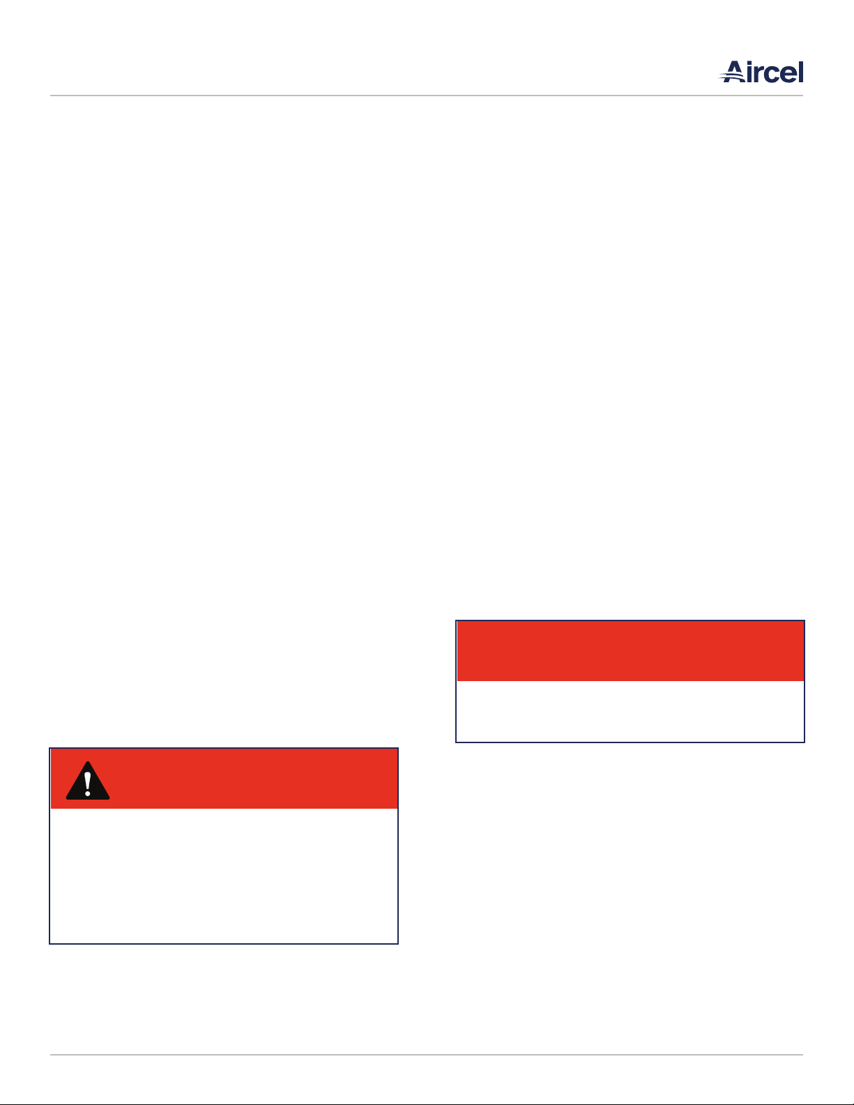
Hot saturated air enters the air-to-air heat exchanger of the
refrigerated air dryer and is pre-cooled by the outgoing dry
air. Pre-cooling saves energy by reducing the heat load on
the dryer’s compressor. The cool saturated air enters the
air-to-refrigerant heat exchanger where air temperature is
lowered to the 38 to 42°F range. This dramatic temperature
drop condenses water and oil.
The mixture of cold air and condensation then flows into the
two-stage separator filter where liquids and contaminants
are removed by centrifugal action, directional flow change,
and velocity reduction. Once bulk liquids have been
removed, the compressed air goes through a stainless steel
mist eliminating filter that coalesces oil aerosols and oil
vapors within the 50-micron range, and then separates and
removes them. At this point, the compressed air is dry and
virtually oil-free.
Cold, dry air exits through the pre-cooler heat exchanger
and is reheated by incoming hot air. Reheating restores
energy and also prevents condensation from forming on
the outside of air distribution piping. In the refrigeration
unit, the compressor pumps hot, high-pressure gaseous
refrigerant to the condenser where it is cooled and liquefied
by ambient air. From the condenser, liquid refrigerant first
flows through the receiver, then through a filter/dryer, and
finally through the expansion valve where pressure and
temperature are reduced. This reduction in pressure causes
the liquid refrigerant to boil until it reaches the saturation
temperature that corresponds to its pressure. As the low-
pressure refrigerant passes through the evaporator, heat
flows from the compressed air to the refrigerant, causing
the boiling to continue until all refrigerant is vaporized.
Refrigerant gas is returned to the compressor and the cycle
is repeated.
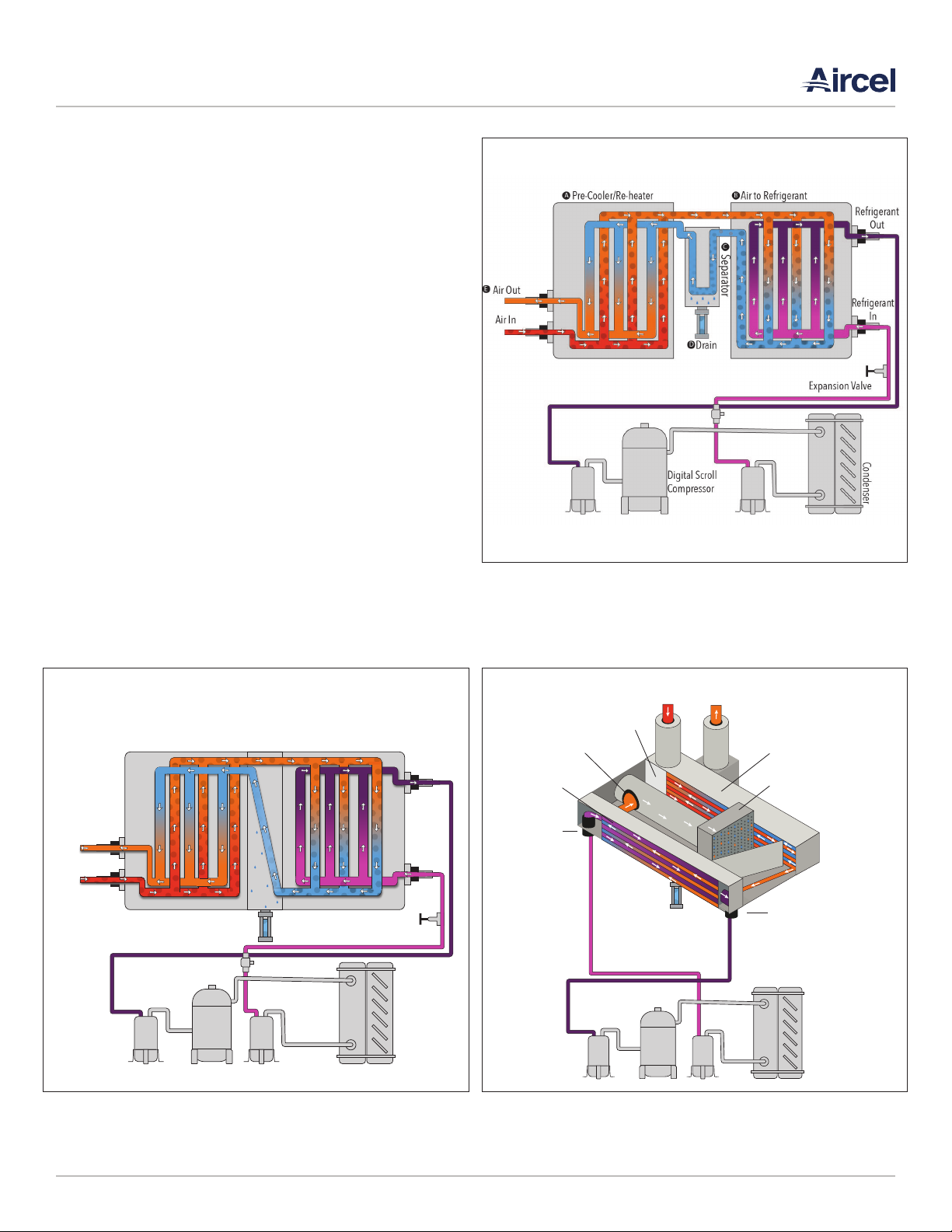
In the VF and DHT Series dryers, a hot gas by-pass valve is
used to control temperature in the evaporator. In the AES
Series, the Copeland Scroll Digital™ compressor allows the
system to eliminate the need for a hot gas by-pass valve.
The closed loop digital controller continuously monitors the
evaporator temperature and modulates the loading and
unloading of the refrigeration compressor based on current
load conditions.
2.3 Refrigeration Circuit
Refrigerant is cycled through a closed loop system commonly
known as high pressure and low pressure. Refrigerant
is compressed by the compressor to a gas with high
temperature and high pressure, which then travels to the
condenser (air- or water-cooled) to lower the temperature
and condense the gas into a liquid. Liquid travels to the
evaporator (refrigerant-to-air part of the heat exchanger)
and back to the compressor suction side. The process then
repeats. A hot gas by-pass valve is used on the non-cycling
VF Series dryers as a freeze protector in low load conditions
(100 scfm rated models [1/2 Hp] and up).
2.3.1 TYPES OF REFRIGERANT USED
R-134a refrigerant is used in dryer models rated 1200 scfm
and below, while R-404A is used in the VF-1600 and higher.
R-134a is a pure refrigerant providing consistent
performance (zero temperature glide) and easy service (no
mixture of different refrigerants). R-404A is a blend of three
pure refrigerants: 52% R-143A, 44% R-125, and 4% R134A
(by mass). This blend is nearly azeotropic meaning it has a
negligible temperature glide. R404A is well suited to larger
is nearly azeotropic meaning it has a negligible temperature
glide. R404A is well suited to larger equipment as the higher
operating pressures and improved heat transfer properties
allow for smaller condensers, which leads to air dryers with
smaller footprints.
2.4 Compressed Air Circuit
The compressed air dryer circuit uses a patented air-to-air
heat exchanger (VF Series 50 scfm and up, DHT Series 40
scfm and up), and stainless steel brazed plate air-to-air heat
exchanger (AES Series). These heat exchangers act as a pre-
cooler/reheater. Hot, saturated, compressed air first enters
the air-to-air heat exchanger, where it is pre-cooled by
outgoing air from the air-to-refrigerant heat exchanger. This
energy saving heat exchanger provides several advantages,
SECTION 2: DESCRIPTION

VF, DHT, AES Series Manual |
Refrigerated Air Dryer User Manual 5
such as a reduction of the heat load imposed on the refrigerant
compressor and condenser, providing more energy to the
outlet air, and preventing condensation of moisture on the
outside of the plant distribution air line piping. From the air-
to-air heat exchanger, air will enter into the evaporator further
reducing its temperature to a desired pressure dew point.
As the air is cooled, moisture is condensed, separated, and
discharged through the condensate drain. The cooled air then
reenters the air-to-air heat exchanger, in a direction opposite
to the flow of the warm, saturated incoming air. This counter
flow action assures high temperature differential throughout
the heat exchanger, resulting in a more effective heat transfer.
Condenser
Compressor
Expansion Valve
Separator
Pre-Cooler/Re-heater Air to Refrigerant
Drain
Refrigerant
Out
Refrigerant
In
Air In
Air Out
Condenser
Compressor
Drain
Refrigerant Inlet
Air-to-Refrigerant
Heat Exchanger
Air Inlet
Pre-Cooler /
Re-Heater
Separator
Air Outlet
Air-to-Air Heat Exchanger
Stainless Steel Mist Eliminator
Refrigerant Oulet
FIGURE 2-2: TYPICAL SCHEMATIC FLOW DIAGRAM
VF Series 10 - 60; 1,600 - 2,000 scfm rated models
DHT Series 20 scfm rated model
FIGURE 2-3: TYPICAL SCHEMATIC FLOW DIAGRAM
VF Series 75 - 1,000 scfm rated models
DHT Series 40 - 125 scfm rated model
FIGURE 2-1: TYPICAL SCHEMATIC FLOW DIAGRAM
AES Series 600 - 10,000 scfm rated models

| VF, DHT, AES Series Manual
Refrigerated Air Dryer User Manual
6
2.5 Digital Scroll Compressor
Aircel AES Series dryers employ the Copeland Scroll Digital™
compressor to allow consistent dew point performance
while matching load proportionally. The modulation of the
compressor is possible through the unique feature called
axial compliance. This allows the compressor to operate
in two stages – the loaded and unloaded state. AES Series
600 – 1500 scfm models feature an external solenoid valve
that connects the modulation chamber on the top of the
compressor with the suction side. AES Series 1750 and
2000 scfm models, the components are integrated into the
compressor housing. When the solenoid valve is energized,
suction gases causes the top scroll to axially separate. When
the scrolls are separated, the compression of the gas is
interrupted.
When the compressor is unloaded the motor still rotates
at the normal speed, however no work is being performed.
Electrical consumption is reduced to approximately 10% of
full load conditions.
A cycle time is comprised of one loaded state time and
one unloaded state time. The duration of these states is
determined by a closed loop controller, which monitors
the temperature of the evaporator. The controller is set to
have a cycle time of 10 seconds. The percentage of loaded
vs. unloaded determines the capacity of the refrigeration
system. For example, if the loaded state is 5 seconds
and the unloaded state is 5 seconds, the compressor
modulation is equal to 50% output. If the compressor
loaded state time is 8 seconds and the unloaded state is 2
seconds, the compressor modulation is 80%. The capacity
is the time average of the loaded state and the unloaded
state. By varying the states the compressor is able to have
any refrigeration capacity between 10% and 100%.
100
90
80
70
60
50
40
30
20
10
0
0 10 20 30 40 50 60 70 80 90 100
Air Load %
Energy Consumption %
Key
AES Series
Non-Cycling
FIGURE 2-4: Graphic of Digital Scroll Operation. The top
view shows the compressor loaded with compression taking
place. The bottom view shows the scrolls separated and no
compression taking place.
FIGURE 2-5: Energy Consumption vs Inlet Load. Graph shows
difference in energy consumption between general, non-cycling
refrigerated air dryers and AES Series Energy Saving, Digital
Scroll refrigerated air dryers.

VF, DHT, AES Series Manual |
Refrigerated Air Dryer User Manual 7
3.1 Inspection on Arrival
All non-cycling refrigerated air dryers are tested and operated
before shipment. However, shipping stresses have the potential
to cause damage to the unit. To ensure smooth installation, it
is recommended that immediately upon receipt of the unit, the
system is checked for the following:
1. Report any damage to the delivery carrier.
2. Request a written inspection report from the Claims
Inspector to substantiate the claim.
3. File claims with the delivery carrier.
4. Compare unit received with description of product ordered.
Check the serial plate label and make sure that it is the
correct Model was ordered. Note the equipment Capacity
and Power Supply requirements and ensure that they are in
accordance with your specifications. The rated conditions
of the dryer are indicated on the serial plate label. If there
is any discrepancy, contact your representative listed on
the manual back cover.
5. Shipping stresses can loosen connections. All pipe and
tubing connections should be inspected.
6. Observe pressure of refrigerant suctions gauge to
determine if refrigerant has leaked during transit. If the
gauge reading does not match that mentioned on the
serial plate label, immediately contact Technical Support
listed on the manual back cover.
7. Report incomplete shipments to the delivery carrier and
your service representative.
3.2 Lifting Information
1. Use all lifting points provided. Special care must be used
when lifting the dryer to prevent tip-over.
2. Use clevis connectors, not hooks, on lifting slings.
3. Only lift unit under support frame/base by using the fork
lift openings provided. Do not lift by piping.
4. Check the approximate weight provided on the specification
control drawing to ensure adequate lift truck capacity.
5. Allow only qualified operators to lift the equipment.
6. Refer to applicable OSHA regulations and local codes when
using cranes, forklifts, and other lifting equipment.
SECTION 3: INSTALLATION
WARNING!
Lifting Hazard
Failure to lift the unit correctly can result in severe
personal injury or property damage.
• Use appropriate lifting equipment and adopt
all safety precautions needed for moving and
handling the equipment.
• A hand cart, forklift, or crane is recommended for
unloading and installation.
• Lift unit by lifting lugs and frame only. Do not lift
by piping.

| VF, DHT, AES Series Manual
Refrigerated Air Dryer User Manual
8
3.3 Installation Codes and Procedures
• Safe and efficient operation of the unit depends on proper
installation.
• Authorities with jurisdiction should be consulted before
installing to verify local codes and installation procedures.
In the absence of such codes, install unit according to the
National Electric Code and NFPA No. 70-latest edition.
• A qualified installation and service agent versed in all
regulatory codes must complete installation of this unit.
3.4 Locating and Installing the Dryer
1. Locate unit on a level foundation. Dryer should be mounted
on a suitably structured flat and level floor or base that is
free from vibration.
2. Install unit to provide adequate clearance for maintenance
services. Dryer and accompanying filters should be installed
with at least 2 to 5 feet clearance from the adjoining walls
to provide easy access for routine maintenance and
adequate air flow across the condensing coil.
3. The frame or cabinet must be securely bolted to the
foundation to prevent movement resulting from earth
tremors and induced piping vibration.
4. Install unit using the correct pipe size and pressure rating.
See drawing package provided with the unit. Connect the
inlet of the dryer to the moist gas from the inlet filter.
Install the inlet piping and the inlet shutoff valve. Install the
outlet piping and the outlet shutoff valve (a union with a
valve by-pass can be installed at the inlet and outlet valves
to accommodate isolation of the dryer for maintenance).
Compressed air piping has to be at least the same size as
that of the inlet and outlet connections of the dryer. Larger
pipe sizes can be used with appropriately rated reducers.
5. Optional system configuration: Install a dryer bypass or
isolation valve to allow isolation of the dryer for service and
maintenance without interrupting the compressed air flow.
6. Minimum recommended filtration: Install an Aircel inline
compressed air particulate pre-filter before the dryer to
protect it against dirt and possible clogging of the heat
exchanger.
7. Additional recommended filtration: Install an Aircel inline
compressed air coalescing after filter after the dryer.
8. Provide adequate power supply. See Section A: Specifications.
Make all electrical connections to the dryer as shown on the
wiring diagram. Special care must be taken in connecting
the proper voltage as indicated on the specification sheet
and wiring schematic. Three phase units are equipped with
a phase monitor, which will prevent unit from operating
when wired in reverse. It is mandatory that the dryer be
grounded. Use of your plant’s frame as a ground may
cause problems with the controls. A fused disconnect is
not supplied with this equipment; therefore, one must be
supplied by customer. All electrical fuses, breakers, etc.
WARNING!
Electric Shock Hazard
This machine is connected to high-voltage power,
which can cause severe electrical shock and injury.
• Follow proper lock out/tag out procedures before
performing service or maintenance work.
• Electrical installation must be performed by a
qualied electrician and comply with all applicable
national and local codes.
WARNING!
Inappropriate tools hazard
Using inappropriate tools for installation or
maintenance work can lead to personal injury or
property damage.
Appropriate tools must be used for all installation and
matinenance work.
WARNING!
Pressure and temperature hazards
Operation at elevated pressure or temperature
may cause damage to the dryer or serious injury to
personnel.
Each dryer is checked at the factory for proper
operation at the conditions noted on the serial plate
label.

VF, DHT, AES Series Manual |
Refrigerated Air Dryer User Manual 9
should be sized by a qualified electrician and comply with
all applicable national and local codes. Our company is
not liable for any code violations, component damage,
downtime or consequential damage related to customer
supplied electrical components and connections.
9. The ambient temperature should be between 40 °F and
100 °F. Low temperature could affect the dryer process
and result in high outlet dew point. In conditions where
the ambient drops below freezing, it is recommended that
a heat trace be used for the equipment. This will ensure
trouble-free operation during the winter months (the dew
point of the outlet air will be consistent).
• In some cases, a head pressure control valve may be
needed. (Optional)
10. Do not place the system in service until the above steps
have been completed and that all ratings and specifications
have been verified to match the requirements in the
drawing package supplied with the unit.
11. If there are any changes in the operating conditions of
the system from those published in this manual, contact
Technical Support.
3.4.1 AIR-COOLED CONDENSER REQUIREMENTS
Cooling air must be drawn from a clean source to reduce dust
and dirt accumulation on the condenser coils. Air temperature
should not exceed 100°F (38°C).
3.4.2 COOLING WATER REQUIREMENTS (WATER-
COOLED CONDENSING UNITS)
Cooling water is required for water-cooled refrigerant
condensers (scfm rated model 100 and up). The user is
responsible for piping the water to and from the condenser.
The required water flow rate depends on the water
temperature. A water-regulating valve (supplied with the dryer)
automatically adjusts the flow to compensate for variation in
water temperature, water pressure, and dryer air load. The
table below indicates the amount of cooling water required
in gallons per minute (gpm) at given incoming temperatures
for the condenser Hp size in each model. The refrigerant
discharge pressure control will shut down the refrigerant
compressor if cooling is inadequate.
NOTICE:
• Water cooled condensers are pre-set at the factory for city
water usage.
• Water regulating valve may need to be adjusted to other
water supply conditions. Contact technical support for
assistance.
• Minimum water pressure is 25 psig for city water and 35
psig for tower water. Cooling water pressures less than
these minimums may reduce dryer drying capacity.
• Maximum water pressure is 125 – 150 psig.
• Water flow rate requirements must be increased by 10%
for seawater cooled condensers (Assuming 3.5% salinity
at 77°F.
Drain
Valve
Air or Water
Cooled
Condenser
Air
Compressor
Drain
Valve
Dry Air
to Plant
Drain
Valve
Refrigerated Dryer
After Filter
Pre-Filter
Wet Receiver
(optional)
Dry Receiver
(optional)
Separator
Drain
Valve
FIGURE 3-1: Typical Installation Setup

| VF, DHT, AES Series Manual
Refrigerated Air Dryer User Manual
10
Model by SCFM
Rating Refrigeration HP
Cooling Air Flow
(cfm)
10, 15, 25 0.20 275
40, 50 0.25 300
60, 75 0.33 300
100 0.50 350
125, 150 0.75 525
200 1.25 750
250, 300 1.50 1,250
400 2 3,000
500, 600 3.50 3,000
800, 1000 5 5,000
1,200 6 5,000
1,600 7 6,000
2,000 10 6,000
Model by SCFM
Rating Refrigeration HP
Cooling Air Flow
(cfm)
20 0.33 300
40 0.50 350
50 0.50 350
75 0.75 525
100 0.75 525
125 1.25 750
TABLE 3-1: Air-Cooled Cooling Air Flow -
VF Series
TABLE 3-2: Air-Cooled Cooling Air Flow -
DHT Series
TABLE 3-3: Air-Cooled Cooling Air Flow -
AES Series
Model by SCFM
Rating Refrigeration HP
Cooling Air Flow
(cfm)
600 3.0 3,000
800 4.0 4,500
1,000 5.0 5,000
1,250 6.0 5,000
1,500 7.5 5,500
1,750 & 2,000 10.0 6,000
*Requirements are per module

VF, DHT, AES Series Manual |
Refrigerated Air Dryer User Manual 11
Incoming Water Flow Rate Requirements
(in gpm at dierent inlet water temperature)
Model by SCFM
Rating Condenser HP 70°F 80°F 85°F 90°F
100 0.50 1.50 1.75 2 C/F
125, 150 0.75 2.50 2.75 3 C/F
200 1.25 2.50 2.75 3 C/F
250, 300 1.50 4 4.50 5 C/F
400 2 5 5.50 6 C/F
500, 600 3.50 8 9 10 C/F
800 5 8 9 10 C/F
1,000 5 13 14.50 16 C/F
1,200 6 14 16 18 C/F
1,600 7 18 20 22 C/F
2,000 10 26 29 32 C/F
TABLE 3-4: Water-Cooled Water Flow Requirements- VF Series
TABLE 3-5: Water-Cooled Water Flow Requirements- DHT Series
Incoming Water Flow Rate Requirements
(in gpm at dierent inlet water temperature)
Model by SCFM
Rating Condenser HP 70°F 80°F 85°F 90°F
40,50 0.50 1.50 1.75 2 C/F
75,100 0.75 2.50 2.75 3 C/F
125 1.25 2.50 2.75 3 C/F

| VF, DHT, AES Series Manual
Refrigerated Air Dryer User Manual
12
3.5 Preliminary Start-Up Checklist 1. Check that the inlet and outlet connections are the correct
size and pressure rating, and tightened securely.
2. Check that the correct power supply is connected to the
non-cycling refrigerated air dryer system with an adequate
disconnect switch.
3. Check that all compressed air line service valves are open
and that compressed air is available to be supplied to the
non-cycling refrigerated air dryer system.
4. Check that all liquid drain service valves are open. This is
to ensure that any residual bulk condensate that may have
accumulated in the compressed air lines is discharged
immediately upon start up. These drains must be closed
once system is brought on line for use. The drain valve on
the refrigerated air dryer can be opened by pushing the
test button located on the drain body.
5. With the customer-supplied compressed air to the system,
OPEN the inlet valve slowly to gradually pressurize the
system. Do not open valve too quickly. Opening valve and
suddenly pressurizing the system can cause damage to the
dryer heat exchanger and other components.
6. Check the air system piping connections and dryer system
connections for leaks at this time. Repair and retest any
leaks.
7. Verify that all instrumentation (pressure gauge/s) and
drain air tubing fittings are tight.
Incoming Water Flow Rate Requirements
(in gpm at dierent inlet water temperature)
Model by SCFM
Rating Condenser HP 70°F 80°F 85°F 90°F
600 3.0 8 9 10 C/F
800 4 8 9 10 C/F
1,000 5 13 14.5 16 C/F
1,250 6 14 16 18 C/F
1,500 7.5 18 20 22 C/F
1,750 & 2,000 10 26 29 32 C/F
TABLE 3-6: Water-Cooled Water Flow Requirements- AES Series
*Requirements are per module
C/F: Consult Factory
NOTICE
• For single-phase models, wait at least six (6) hours
after transporting or moving of dryer system
before starting the dryers. Turn the main power
switch to the dryer on, but do not turn the dryer
on/o switch to the on position until six (6) hours
have passed.
• For three-phase models, ensure that the power
switch is in the “o” position, but the electrical
service to the dryer is energized. This dryer must
be in this mode for at least twelve (12) hours
to allow the compressor crankcase heater to
energize and evaporate any liquid refrigerant
from the compressor. After twelve (12) hours,
turn on the power switch of the dryer. The power
indicating light should turn on.

VF, DHT, AES Series Manual |
Refrigerated Air Dryer User Manual 13
8. Ensure that the air system has come up to full pressure and
has filled the dryer with compressed air. Before opening
the outlet valve on the system and after the dryer has been
started under no load, let the dryer run for at least fifteen
(15) minutes to allow stabilization of the system. Verify the
following:
a. The dryer is designed to run continually and should
not be cycling on and off with the air compressor. The
non-cycling operation of the dryer is controlled by an
automatic expansion valve or a thermostatic expansion
valve / hot gas by-pass valve. The valves will open and
close automatically depending on the of heat load to
the evaporator, thus maintaining the desired pressure
dew point.
b. Check the inlet compressed air temperature and
pressure to the dryer and verify that it meets the
specified requirements.
c. Fan rotation, for dryers with an air-cooled condenser,
rotation should be in accordance with the fan rotation
shown on the details located on top and back of the
condenser. Cooling air is drawn through the condenser
coils. Three phase units are equipped with three phase
monitors, which will prevent the fan(s) and compressor
from running backwards. The unit will not turn on
unless the wire leads are in the correct location. The
phase monitor, located in the electrical box, will display
a green light, when the unit is phased properly. A red
light indicates that the unit is not phased properly. If the
motor rotation is not correct, turn off the power switch
and put the main power supply disconnect in the “off”
position; lock and tag; check the wiring; correct the wire
lead locations; recheck for correct phasing.
d. The refrigeration gauge readings should be as follows:
• Refrigerant suction pressure
R-134a = 28-40 psig
R-404a = 75-90 psig
• Refrigerant discharge pressure
R-134a = 160-230 psig
R-404a = 290-400 psig
9. After the preliminary start up checklist has been completed,
the compressed air outlet valve on the dryer system can
now be slowly opened to supply clean dry compressed air
to the facility.
10. After start-up and approximately one month of service,
check that all piping and fittings are tight and free of leaks.
3.6 Automatic Drain Valve Adjustments
The automatic drain valve supplied is standard on the separator
and should open regularly and discharge any accumulated
water into the drain line. The period between openings varies
with the dryer and operating conditions (electronic type). To
minimize air losses, the timer should be adjusted to open the
drain solenoid just long enough to discharge the accumulated
condensate. The factory sets the automatic drains to open for
7 seconds about every 7 minutes. If more than two seconds
of dry air comes out at the end of every discharge cycle,
reduce the open time (seconds) or increase the interval of the
discharge (minutes) to minimize air loss. If liquid is still being
discharged when the discharge cycle stops, increase the open
time (seconds) or shorten the interval of discharges (minutes)
so it discharges more often.
3.7 Zero Loss Condensate Drain
Aircel AES dryers are supplied with zero air loss condensate
drains standard on the separator and after the evaporator.
These drains should be checked regularly via the test
function to verify proper operation. The period between
openings varies with the operating conditions of the dryer.
The capacitive level sensing technology allows a direct acting
valve to discharge condensate without losing compressed air.
Unlike timer drains, these drains do not need to be adjusted.
The drain is equipped with an alarm feature. The alarm will
activate if the valve opens too many consecutive times without
a pause. If the alarm is activated check to see if debris is
blocking the valve or outlet.
NOTICE
The above discharge pressure depend upon ambient
temperature and can vary slightly according to
temperature uctuations.
NOTICE
• Models with the hot gas by-pass valves and
expansion valves are preset at the factory for
the desired dew point. Do not adjust without
consulting with the factory.*
• The dryers are fully automatic and do not require
any auxiliary controls.
* Adjustments not authorized by the factory may void the
warranty.

| VF, DHT, AES Series Manual
Refrigerated Air Dryer User Manual
14
4.1 Operating Procedures
After the initial startup, the dryer operation is completely
automatic. To understand the details of the operation, see
Figure 2-1: Typical Schematic Flow Chart on page 4.
4.2 Short-Term Shut Down
(Over Night or Weekends)
The refrigerated air dryer system can be shut down at any time
by turning the unit off at the dryer by using the on/off switch or
at the main disconnect switch.
4.3 Shut Down Emergency
The non-cycling refrigerated air dryer system can be shut down
under any conditions and at any time by turning the unit off
at the dryer or at the main disconnect switch. Once power is
removed from the dryer system, the dryer must be isolated
from the compressed air stream to avoid a refrigeration circuit
over pressure situation.
SECTION 4: OPERATION
WARNING!
Pressure Hazard
This machine contains contents under high pressure,
which can cause severe injury.
• To avoid possible hazard or injury, the operator
should be fully familiar with the refrigerated air
dryer system and its operation.
• When the system is shutdown and power removed,
lock out power supply and depressurize system
before performing maintenance or service work to
avoid injury to personnel or property damage.
NOTICE
Before running compressed air ow through the dryer,
run the dryer for 15 minutes to stabilize temperature.

VF, DHT, AES Series Manual |
Refrigerated Air Dryer User Manual 15
SECTION 5: CONTROLLERS (AES SERIES)
5.1 Home Screen
The main screen allows the user to view critical operating
conditions of the unit: suction and discharge pressures.
suction and discharge temperatures, dryer load, compressor
off/on status, fans off/on status, unloader off/on status as
well as navigation to the other screens. The functions are as
follows:
• STATUS SCREEN: Navigates to the status screen
• INFO SCREEN: Navigates to the info screen
• ALARM SCREEN: Navigates to the alarm status screen
• ALARM LOG: Navigates to the alarm log screen
• SUCTION PSI: Shows the suction pressure of the unit
• SUCTION °F: Shows the suction temperature of the unit
• DISCHARGE PSI: Shows the discharge pressure of the unit
• DISCHARGE °F: Shows the discharge temperature of the
unit
• DRYER LOAD %: Shows the percentage of the dryer load
• COMPRESSOR OFF/ON: Indicates whether the compressor
is off or on. Green indicates ON.
• FAN 1 OFF/ON: Indicates whether fan 1 is off or on. Green
indicates ON.
• FAN 2 OFF/ON: Indicates whether fan 2 is off or on. Green
indicates OFF.
• UNLOADER OFF/ON: Indicates whether the unloader is off
or on. Green indicates ON.
• NO ALARM: Displays the alarm indication. When NO
ALARM is indicated, the unit is in working order. When
an alarm is active, the indication will be red and will
read COMMON ALARM. To see which alarms are active,
navigate to the ALARM SCREEN. To view when the alarm
occurred, navigate to the ALARM LOG.
FIGURE 5-1: Home Screen

| VF, DHT, AES Series Manual
Refrigerated Air Dryer User Manual
16
5.3 Information Screen
The information screen gives alarm information from the
Performance Alert module located in the condensing unit
electrical enclosure. The Performance Alert module will flash
a yellow light to indicate certain alarms (for example: the light
will flash twice for a system trip alarm)
• MAIN SCREEN: Navigates to the main screen
• INFO SCREEN: Navigates to the info screen
• ALARM SCREEN: Navigates to the alarm status screen
• ALARM LOG: Navigates to the alarm log screen
5.2 Status Screen
The status screen shows the user the compressor hours of
operation, fan hours of operation, total hours of operation,
and total savings hours.
• MAIN SCREEN: Navigates to the main screen
• INFO SCREEN: Navigates to the info screen
• ALARM SCREEN: Navigates to the alarm status screen
• ALARM LOG: Navigates to the alarm log screen
FIGURE 5-2: Status Screen FIGURE 5-3: Information Screen
This manual suits for next models
34
Table of contents
Other Aircel Dryer manuals
Popular Dryer manuals by other brands

Dyson
Dyson Airblade 9KJ Installation Instructions and Maintenance Manual

Hotpoint
Hotpoint TVFS 73 Instruction booklet

GE
GE DMCD330EJ3WC installation instructions

AEG
AEG LAVATHERM 75470AH user manual

Zanussi
Zanussi ZI 930 Instructions for use and care

Hotpoint
Hotpoint AQUALTIS AAQCF 81 U Instruction booklet