Airdog II DF-165 User manual

PureFlow AirDog®
AirDog® II-5G DF-165 1999-2003 7.3L Ford Powerstroke
PROTECTED BY
CANADIAN PATENT US PATENTS AUSTRALIAN PATENT
2,108,391 5,355,860; 5,746,184; 6,729,310 2005101054
NEW ZEALAND PATENT
532356
Additional Foreign Patents Pending in Europe, South America, Mexico, Japan, and China!
#58

PureFlow AirDog®
AirDog® II-5G DF-165 1999-2003 Ford 7.3L Powerstroke
2
SMALL and COMPACT
7” Long X 3.2” Wide X 10” Tall

PureFlow AirDog®
AirDog® II-5G DF-165 1999-2003 Ford Powerstroke
3
OVERVIEW
Thank you for your purchase and welcome to PureFlow AirDog’s AirDog®II-5G fuel air
separation and delivery system for the 1999-2003 7.3L.
The AirDog®II-5G is an all in one premium fuel pump and filtration system for the 7.3L.
This system removes water, particulates, and entrained air from the diesel fuel. The
entrained air that is separated from the fuel is returned to the tank through a small return
fitting. The fuel is delivered to the engine at the correct pressure and flow rate to meet the
demands of the engine under all operating conditions.
The AirDog®II-5G DF-165 systems feature a built in adjustible diaphragm pressure
regulator. All AirDog®II-5G systems include a complete installation kit.
The AirDog®II-5G, for this particular application, is preset at 55-60psi from factory for
a stock application. The regulator is adjustible up to 70 psi for fine tuning the system for
performance upgrades. WARNING: RUNNING THE PUMP ABOVE 70PSI WILL DECREASE THE
LIFE OF THE PUMP SIGNIFICANTLY AND MAY VOID THE WARRANTY.
PureFlow AirDog products are manufactured in Shelbyville Indiana by a team of skilled
workers with unsurpassed attention to detail and using the most stringent quality assurance.
HOW THE 5G OPERATES
The AirDog®II-5G DF-165 draws fuel from the fuel tank. The fuel is then drawn through the
water separator where 92% of water is removed per SAE spec 1488. It is then pressurized
through a Gerotor pump and sent to the 2 micron fuel filter before it is sent to the injection
pump. The air from aerated fuel, due to tank sloshing and engine return lines, is separated
and sent back to the tank through the 3/8” return fitting. The excess fuel that the engine
does not use is recirculated through the diaphragm regulator back to the suction side of the
pump.

PureFlow AirDog®
AirDog® II-5G DF-165 1999-2003 Ford Powerstroke
4
QUICK CONNECT COMPONENT OVERVIEW
Provided in this kit is an OE style quick connection system. This system works to
allow a quick, clean, and professional install.
SAE J2044 Quick Connect System
The SAE J2044 quick connect system is the most commonly used system in the
automotive industry. The images below show the formation of SAE J2044
connection. To connect the assemblies, simply insert the male end form into
the mating female connector. Push firmly until you hear it “click” into place. To
disconnect the fittings, press down and hold the tabs on the female connector
while you firmly pull the assembly apart.

PureFlow AirDog®
AirDog® II-5G DF-165 1999-2003 7.3L Ford Powerstroke
Section 1 Table of Contents
5
TABLE OF CONTENTS
Section 1……………………….……….…….……..…....…Table of Contents
Section 2…………..…………………...…Installation and Safety Guidelines
Section 3……………………..…….…….….………………….…….Parts List
INSTALLATION PROCEDURES
Section 4……………………………..……..Fittings, Brackets, and Mounting
Fuel Lines
Section 5………………………………………..…………Fuel Line Assembly
Section 6A……………………….…..……..........….…Supply Line to Engine
Section 6B…………………….......…….........................Return Line to Tank
Section 6C…………………….……...…………...….Suction Line from Tank
Electrical Harness
Section 7…..……………………………….…...…...…..……..Wiring Harness
Section 8..………….………………….………..……Initial Startup Procedure
Maintenance
Section 9………………….………….....…Filter Service Recommendations
Section 10……………..………..…………...Cleaning the Gerotor Assembly
Section 11…………………………………. Pressure Regulator Adjustment
Section 12…………………………………………………..Filter Maintenance
Section13………………………………………………....Warranty Procedure

PureFlow AirDog®
AirDog® II-5G DF-165 1999-2003 7.3L Ford Powerstroke
Section 2 Installation and Safety Guidelines
6
AirDog®II-5G MODEL DF-165
INSTALLATION GUIDELINES
The installation of your AirDog®II-5G can be relatively easy by following the steps outlined in
this manual, and:
1. Inventory the package components completely. Notify PUREFLOW AIRDOG immediately
of any missing or damaged parts. (877-421-3187)
2. Read the installation manual completely. Understand how the system operates and take
note of installation recommendations before beginning installation.
3. The installation recommendations contained herein are suggested installation guidelines
only. Individual installations may vary.
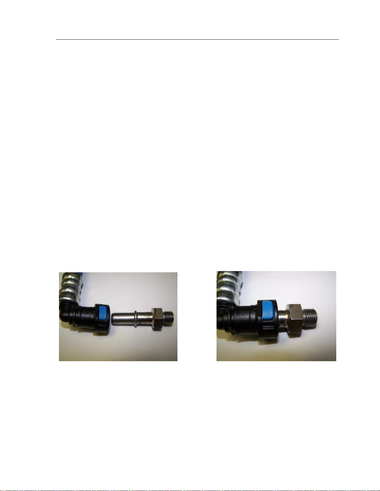
4. When installing the AirDog®II-5G fuel lines, be sure to connect the ORIGINAL ENGINE
RETURN LINE to the fuel tank as it was from the factory when the installation is complete!
If any installation procedure is uncertain, contact
PUREFLOW AIRDOG for technical assistance.
SAFETY GUIDELINES!
CAUTION! Be sure to chock the vehicle’s tires to prevent rolling.
CAUTION! Use proper supports when working beneath an elevated vehicle.
CAUTION! Most diesel pickups have two (2) 12volt batteries. Disconnect the battery
cables to both batteries before proceeding with the AirDog®II-5G installation.
CAUTION! Vehicle frame rails should not be drilled into or welded upon.
CAUTION! Wear safety glasses when operating power tools such as drills and grinders or
when using a punch or chisel.
CAUTION! Use common sense when routing fuel lines and electrical harnesses. Keep
them away from hot exhaust components and/or moving parts. Properly
secure lines to prevent chaffing.
NOTE: The pictures used in this manual are for example only and may not be exactly the
same as your truck.

PureFlow AirDog®
AirDog® II DF-165 1999-2003 7.3L Ford Powerstroke
Section 3 Parts List
7
Powerstroke Parts List
QTY
DESCRIPTION
PART NUMBER
IMAGE
1
AirDog®II-5G
DF-165
1
AirDog®II Mounting Bracket
001-3C-0004
1
Mounting Hardware Kit,
901-61-0102-PM-F
1
Frame Bracket
010-3C-0002
010-3C-0001
1
Wiring Harness
5E-2-010-HD
1
Return Fuel Filler Tube (with 2 Clamps)
001-4A-1-0150
1
Bundle of Plastic Ties
5H-2-1-06/12
1
Spacer
010-3C-0003-A-P
1
20ft of Fuel Line
HS20
1
5/16” male J2044 Quick Connect to 1/2” Push Lock Fitting
MQC516
3
1/2” Straight Hose Quick Connect Fitting
FQC12S
2
3/8” 90° Hose Quick Connect Fitting
FQC3890
2
1/2” Male J2004 Quick Connect x 3/4-16” UNF
08J2044-3/4UNF
1
3/8” Male J2004 Quick Connect x 7/16” UNF
06J2044716UNF
1
Customer Service O-ring Replacement Kit
901-05-0100
N/A

PureFlow AirDog®
AirDog® II DF-165 1999-2003 7.3L Ford Powerstroke
8
ILLUSTRATION OF QUICK CONNECT COMPONENTS

PureFlow AirDog®
AirDog® II DF-165 1999-2003 7.3L Ford Powerstroke
Section 4 Fittings, Brackets, and Mounting
9
Installing the Supplied Fittings Into the AirDog II-5G Base
4-1. Dip the threaded end of the 08J2044-3/4UNF fitting into clean motor oil and hand-
thread into the “ENGINE” and “INLET” ports of the AirDog®II-5G filter base as
illustrated in figures 1, 2, and 3. Using a 3/4” deep socket, torque the fittings to 180in-
lb or 15ft-lb. DO NOT overtighten the fittings or damage may occur!
4-2 Dip the threaded end of the 06J2044716UNF fitting into clean motor oil and hand-
thread into the “RETURN” port of the the AirDog®II-5G filter base as illustrated in
figures 1 and 2. Using a 9/16” deep socket, torque the fitting to 84in-lb or 7ft-lb. DO
NOT overtighten the fittings or damage may occur!
Figure 1
Figure 2
Figure 3
RETURN
ENGINE
INLET

PureFlow AirDog®
AirDog® II-5G DF-165 1999-2003 7.3L Ford Powerstroke
Section 4 (Continued) Fittings, Brackets, and Mounting
10
4-3. Assemble the AirDog mounting bracket (001-3C-0004) to the frame bracket (010-3C-
0001) using the spacer (010-3C-0003-A-P) as shown in figure 4 using the four bolts,
lock washers, and nuts included in the mounting bracket hardware kit (figure 5).
Properly torque all fasteners! You will need a 3/16” allen and a 1/2" wrench. The
bracket assembly should look like figure 6.
4-4. Attach the AirDog®II-5G to the frame bracket assembly as shown in figure 7 using the
supplied hardware in the mounting bracket hardware kit. The brackets are universal
and can be mounted anywhere there is room.
NOTE: We recommend installing the AirDog® on the inside of the frame rail, but we
understand some applications just don’t have the room. The photos in this manual may not
be the same as your application.
4-5. Be sure to tuck the AirDog®II-5G as far up as possible without it rubbing on anything
to prevent damage from road debris. The bracket assembly is adjustible to achieve
this.
Figure 4
Figure 5
Figure 6
Figure 7

PureFlow AirDog®
AirDog® II-5G DF-165 1999-2003 7.3L Ford Powerstroke
Section 4 (Continued) Fittings, Brackets, and Mounting
11
4-6. Clamp the frame between the AirDog® bracket assembly and the backing plate (figure
8) using the 3/8” bolts, lock washers, and nuts included in the kit. You will need two
9/16” wrenches. Properly torque all fastners! BE SURE to mount the AirDog®II-5G with
the “INLET” port toward the rear of the vehicle (Figure 8).
Figure 8
VEHICLE
FRONT
VEHICLE
REAR
FUEL IN

PureFlow AirDog®
AirDog® II-5G DF-165 1999-2003 7.3L Ford Powerstroke
Section 5 Fuel Line Assembly
12
Assembling the Fuel Lines
This kit includes a length of fuel line and separate fuel line ends to allow for
much cleaner looking installations! Assemble the fuel lines as you install them.
You won’t want to pre-assemble the hoses or your lengths may be off.
5-1. Take the fuel line end and lubricate the barbed end with clean motor oil (Figure 9) and
press it into the fuel line (HS20) until all three barbs are covered (Figures 10 and 11).
The fuel line end should look like Figure 11.
5-2. Now plug that fuel line with that fitting into the connection on the either the AirDog
or the truck where the manual calls it out.
5-3. Run the fuel line along the frame away from any hot or moving parts such as exhaust
or the driveshaft (Figure 12). Cut the hose to length and insert the other fuel line end
that the manual calls out into the fuel line as outlined in step 5-1.
NOTE: Hose clamps are not needed for these push-lock connectors.
Figure 9
Figure 11
Figure 10
Figure 12

PureFlow AirDog®
AirDog® II-5G DF-165 1999-2003 7.3L Ford Powerstroke
Section 6A Fuel Lines (Supply Line to Engine)
13
AirDog®II Fuel Supply Line to the Engine
6A-1. Disconnect the high pressure fuel supply line to the engine from the OE fuel pump.
This pump is located on the driver’s side inside frame rail.
High Pressure Fuel Pump with 5/16” Quick Connect Fitting
To Engine
6A-2. Push the male, 5/16” J2044 Fitting (MQC516) into HS20 until all three barbs are not
showing, then connect the fitting into the factory fuel supply line that was just
disconnected in the previous step. A “click” will be heard once properly connected.
6A-3. Run the other end of the fuel line along the frame, away from any hot or moving
parts, to the port in the AirDog base labeled “Engine.” Cut the fuel line to length and
press in fuel line end FQC12S per section 5. Once the connector is pressed in, press it
onto the male connector in the filter base in the “Engine” port. A “click”will be heard
when properly connected.
NOTE: The OE fuel pump and fuel line from the fuel tank may be removed from the
vehicle at this time, if desired.
DISCONNECT HERE
Figure 13 FRONT VIEW
Figure 14 REAR VIEW
Figure 15
FQC12S
HS20
Figure 16
HS20
MQC516

PureFlow AirDog®
AirDog® II-5G DF-165 1999-2003 7.3L Ford Powerstroke
Section 6B Fuel Lines (Return Line to Tank)
14
AirDog®II Fuel Return Line
Installing the Filler Neck Tee in the Filler Tube
6B-1. Cut filler tube as illustrated in figure 17. Loose assemble clamps on each end of filler
tube before the filler tube is pushed in.
6B-2. Insert the “Return Fuel Filler Tube” assembly (P/N 001-4A-1-0150) in the filler tube.
INSTALL THE FILLER TUBE WITH ARROWS, WHICH ARE STAMPED IN THE PART,
POINTING TOWARD THE TANK!! SEE FIG 18. Properly tighten clamps.
6B-3. Assemble one end of the hose (Reference section 5) using Fuel line end FQC3890 and
plug it into the “Return” J2044 fitting installed in the AirDog® (Figure 20). A “click” will
be heard once the fitting is properly connected.
6B-4. Run the fuel line along the frame as mentioned in step 5-3 to the filler neck tee. Cut
the fuel line to length and insert fuel line end FQC12S per step 5-1. Once the
connector is installed, connect it to the male J2044 fitting in the filler neck tee (001-
4A-1-0150). A “click” will be heard once properly connected.
Fuel Tank
Hose Clamp
Filler
Tube
Fuel
Return
Fitting
Figure 17
Figure 19
Figure 18
Towards
Tank
Figure 20
FQC3890
HS20
FQC12S
HS20
Figure 21

PureFlow AirDog®
AirDog® II-5G DF-165 1999-2003 7.3L Ford Powerstroke
Section 6C Fuel Lines (Suction Line from Tank)
15
Fuel Suction Line for AirDog®II
6C-1. Remove the original fuel suction line Quick Connect fitting from fuel tank by
squeezing the tabs on the end of the connector together. DO NOT mistake the return
line with the suction line. Consult your factory manual if unsure of these procedures.
In More Detail
To release the quick-connect fitting from the fuel tank suction tube, push the fitting toward
the suction tube. With the plastic tabs firmly depressed, pull the fitting assembly from the
suction tube. Hold the Quick Connect Fitting square to the suction tube. It may be difficult to
disconnect the fitting it is cocked or becomes cocked during removal.
6C-2. Assemble one end of the hose (Reference section 5) using fuel line end FCQ3890 and
plug it into the male connection to where the factory suction line was just removed in
the previous step. A “click” will be heard once properly connected.
6C-3. Run the fuel line along the frame as mentioned in step 5-3 to the AirDog® “Fuel In”
port. Cut the fuel line to length and insert fuel line end FQC12S per step 5-1. Once the
fuel line end is pressed in, connect it to the male J2044 fitting in the AirDog® “Fuel In”
port. A “click” will be heard once properly connected.
VERY IMPORTANT: If the OE High Pressure fuel pump was not
removed from the vehicle, disconnect the power supply lead to the
OE High Pressure Fuel Pump.
Suction Line
Return Line
FQC3890
HS20
Figure 22
Figure 23
Figure 24
FQC12S
HS20
Figure 25
Figure 26

PureFlow AirDog®
AirDog® II-5G DF-165 1999-2003 7.3L Ford Powerstroke
Section 7 Wiring Harness
16
AirDog®Wiring Harness Install
WIRING DIAGRAM
Secure the Relay and Fuse Holder to the Vehicle
7-1. Secure the relay and fuse holder to the vehicle. Be sure to rout the wires away from
any moving parts. The relay is illustrated below in figure 28. The fuse holder mounting
is the same concept.
Figure 28
MINI-TAP RELAY
TRIGGER LEAD
AirDog®
MOTOR LEAD
BATTERY
NEGATIVE LEAD
BATTERY
POSITIVE LEAD
FUSE HOLDER
WITH 20A FUSE
RELAY
Figure 27

PureFlow AirDog®
AirDog® II-5G DF-165 1999-2003 7.3L Ford Powerstroke
Section 7 (Continued) Wiring Harness
17
Connecting the AirDog®Relay Control Lead
7-2. Route the AirDog®'Relay activation lead', to the fuse panel on the dash to the left of
the steering column. Insert the mini fuse tap into a spare fuse holder on the panel
that is “hot” when the starter key is turned to the on position (Figure 29).
7-3 OR if you prefer, route the AirDog®'relay activation lead, 'the Red (+) wire with the
mini fuse tap attached, to the OE fuel pump. Remove the mini fuse tap and splice the
relay lead to the OE fuel pump lead (Figure 30).
NOTE: The power supply leads can be connected to the battery or the alternator. Connecting
the power supply leads to the alternator instead of the battery will create a corrosion free
connection.
7-4. Route the power supply leads to the alternator.
Connect the Black (-) lead to the alternator
Ground connection.
Connect the Red (+) lead to the alternator Hot
Lead going to the battery.
OR
7-5. Should you choose to connect the power
supply leads directly to the battery, connect
the RED (+) lead to the POSITIVE (+) post
of the driver's side battery. Connect the
BLACK (-) lead to the NEGATIVE (-) post
on the same battery.
7-6. Route the wiring harness to the AirDog®
and connect the 2 pin Metri-Pack connector
to the corresponding connector on
the AirDog®.
Figure 29
Figure 30
Red (+)
Black (-)
Figure 31
Figure 32
Figure 33

PureFlow AirDog®
AirDog® II-5G DF-165 1999-2003 7.3L Ford Powerstroke
Section 8 Initial Startup Procedure
18
INITIAL START PROCEDURE
8-1. The AirDog®II is a self-priming system, however, to prevent possible damage to the
system, it is recommended to fill the water separator with diesel fuel before initial
startup.
8-2. Rub diesel fuel or oil on the filter seals before installing to ensure a proper seal.
8-3. Turn the starter key to the on/run position.
8-4. While the AirDog®II is operating, bleed the fuel line to the engine of air by loosening
the fuel line connection at the engine fitting. As soon as the line is purged of air and
pure fuel is observed, properly tighten the fuel fitting. NOTE: put a rag or shop towel
over and around fitting to prevent splatter. Catch all spilled fuel and dispose of
properly. Wear safety glasses.
8-5. Start engine.
RECHECK ALL FUEL FITTINGS FOR LEAKAGE AND PROPERLY TORQUE. BE SURE ALL FUEL
LINES ARE PROPERLY ROUTED TO PROTECT FROM EXCESSIVE HEAT AND SECURED TO
PROTECT FROM CHAFFING AND ABRASION. RECHECK ALL ELECTRICAL LINES, SECURE AS
NECESSARY.
CHECKING FOR EXCESSIVE PUMP NOISE
NOTE: Each AirDog®II has been manufactured in a Quality Controlled process and wet tested
for operation and performance before shipment. This is a smooth running system. With fuel
or air alone, the AirDog®II fuel pump will run quietly. However, if any fuel fitting on the
vacuum side, between the fuel tank and the AirDog®II or the pre-filter has been left loose
during the installation process, the system may be sucking air at an excessive rate and will be
very noisy. Excessive restriction in the suction line from the fuel tank can cause vapor and
noise, as well. To check for these problems, unscrew the pre-filter 3 or 4 full turns and
activate the AirDog®II by turning the ignition switch to on If the AirDog®II runs quietly, then
excessive air from a loose fitting or leaking pre-filter seal or vapor from fuel flow restriction is
most likely the reason for the excessive noise. Correct as necessary.
A. The seal groove in the 3” filter is a snug fit and on occasion the seal has been found to
not be fully seated. Remove the pre-filter, remove the seal from the top of the nut
plate. Clean and lubricate the seal grove. Carefully replace the seal in the grove. Be
sure to fully seat the seal.
B. Check all fittings, especially the quick connect at the tank.

PureFlow AirDog®
AirDog® II-5G DF-165 1999-2003 7.3L Ford Powerstroke
Section 9 Fuel Filter and Water Separator
19
AirDog®
WATER
SEPARATOR
AirDog®
2 MICRON
FUEL FILTER
WATER DRAIN
VALVE
FILTER SERVICE RECOMMENDATIONS
Plugging of either the fuel filter or the water separator itself will cause low fuel pressure and
low flow to the engine. If a low fuel pressure issue exists, replace the fuel filter. Typical fuel
filter life is 15-20k miles depending on fuel quality.
The Water Separator
Replace the water separator every other time you change the Fuel Filter or if it becomes
damaged or plugged. It is suggested to check/drain the water separator every three months
or as needed should you experience excessive ‘water in fuel’ conditions. When installing the
water separator, be sure to clean the underside of the AirDog® base. Follow the instructions
printed on the pre-filter for proper tightening procedures.
CAUTION: Be extremely careful to prevent any contaminates or debris from entering the pre-
filter when removing it for cleaning! Large debris will jam the Gerotor and cause the fuse to
blow. This is not a warranty item. Should this happen, you can easily put the system back into
working order. See the instructions on “How to clean the Gerotor” for proper procedures.
The Fuel Filter
Remove the fuel filter by turning it counter clockwise. DO NOT pre-fill the fuel filter with fuel.
The AirDog® will fill the filter and prime the system automatically. Follow the instructions on
the filter for proper tightening procedures.
CAUTION: Dispose of waste fuel and used filters properly

PureFlow AirDog®
AirDog® II-5G DF-165 1999-2003 7.3L Ford Powerstroke
Section 10 Cleaning the Gerotor Assembly
20
STEP 1: Remove the four (4)
socket head cap screws that
secure the Gerotor cap using
a 3/16 allen wrench.
STEP 2: Carefully remove
the O-rings you will need to
reuse them.
STEP 3: Remove and clean
the Gerotor. Be very careful
to not damage the Gerotor.
CLEANING DEBRIS/CHECKING FOR DAMAGE IN/TO THE GEROTOR ASSEMBLY
STEP 4: Remove the O-rings
and clean/inspect the inside
of the Gerotor pocket.
STEP 5: Reinstall the center
gear.
STEP 6: Align and install
the outer gear and O-rings.
STEP 7: Install the Gerotor Cap.
Be very careful not to dislodge
or pinch the O-rings.
STEP 8: Loose assemble the cap
screws. Torque the cap screws in
an opposing pattern.
1
4
2
3
If there is damaged found to either the Gerotor, Gerotor pocket, or O-rings, call into AirDog®
Tech Support for further assistance.
Table of contents
Other Airdog Air Cleaner manuals