Airflow RF MEV WH4H Operation manual

80001183 –Issue 2 10/22
Installation / Operation and Service
Guide
RF MEV WH4H
Part No: 90001575
Mechanical Central Extract Ventilation
Unit with Built in Humidity Sensor
Page 1 of 27
For unit versatility it is supplied without a
controller. A choice of controllers is
available. See page 12.

Contents
Page 2 of 27
Page Nº Heading
3 Unit Dimensions
4 Unit Specifications
5 Transport and Storage
6 Electrical Installation
8 PCB Main Features
9 Mechanical Installation
11 Duct Connection
12 Pairing Remote Controls
16 Fan Performance Settings
19 Flow Pressure Graphs
20 Service and Maintenance
22 Fan and Packaging Disposal
23 Assorted Accessories
24 Warranty

Unit Dimensions
Page 3 of 27
Air to outside
Air from rooms

Unit Specifications
Voltage Required: 230V –50Hz –1Ph
Two setting choices with three fan speed
bands in each available:
Low Bands = Two speeds in each –70 to
138m³/h
Watts= 3 to 5
Medium Bands = Eight speeds in one and
four in the other –150 to 324 m³/h
Watts = 7 To 38
High Bands = Four speeds in one and eight
in the other –245 to 502 m³/h
Watts = 20 to 82
Weight: 4.4Kg
3 x 124Ø & 1 x 160Ø ports from rooms & 1 x
124Ø to outside
Page 4 of 27

Transport and Storage
Units should be stored in their original packaging in
a dry environment protected from the weather. If
palletised quantities are stored or transported, it is
recommended they are covered to protect against
particulate damage and contamination.
Suitable storage temperatures are between –10ºC
and +40ºC.
Care should be taken when re-packing any unit to
ensure the packaging is suitable for the required
form of transport. Damage due to improper
transportation, storage or installation is not covered
under warranty. Care should be taken when lifting.
Correct lifting techniques / apparatus should be
used when necessary. Dropping or sharp blows to
the fan can cause damage. Any damage to the fan
or packaging should be inspected by a suitably
qualified person or returned to Airflow
Developments Ltd for inspection before use.
Fans should not be lifted or carried by an electrical
lead, if fitted.
Page 5 of 27

Electrical Installation
All electrical installations must be carried out by an
approved electrician in accordance with the latest
IET BS7671 Requirements for Electrical Installation,
Low Voltage Directive 2014/35/EU, Machinery
Directive 89/392/CE or the appropriate regulations
in the country of installation. All fans require a 240V
50 Hz single phase supply. Electric circuit to be used
should be isolated before any work is carried out.
All electrical connections and controls can be found
under the unit’s white, top protective cover held on
by “D” shaped tabs. See fig.A page 10. The units
electrical supply cable must be fitted through the two
cable retaining paths moulded into the unit’s
electrical connection tray. As below.
Page 6 of 27

Electrical Installation contd.
All cables should be suitably retained and
enclosed where necessary to prevent damage
taking place. A 3 x pole lockable isolation switch with
a 3mm contact gap should be used on the mains
supply to the unit.
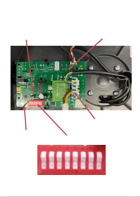
The unit is supplied already fitted with a 1 x metre
long, three core cable as standard. Brown = Live.
Blue = Neutral. Green / Yellow = Earth. This unit
should be protected by using a 3amp inline fuse.
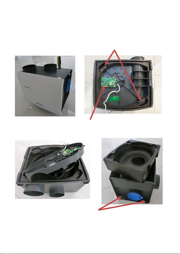
Before function testing the fan, ensure the impeller
runs freely. Also refer to page 12, Pairing Remote
Controls. Function testing should be carried out by
switching the fan on for a short time. When the fan is
running, checks should be carried out for: impeller
rotation direction, undue noise or vibration and
power consumption. Immediately switch off the fan
should any problems be found, and contact Airflow
Developments Ltd. Fan motors used are suitable for
continuous running and have a rated duty type S1
(motor is suitable to this duty type and rating at which
the fan may be operated for an unlimited period).
Page 7 of 27

PCB Main Features
Page 8 of 27
LED Red / Green
Cable to RF
Receiver
Push button
DIP Switches
Mains power in
230V –50 –1Ph
Picture of dipswitchPicture of dipswitch

Mechanical Installation
Mechanical installation should only be carried out
by a competent person. Fans are supplied ready for
installation. Care should be taken when removing
the fan from its packaging. Correct lifting
techniques / apparatus should be used where
necessary. Units should be inspected for any
damage. If the Unit is found to be damaged, it
should be returned to the supplier immediately.
Units should be installed to a sufficiently solid
structure giving adequate support. Fixings suitable
for the mounting surface should be used. Airflow
Developments Rubber mount part number
90001294 (set of four) can be used to help protect
against mechanical noise transmission into the
mounting surface.
Units are mounted by using the four moulded slots
in the base of the extract duct connection box. See
fig D page 10.
Units can be mounted at any angle or position.
When mounting ensure there is no distortion to the
fan case or duct connection box.
Page 9 of 27

Mechanical Installation contd.
B
A
Page 10 of 27
C
D
Mounting Slots
Fan Tray Lifting Points
PCB

Duct Connection
This unit has three 124mm and one 124/160mm
diameter ports moulded on the extract duct
connection box. Three ports are sealed off with
blanking plates. The 124/160mm diameter port
offers a choice of duct size, this is to help duct
system pressure on higher airflows. Care should be
taken when removing the 124mm diameter port and
membrane to ensure no excess force is used which
could cause irreputable damage. See page 3.
Failure to remove the whole membrane could cause
excess system pressure and noise.
Air is expelled to outside from the unit by the 124mm
diameter open port in the fan mounting case. See
page 3. If the ducting from this port is installed
vertically a condensation trap should be fitted
(Airflow part number: 90001242).
125mm diameter ridged ducting, or a ridged duct
with at least 90% free surface area of 125mm
diameter duct should be used. This isto keep system
pressures to a minimum.
Page 11 of 27

Duct Connection contd.
Pairing Remote Controls
Page 12 of 27
Two RF remote controllers are available, a basic
controller (Part No: 90001489) and a controller with
built in CO2sensor (Part No: 90001490). Each
MEV WH4H unit must have at least one RF
Controller. Each unit can be paired with up to 20 x
controllers. A mixture of controllers can be used to
suit application.
Before pairing the unit should be isolated from the
electric supply for a minimum of 5 x seconds. The
LED on the controller will flash red then green.
Final connections can be made with a short length
of flexible ducting (Airflow part number: 52641009)
and the correct sealing clamps (Airflow part
number: 51849403). Theuse of excessiveamounts
of flexible ducting will result in high system
pressures and a noisy system. Ridged duct
connections should be sealed with a non-hardening
sealant (Airflow part number: 90000356).

Paring Remote Controls Cont.
When electric power to the unit is re-installed the
LED red / green on the PCB (See page 8) will flash
red and green then remain green for 3 x minutes. In
this time the RF controllers can be paired to the unit.
Basic Controller (90001489) Pariing
Note: Ensure controller has a battery fitted.
Pairing the controller(s) to one unit is done by
pressing the “1”and “auto” buttons, on the controller
simultaneously, while the unit PCB LED is green,
until the LED on the controller flashes red –green -
red. To show the paring is complete the LED on the
unit PCB and the LED on the controller will flash
green ten times. Also, the unit will run for a short
period at a higher speed.
Alternative pairing procedure. Leave the unit
connected to the electric supply. Remove the white
top cover from the unit. Briefly press the push button
on the units PCB. See page 8.
Page 13 of 27

Paring Remote Controls Cont.
CAUTION!! Risk of Electric Shock. Do not touch
other parts of the PCB as they remain live. After
which the LED will remain green for 3 x minutes. In
this time the controller can be paired to the unit by
pressing the “1” and “auto” buttons on the controller
as previously stated.
Pairing controller(s) to Several Units. To do this
follow the alternative pairing procedure except
push buttons “2” and “auto” on the controller
simultaneously for 3 x seconds.
To replace a basic controller, all controllers must
be un-paired to the units PCB, then any
controller(s) needed must be re-paired to the units
PCB.
CO2Controller (90001490) Pairing
Note: Ensure controller is connected to 230V –
50Hz single phase power supply.
Before pairing the unit should be isolated from the
electric supply for a minimum of 5 x seconds.
Page 14 of 27

Paring Remote Controls Cont.
When electric power to the unit is re-installed the
LED red / green on the PCB (See page 8) will flash
red and green then remain green for 3 x minutes. In
this time the RF controllers can be paired to the
unit. Briefly press the control button on the CO2
controller once. A red LED will flash on the
controller. Then press the control button for a
further 7 x seconds until a blue LED lights up and
the status LED flashes alternately red and green.
When pairing has been successful the LED on the
unit and controller will flash ten times and the fan
speed will increase for a short while. Paring
additional CO2controllers is carried out in the same
way.
Un-Paring Controllers to a unit. Remove the
white top cover from the unit. Press the push button
on the units PCB. (See page 8) for 15 x seconds
until the LED is simultaneously red and green
(orange). Release the push button, the LED will
flash red–green–red. All connections to controllers
are now cut. The airflow requirements of a dwelling
should be
Page 15 of 27

Fan Performance Settings
calculated and conform to Building Regulations
Part F,Volume1.
This unit has two airflow performance curves to
choose from. Each performance curve is broken
down into three bands, low, medium, and high.
Each band has a number of fan speeds to choose
from. All of which can be set by adjusting the dip-
switch settings. The dipswitch can be found on the
units PCB, which is under the unit’s white, top
protective cover held on by “D” shaped tabs. (See
fig.A and B on page 10). Choice of appropriate
band speed the fan runs at is by using the RF
controllers (Airflow part numbers:900001489 and
90001490.
Note: When controls are set to “auto” the unit will
run on the low fan speed range until humidity or
CO² is sensed. When this happens, the unit will
automatically increase the fan speed to the
medium range then if needed to the high range.
Dipswitch 8 controls the overrun time when the
unit is sensing humidity. When in the OFF position
= 15 minutes. When in the ON position = 30
minutes.
Page 16 of 27

Fan Performance Settings Cont.
Page 17 of 27
Table A

Fan Performance Settings Cont.
Table B
Page 18 of 27

Flow / Pressure Graph A
Page 19 of 27

Flow / Pressure Graph B
Page 20 of 27
This manual suits for next models
1
Table of contents
Other Airflow Accessories manuals
Popular Accessories manuals by other brands

Royal Catering
Royal Catering RCCC-160ST user manual

Meade
Meade Zero Image-Shift operating instructions

SOLAC
SOLAC CT8607 manual

Ningbo Pdlux Electronic Technology CO.,Ltd
Ningbo Pdlux Electronic Technology CO.,Ltd PD-V19 instructions

Meister
Meister RCS-20GS-A+RC10 operating instructions

PCB
PCB TORKDISC 5309D-02A Installation and operating manual