
8Airginners Manual version 1.0 2022
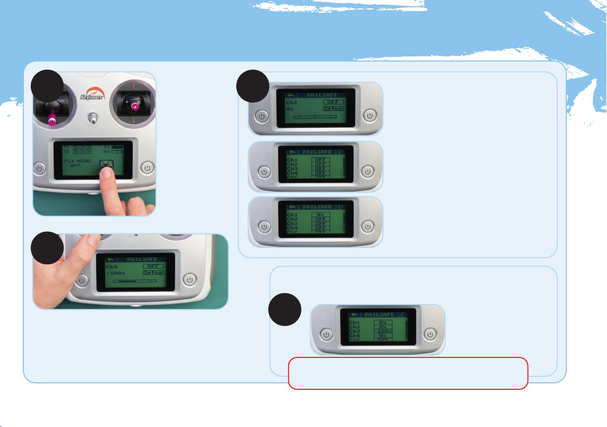
Seing up the failsafe
STEP 1 STEP 2
STEP 3
STEP 4
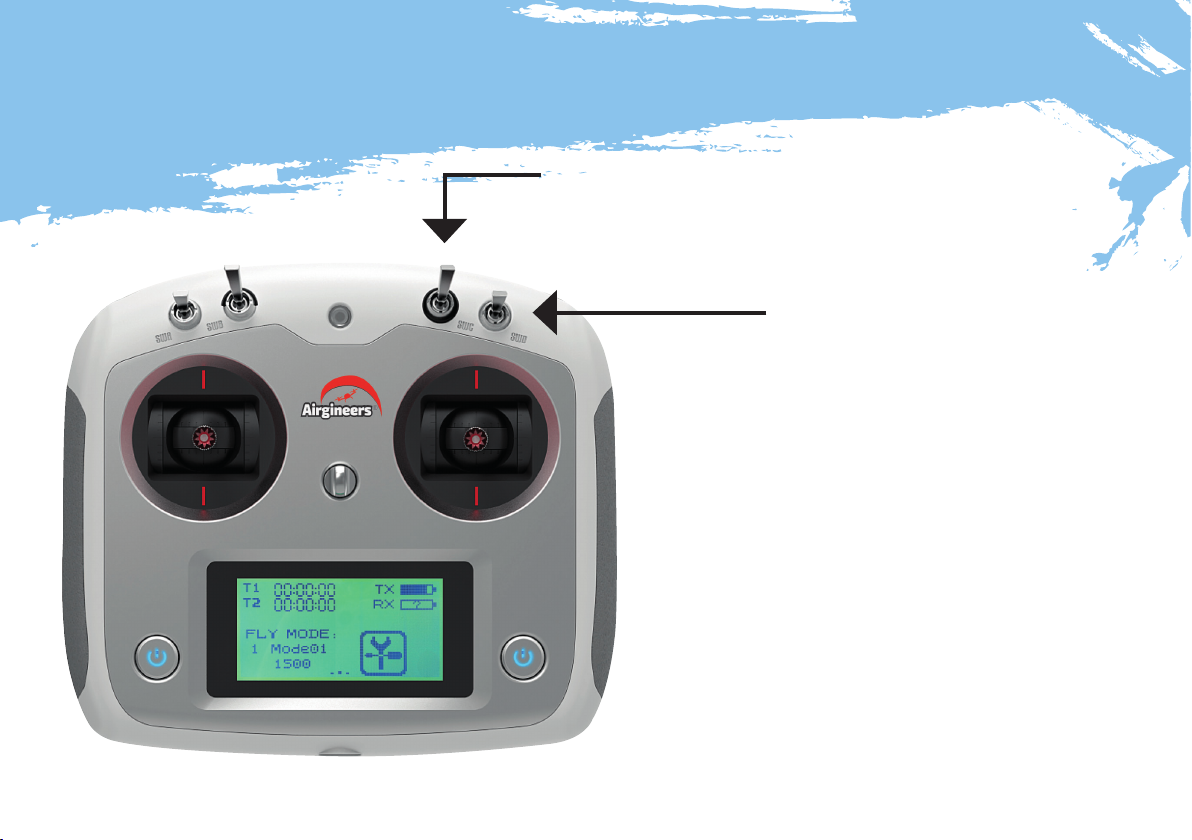
Turn on the
transmitter, by
pressing the two
ON/OFF buttons
located either
side of the screen.
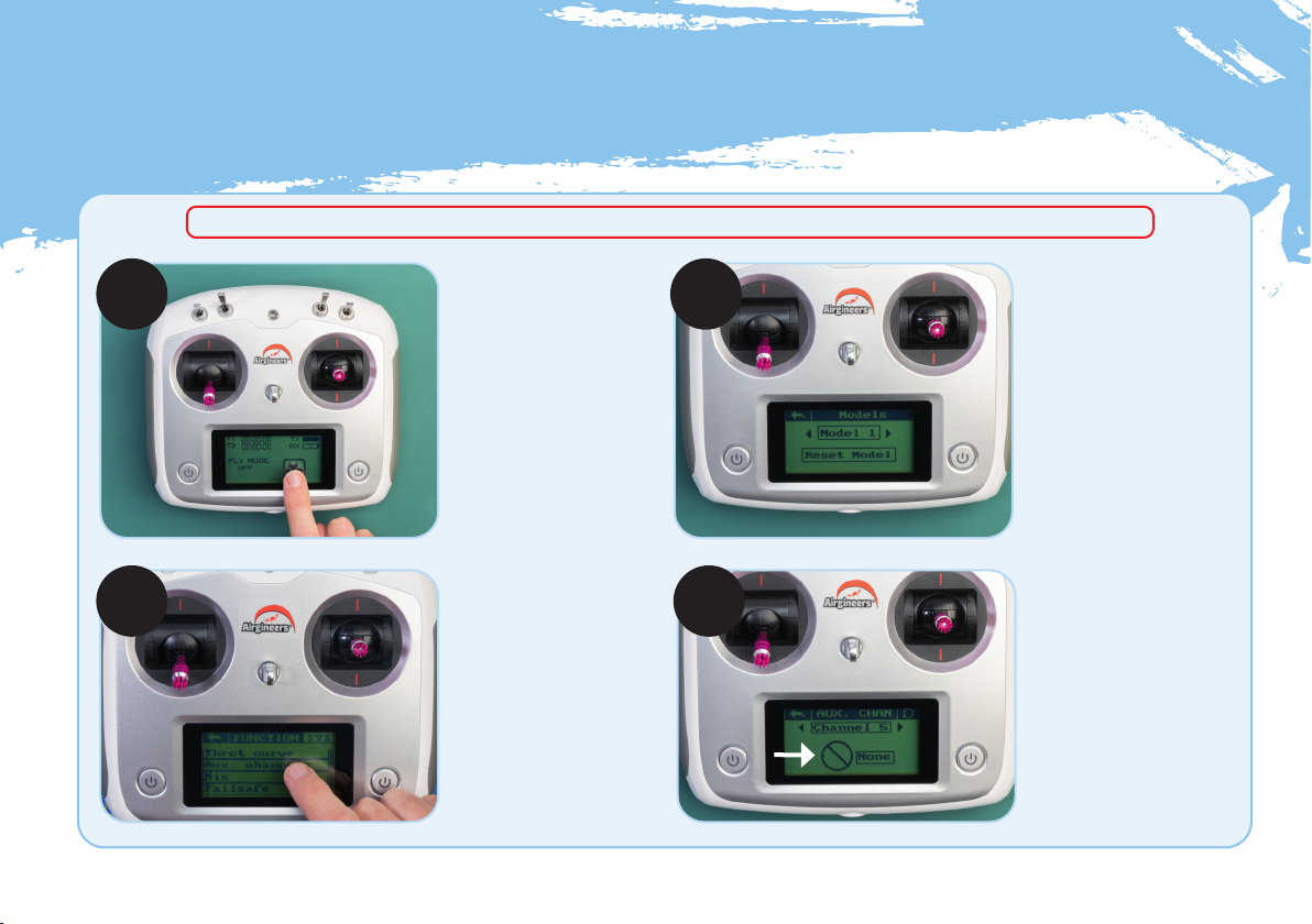
Press the spanner/
screwdriver icon
on the screen, then
select FUNCTION.
Scroll down to the
bottom and select
Failsafe.
Select FAILSAFE for Ch1, by pressing OFF.
On the next screen select ON.
NOTE: Ch1 controls the left/right movement
of the right-hand control stick. You can test
this by moving the control stick left and right,
the movement should be indicated in the bar
across the bottom of the screen as the
stick moves.
Make sure that the stick is in the neutral (centre)
position and press SETUP. Then use the back
arrow to go back to the Failsafe -channel select
menu. You should now see that Ch1 is set to 0%.
Repeat the setup procedure for Ch2 and Ch4.
NOTE: Ch2 controls the forward/backward
movement on the right-hand control stick. Ch4
controls the left/right movement of the left-
hand control stick.
Select FAILSAFE for Ch3, select ON.
NOTE: Ch3 controls the up/down (throttle) movement
of the left-hand control stick.
Make sure the left-hand control stick is all the way down.
Press SETUP (-100% shows on screen).
Use the back arrow to go back to the Failsafe channel select menu. You
should now see that Ch3 is set to -100% and Ch1, 2 and 4 are set to 0%.
Failsafe is now set up. Use the back arrow to return to the main menu.
IMPORTANT: Setting the Failsafe mode allows the drone to stop
ying and drop to the ground in the event of loss of transmission.


 user manual")