airleader Master-4 User manual

WF STEUERUNGSTECHNIK
Operation manual for Compressor-Management
AIRLEADER Master-4
Zeppelinstr. 7-9, 75446 WIERNSHEIM
Tel. +49 7044 911100, Fax +497044 5717
www.airleader.de info@airleader.de
5460 33rd Street SE
Grand Rapids, MI 49512
Phone 616 828-0716
www.airleader.us info@airleader.us

SUMMARIES
AIRLEADER Master MODUL
Page 2 Summaries
Page 3 Almost the best strategy to sava energy // Program version serial number
Page 4 Funvtional description
Page 5 Main Menu, System information, Symbol Legend
VARIABLE SPEED COMPRESSOR
Page 6 Control and interpretation of regulated compressors
Page 7 Configuration of regulation range and regulation buffer
Page 8 Minimum flow rate and remote pressure supply
Page 9 Station with 2 variable speed compressors
PROGRAMMING COMPRESSOR CONTROL
Page 10 Programming variable speed compressors
Page 11 FU-Control for variable speed compressos
Page 12 Programming load / unload compressors
Page 13 Programming pressure, rank profiles and system parameter
Page 14 Control Parameter
Page 15 Programming of analog inputs of Master Module
Page 16 Programming analog and digital inputs of connection modules (17-24)
REAL TIME CLOCK
Page 17 Programming real time clock
Page 18 Clock programming notes
STATUS DATA and COMMISIONING
Page 19 Status data of compressors and connection modules
Page 20 IP-address and network settings, // Global settings
Page 21 Alarm messages // Data Manager // Diagram
Page 22 Commisioning and switching functions
2

AIRLEADER combines compressors of different sizes to an optimum unit
For program version, serial number and network touch >Status >Control and SD Card
Almost the best strategy to save energy
Pmax
Pmin
25
25
25
13
7
m³/min
Load
Energy
- only program the compressor capacities
- set the common pressure switch points
- mount the pressure transducer
- connect the cables
The compressors will be controlled by the real air consumption
Within only 1 pressure difference for all compressors
Un-load saving
Load energy saving
3

FUNCTIONAL DESCRIPTION
4
AIRLEADER combines compressors of different sizes
to an optimum unit which automatically adapts to the production based on the current compressed air consumption. It is
made sure that it is always the most efficient compressor combination which generates the compressed air necessary for
production, independent of the manufacturer and the performance. The system pressure remains within the smallest
limits. It is seen that the costs are kept as low as possible. The compressor performances and a common pressure
difference are programmed in for all the compressors. Based on this information, AIRLEADER permanently calculates the
current compressed air consumption and the volume of the compressed air system. The self-learning 8-fold calculation
depth makes it possible to adapt the compressors to the changes in consumption in a dynamic way.
Automatic compressor change as per compressed air consumption
If all the compressors are on the same rank, they are working fully automatically and based on real air consumption. The
priority of the compressors is adapted to the production process in real time with a useful hysterisis calculation. It is always
the compressor combination with the lowest cycle rates which is running and thus with the lowest idle times. Big
compressors are only running when needed. The smaller compressors are running under load instead of idling the big
compressors. The compressors auto-regulate the motor start limitations.
The status of the compressors is constantly monitored.
If a running compressor displays a malfunction within the pressure range or is switched off for service, its performance is
taken over by other compressors. If several compressors are needed to do this, addition is made time-delayed. Load and
total running times are stored for the individual compressors. The operating hours are deleted, if required.
Connecting of compressors
is effected using the connecting moduls this being installed in the electrical housing of the compressor on the DIN-rail. The
connection to the Master control is made over the industry us RS 485 bus. The operating voltage of 24 volts AC/DC can
be attached to the tension supply of the compressor. If a power supply of 24V AC or DC is available from the
compressor electric.
Compressor fault
If a compressor goes on fault the display shows a symbolic cross. On fault of reported compressor the performance gets
the compressed air consumption the most favorable compressors combination replaces through this one. The fault report
for the compressors is activated at the AIRLEADER an common fault signal.
Faults from the connection modules will be given out over the digital output „General fault of external equipment.
Compressor motor running
If these inputs get connected, AIRLEADER receives the motor running time. The total hours are also stored as the load
hours. The advertisement of the hours can be retrieved over the display. The running time compensation provides equally
running times of compressors with same capacity.
Compressor ready input
These input must be connected so that compressor management AIRLEADER recognizes the readiness of the
compressors. If these input don't get connected, the compressor cannot be in operation. A fault signal isn't activated.
der Kompressor nicht bereit und kann nicht angewählt werden. Eine Störmeldung wird nicht aktiviert.
If the fault input is not connected
and one of the compressors stops due to a malfunction, the display will show a wrong compressed air consumption (too
high = by the value of the faulty compressor). For this reason it is advisable to connect the malfunction signal inputs, so
that the compressed air consumption is always shown correctly and the capacity is also corrected and immediately after
reaching the P min.

Main Menu, System information, Symbol Legend
5
Touch „Program“ to enter the control settings
Status and Systeminformation -Touch „Status“-
Kompressor Status Symbole

Control and interpretation of regulated compressors
6
The various speed regulated compressor is integrated actively
The VSD compressor send the information about the motor speed over an analog output to AIRLEADER. This parameter must be
programmed to the minimal and maximum capacity of the delivered compressed air. The analog output of the VSD
compressor have to be 4-20 mA. VSD Compressors with an analog output of 0-10 VDC must be changed from 0-10 VDC with a re-
ceiving multicoupler to 4-20 mA.
The pressure Setpoint of the VSD compressor must be centrically programmed between the AIRLEADER switch points.
The right combination of compressor capacities
together with speed regulated and normal compressors with a firm performance is decisive for good results in regulation. Is the various
speed regulated compressor the smallest in combination with only bigger compressors there are only small section regulated by the vari-
ous speed compressor. Big mechanical hurdle cannot be regulated directly.
Example of the right interpretation of the performances:
4 - 20 mA
4536271890
2,5-16 m³/min 10 m³/min 20 m³/min
0
9
18
27
36
45
4536271890
0
9
18
27
36
45
m³/min m³/min
Pmin
Pmax
Pmin
Pmax
2,5-16 m³/min 20 m³/min
20 m³/min
Correct combination Incorrect combination

Configuration of regulation range and regulation buffer
7
Examble with a VSD Compresor with a regaulation range between 2,5 - 16 m³/min -
The free definable regulation range max
switches load/unload compressors ON and OFF within the pressure settings of AIRLEADER. The regulation limits are defined with the
regulation range max and the regulation buffer. Is the regulation range max adjusted lower than the maximum capacity of the VSD, the
regulation range max and the regulation buffer will be activated.
Setting the "regulation range max"
Examble: the regulation range max will be programmed to 15 m of m³/min. If than the compressed air consumption is going higher
than 15 m³/min a time flexible trend calculation watches the compressed air consumption and switches another compressor on (10 m
³/min like example). Within the pressure switch points of AIRLEADER. If the speed's regulated compressor reaches the regulation
range max the second time together with the 10 m ³/min compressor at 25 m ³/min air consumption again, the 10 m ²/min compres-
sor will be replaced with the 20 m ³/min compressor directly.
The 10 m ³/min compressor will be switched on if air consumption reaches the regulation range max of the regulated compressor at 35
m of ³/min together with the 20 m ³/min compressor.
Setting the "regulation buffer"
Examble: the regulation buffer will be programmed to 1,5 m³/min. If the compressed air consumption is getting lower and the regulated
compressor comes to the point "lower than 15 m³/min" together with the 10 and 20 m³/min compressor the regulation buffer of 1,5 m³/
min will be activated. The air consumption get again 1,5 m³/min lower a time flexible trend calculation stops the 10 m³/min compressor
inside the adjusted pressure switch points at the AIRLEADER. The VSD compressor regualtes to the capacity of 13,5 m³/min.
Correct setting of regulation buffer incorrect setting of regulation buffer
Regulation range max = 15,0 m³/min Regulation range max = 15,0 m³/min
Regulation buffer = -1,5 m³/min Regulation buffer = -3,5 m³/min
Min compressor capacity = -2,5 m³/min Min compressor capacity = -2,5 m³/min
Control sum = 11,0 m³/min Control sum = 9,0 m³/min
Note:
- the regulation range max will be activ if the control sum is smaller than the capacity of the load/unload compressor
- the regualtion buffer is active if the controll sum is higher than the capacity of the load/unload compressor
The VSD compressor will be run in his best specific range.
regulation range
0
6,6
Switch off with regulation buffer
4536271890
2,5-16 m³/min
m³/min
Pmin
Pmax
max
18
27
36
09182736
max
10 m³/min 20 m³/min
max
buffer
max max max
buffer
buffer

15
m³/min
Pmin
Regulation range
max
min
minimized
capacity
examble 15 m³/minexamble 4,5 m³/min
0
Pmin
16128
4
0
2,5-16 m³/min
0
4
8
12
Pmin
Pmax
Minimum flow rate and remote pressure supply
8
Settings „minimum flow rate“ of variable speed compressor
By setting the minimum capacity in the menu of the speed regulated compressor
can be determined whether or below the minimum delivery amount of a normal
compressor compressor in load / idle to run mode.
Setting the minimum flow rate of 0 m / min causes:
The speed controlled compressor is running in start / stop operation as long as the
consumption of compressed air is from 0 to 2.5 m³ / min.
Setting the minimum flow rate of 2.5 m³ / min causes:
Below 2.5 m³/min compressed air consumption a normall compressor is running in
a load / unload mode. The downshift is receding in consumption with a hysteresis
This mode is only economic if the air station with a small compressor as 2.5 to 4 m /
min is installed in addition
Pressure differences caused by dryers and filters
cause may be between the pressure transmitter
of the controlled compressor, and the master
control rule up to 0.4 bar difference.
A precise control of pressure within very close
limits is not possible. The pressure difference at
the higher level control must be expanded by
the pressure value can be set. This results in a
pressure differential of 0.7 bar.
(More than at a station without a regulated com-
pressor)
With the remote control actual pressure value
ensure that the regulated compressor can be operated in conjunction with the master control in a narrow pressure limit.
The analog output of the connection module, deliver the current actual pressure of AIRLEADER via 4-20 mA.
If the compressor pressure transmitter has an different range, than the output has to be adjusted accordingly.
Examble:
AIRLEADER 0-16 bar = 4-20 mA
Compressor 1-20 bar = 4-20 mA or Compressor -1-15 bar = 4-20 mA
An offset value setting for remote actual pressure
can be programmed via the menu of regulated compressor to the pressure setpoint of the controlled compressor to adjust the pressure
difference.
This is especially important when more than 1 controlled compressor is installed in the compressed air network and the analog values
do not match the individual compressors
Remote pressure supply through analog output at the RS-485 connection module
0,4 bar
Capacity of regulated compressor

Station with 2 variable speed compressors
9
In a station with 2 regulated compressors
the pressure transducer of regulated compressors in the same place as the pressure transmitter of the AIRLEADER feel, because differ-
ences in pressure of compressed air dryers and filters, the control behavior can influence each other greatly.
The configuration is described on page 4.
Settings „regulation range max“ und regulation buffer
examble 1: 2 variable speed compressors with same capacity
examble 2: 2 variable speed compressors with different capacities
In examble 2
- if compressor 1 reach the regualation range max - it changes to compressor 2
- if compressor 2 reach the regualation range max - compressor 1 start again
- if both compressors reach the regulation gange max - one of th load / unload compressor will be started
- the controller decides, dependent of air consumption tha one of the regulated compressor can be switched off
The regulation range max
ensure that regulated compressors are always in the correct specific area. If an varaiable speed compressor delivers more air than the
setting of the regulation range max, the control started a flexible trend calculation to start the next load/unload compressor. Dependent of
the compressed air consumption.
compressor compressor type m³/min Regulation range max Regulation buffer Min. flow rate
1 Variable speed 5-30 28 m³/min 5 m³/min 0
2 Variable speed 5-30 28 m³/min 5 m³/min 0
3 load / unload 15 - - -
4 load / unload 25 - - -
compressor compressor type m³/min Regulation range max Regulation buffer Min. flow rate
1 Variable speed 1,5-10 9 m³/min 1,5 m³/min 0
2 Variable speed 5-20 18 m³/min 4 m³/min 0
3 load / unload 15 - - -
4 load / unload 25 - - -
max max max max max
regul. buffer
regul. buffer
Regulation range Downshift with regulation buffer
5-30 m³/min 5-30 m³/min
25 m³/min
15 m³/min
max max
regul. buffer
max
regul. buffer

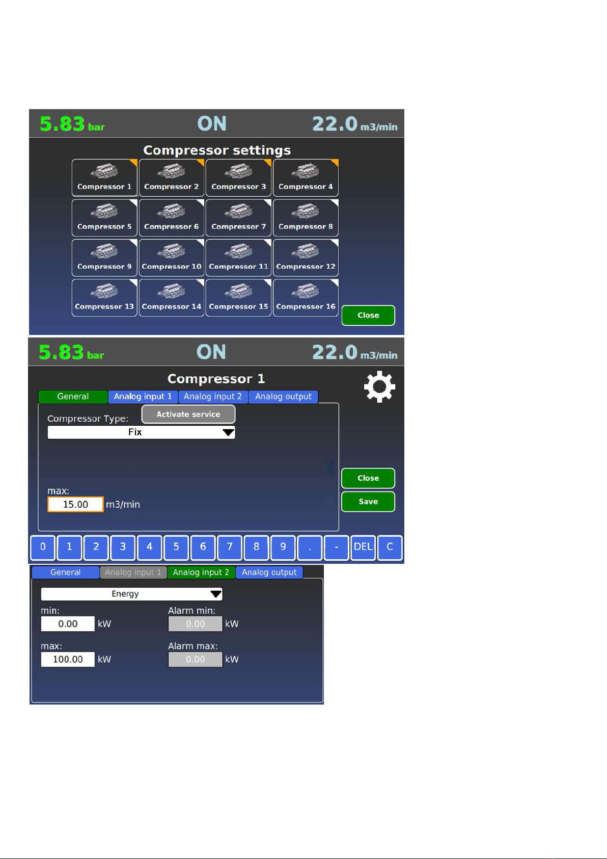
Programming variable speed compressors
10
Touch >Settings >compressor
than
Touch > on compressor symbol
> set min capacity
> set max capacity
> set Imax
> set Imin
> set regulation range max
> set regulation buffer
> compressor min air flow
Attention:
Activate servise for maintenance
the signal "Ready" is deactivated and
the compressor goes into idle when it
is running on load
Install Senor on Analog Input 2
Touch on Analog input 2
> select type of installed sensor
> set min range of sensor at 4 mA
> set max range of sensor at 20 mA
> set min Alarm point
> set max Alarm point
Following sensors are possible:
> Amperé
> Universal sensor
> Power (kW)
>Temperatur
> Bearing monitor
If the sensor value is out of the Alarm
setpoints, you will get an alarm on the
Web-Server Visualisation
Touch on Analog output „AO“
> set min and max range of the
compressor pressure sensor
at 4 mA and 20 mA
> set max range of sensor at 20 mA
> set pressure offset if it is neccessary
Don´t select !Average value output
If average value output is selected
the analog output signal ist the
average between Pmin and Pmax of
Airleader pressure setting
Fault input selection
Standart is C-NC
If neccessary change to
C-NO

FU-Control for variable speed compressors
11
Setting the offset correction
> maximum limit,
> minimum limit,
> Sampling frequency with
FU-Control,
controls the frequency of possible
corrections
> offset increment,
Change in pressure values
> maximum offset,
Maximum change in print offset
FU-Control: (Switch on via the menu of the control parameters)
This function can be activated when several regulated compressors are working in the compressed air network. The condition here is
that the controlled compressors are controlled via the analog output of the compressor module according to the network pressure.
(ACTUAL pressure value) As a result, the compressors and the Airleader have the same pressure. Is one of the regulated
compressors running in the uneconomic area, -e.g. at 100% or 30% for a longer period of time, the actual pressure value is changed
slightly by 0.05 bar until the compressors are running in the good range again. Maximum adjustment 0.2 bar.
Diagram with – and without FU-Control
FU-Control switched „ON“
Net pressure
Programming load / unload compressors
12
Touch >Settings >compressor
than
Touch > on compressor symbol
> set capacity
Touch on Analog input 1 „Ai-1“
> set type of sensor
> set min range of sensor at 4 mA
> set max range of sensor at 20 mA
> set min Alarm point
> set max Alarm point
Following sensors are possible:
> Amperé
> Power (kW)
Install Senor on Analog Input 2
Touch on Analog input 2
> select type of installed sensor
> set min range of sensor at 4 mA
> set max range of sensor at 20 mA
> set min Alarm point
> set max Alarm point
Following sensors are possible:
> Universal sensor
> Temperatur
> Bearing monitor
If the sensor value is out of the Alarm
setpoints, you will get an alarm on the
Web-Server Visualisation
If current measuremet is selected
> set min range of sensor at 4 mA
> set max range of sensor at 20 mA
If energy measuremet is selected
> set min range of kW meter at 4 mA
> set max range of kW meter at 20 mA
OPTION: Vibration sensor
Bearing monitor if Alarm and Service
management is installed

Pressure and rank profiles + system parameter
13
RANK PROFILES
Menu „compressor rank profile
“
Examble: Follwing compressors shall
be controlled
- compressor 1+2 with 20,0 m³/min
- compressor 3+4 with 18,0 m³/min
- compressor 5+6 with 12,5 m³/min
Special request
> Compressor 1 + 6 is connected to
an heat recovery
> Compressor 3 as standby only
Recommended programming
compressor 1+6 rank 1
compressor 2+4+5 rank 2
compressor 3 rank 3
PRESSURE PROFILE
Menu „pressure switch points“.
4 different pressure profile can be
programmed. The pressure profi-
le 2, 3, and 4 can be selected
over:
real time clock
digital input 1, 2 and 3
New function: "set compressors to manual mode"
If -0.0 bar- is entered in the two fields "lower Pmin" and "higher Pmax", this function is not active.
If the pressure in the "lower Pmin" field is entered as 0.5 bar, Airleader switches the compressors to manual operation,
when this value is undershot. (Control compressor's with their own control)
If the pressure in the "higher Pmax" field is entered as 0.5 bar, Airleader switches the compressors to manual operation if this va-
lue is exceeded. (Control compressor's their own control)
If the "automated manual mode" function is active, The "MAN" key switch has to be switched to "1" for a few seconds.
Then switch back to "0" to activate automatic operation via Airleader,
Compressors in the rank stage 1will be controlled denpendent on the actual air consumption.
If this is not enough, the compressors of the rank 2 and helps rank 1
ATTENTION: Only compressor on the same rank stage will be controlled automaically by the dependent airconsumption.
Time cycle compressor order
In this menu equal hour for compressors
with the same capacity can be pro-
grammed.

Control system parameter:
changing of this settings only with
coordination by the manufacturer.
Delay time start:
If Airleader is activated via the "Start key switch or real time clock" and the network pressure is lower than the settings of
Pmin value, a compressor is switched on immediately. All other compressors will be switched on individually after the programmed
time. Programmed rank profiles are taken into account. order from large to small.
Security zone below:
If the demand for compressed air suddenly increases and the pressure drops below Pmin, further compressors switch on after
calculating an additional demand. Or small compressors are replaced by compressors with greater capacity.
Security zone high:
If the demand for compressed air drops suddenly down and the pressure rises above Pmax, more compressors will be switched off
after programmed time and calculating a reduced demand.
Or larger compressors are replaced by compressors with smaller capacity.
Delay time below:
This function prevents several compressors from being started when they are not required, becaus compressors start only after
approx. 15-30 seconds producing compressed air. If a compressor was switched on in the below ssecurity zone, the next compressor
will only be switched on after the programmed time has been elapsed.
Delay time high:
If a compressor has been switched off at the high security zone, the next compressor will only be switched off after the progammend
time. Setting information: large receiver volume = longer time, small receiver volume = shorter time
FU average:
The analog output signal from the frequency inverter will be averaged with the programmed time.
The control process becomes more harmonious.
Fixed compressors if possible: (Fixed capacity compressors – if possible)
If several speed-controlled compressors are installed in the compressed air network, in combination with compressors with a fixed
output, these will be switched on as early as possible in order to increase the specific power.
The prerequisite for this is a sufficient large regulation range of variable speed compressors.
FU Control: See page 11
This function can be activated when several variable speed compressors are working in the same compressed air network.
The condition here is that the variable speed compressors get the net pressure via the analog output of the compressor module
according to the network pressure. (ACTUAL pressure value)
As a result, the compressors and the Airleader have the same pressure level.
Is one of the regulated compressors running in the uneconomic area, -e.g. at 100% or 30% for a longer period of time,
the actual pressure value is changed slightly by 0.05 bar until the compressors are running in the good range again.
Maximum adjustment 0.2 bar.
Control Parameter
14

Analog - Inputs of Master
15
ANALOG inputs on Master Module AIRLEADER Master has as standart 4 analog inputs
TO program the analog inputs > touch on the button of analog input
Anlog input „Ai1“
only for pressure transducer. The pressure transducer extend the supply of AIRLEADER and is includet. No other sensor should be
connected to the system. The pressure is displayed in the display on the left head line.
Analog input Ai2, Ai3, und Ai4
can be used for following sensors:
> Dew point
> Temperature
> Flow
> Extra pressure
> Current measuring
> Energy measuring
For each analog input is an digital output available for alarm signals
Programming of alarm signals:
> for minimum signal
> for maximum signal
can be programmed for each connected analog sensor. The measurements of these sensors are displayed permanently.
.
Parameter setting of analog inputs for examble:
> 4 mA upper data (Tmin)
> 20 mA lower data (Tmax)
The window for the alarm specification is programmable vacant within the sensor values.

Analog and digital-inputs of connection modules
16
ANALOG and DIGITAL inputs
Up to 8 connection modules can be
connected for external analog sensors
and digital potential free contacts of
dryers, condensate drains etc. The
digital signals can be used as fault or
running signals.
The modules get the number 17-24.
Address settings by the 8 DIP
switches
Every connection module
has following out and inputs:
> 2 analog inputs for analog sensors
with 4-20 mA Signal
> 3 digital inputs for fault an running
signal of external equipment
> 1 analog output 4-20 mA over the
range of the connected net pressure
transducer
> 2 digital outputs (C-NO-NC 230VAC
2A) for signal output of connected
Analog sensors (alarm set points)
Possible sensors for analog inputs:
> Dewpoint
> Temperature
> Extra pressure
> Flow
> Current measurement
> Energy measurement
> Vibration for bearings
Analog output at the connection
module It is the actual pressure signal
from the AIRLEADER as long as the
average output is in No (N) position. .
(See page 6)
Note: If average value output is
programmed to „Y“ it belongs an
another connection module for the
pressure signal of the control.
The digital inputs S - M - B
Can be selected as:
> fault signal—with alarm message
> run signal for external equipment
Running hour will be displayed in
the Web-Server visualisation
On all connection modules (up to 8)
can be connected –up to
> 24 digital messages
> 16 analog inputs for sensors
Digital output R1 and R2 on the connection module
If the digital output function is activated on a module (17-24), the timer outputs are
connected synchronously with those on the master. Timer output R1 on the master
corresponds to digital output 7. R2 on master digital output 8

PROGRAMMING REAL TIME CLOCK
17
Note down all attitudes
for all program switching functions so
that no being missing programming
arise.
Key switch „CLOCK“
The real time clock is only activated if
the the key switch is in position „1“
Up to 16 switching points can be
programmed in the menu clock
Set date and time
Touch on each field and set the date and
Time of the real time clock.
Examble:
1. Monday to Friday from 6:00-22:00h
> Control system ON
> Pressure profil 1
> Rank profil 1
> Digital output R1 ON for dryer
2. Monday to Friday from 22:00-24:00 h
> Lower pressure with pressure profil 2
and rank profil 2
> At the same time switching to a
smaller dryer switched by digital
output R2
3. At 00:00 h
The compressed air equipment can be
switched OFF by the real time clock
Key switch „CLOCK“
deactivated the clock relay functions. If
the position is ín position „0“.
The compressors management is
switching the compressors to the
> 1st pressure profile and
> 1st rank profile
That is programmed in the basic menu
over the data of the 1st pressure and
1st rank profile.
The clock relay permits following time
controlled functions
> Switchung compressors ON/OFF
> 4 pressure profiles, > 4 rank profiles,
> 2 digital outputs for relays to switch
ON/OFF additional equipment like
(Dryer, ball valves, etc.)
The dates for the 2nd, 3rd. and 4th
pressure profil and rank profil must be
configurated in the main menu

CLOCK - PROGRAMMING - NOTES
18
SP=switching point LS=Management Leadsystem digital output =R1 digital output t= R2
Compressor chanels
Nr. 1 2 3 4 5 6 7 8
Name
Nr. 9 10 11 12 13 14 15 16
Name
Pressure profile = PP
Nr. P min P max P Alarm
1 bar bar bar
2 bar bar bar
3 bar bar bar
4 bar bar bar
Compressor rank profile = RP
Kompr. 1 2 3 4 5 6 7 8
1.RF
2.RF
3.RF
4.RF
Clock relay switching times and functions
SP Day of the week Time LS PP RP R1 R2
1 M T M T F S S
2 M T M T F S S
3 M T M T F S S
4 M T M T F S S
5 M T M T F S S
6 M T M T F S S
7 M T M T F S S
8 M T M T F S S
9 M T M T F S S
10 M T M T F S S
11 M T M T F S S
12 M T M T F S S
13 M T M T F S S
14 M T M T F S S
15 M T M T F S S
16 M T M T F S S

STATUS DATA
19
Touch on Status to see the status
of all connected modules an sensors
Status of compressor modules
(MK) No. 1-16
and extra connected modules
(AM) No. 17-24
See the status of:
> relay 1
> relay 2
> analog input 1 Ai-1 in mA and selected
sensor data
> analog input 2 Ai-2 in mA and selected
sensor data
Condition of the sensor values
By selecting the sensor function, all
sensor values connected to the
controller are displayed by category.
The connection location is also
displayed.
e.g.
- MM AE1 analog input on the master
- AM 17 AE1 stands for
Analog module 17
Analog input 1 AE1 sensor data

IP-address settings:
Touch: > Program > Network
> set IP-address
> set Subnet Mask
> set Standart Gateway
Integrated Airleader COM server
can control up to 10 compressor stations
via COM-Server.
If compressor modules are connec-
ted via COM server the COM servers
each receive a separate IP address.
The communication speed needs to be
adjusted –see Global settings
IP-address, Network and factory settings
20
Communikation via Ethernet
The connection between AIRLEADER
and the connection modules for com-
pressors and other components can be
done via the Ethernet by using the COM
server.
The RS-485 interface AIRLEADER is
connected to a COM server.
The COM server gets an IP address that
matches the IP address range.
More COM-server can be connected to
the Ethernet with different IP addresses.
Program waiting time for slave
response
Touch: >Settings >Global
RS485 response time
set to "190 ms"
Changeable If necessary
also from 100-300 ms
This manual suits for next models
1
Table of contents
Popular Control System manuals by other brands


Rockwell Automation
Rockwell Automation Allen-Bradley CENTERLINE 2100 installation instructions

Intelligent instrumentation
Intelligent instrumentation EDAS CE manual

Cooper
Cooper Aspire RF user guide

Sea Recovery
Sea Recovery Aquamatic Quick start & troubleshooting guide

Condor
Condor 900 191 - V1.0 operating instructions

MSD Ignition
MSD Ignition 7AL-3 7230 installation instructions