Intelligent instrumentation EDAS CE User manual

EDAS CE Manual
www.edasce.com
855M536
Copyright 2001-07 by Intelligent Instrumentation Incorporated, Tucson, Arizona, U.S.A.
All rights reserved.

ii
Warranty and Repair Policy Statement
General
Seller warrants that its products furnished hereunder will, at the time of delivery, be free from defects in material and
workmanship and will conform to Seller's published specifications applicable at the time of sale. Seller's obligation or
liability to Buyer for products which do not conform to above stated warranty shall be limited to Seller, at Seller's sole
discretion, either repairing the product, replacing the product with a like or similar product, or refunding the purchase
price of the nonconforming product, provided that written notice of said nonconformance is received by Seller within the
time periods set forth below:
a. For all software products, including licensed programs, ninety (90) days from date of initial delivery to
Buyer;
b. For all hardware products (excluding batteries), including complete systems, fifteen (15) months from date
of initial delivery to Buyer, subject to the additional conditions of paragraph c) below;
c. In the event that Buyer's returned product is a Discontinued product and is not repairable for any reason,
Seller may elect to replace it with like or similar product that is, in Seller's sole judgment, the closest
equivalent to the returned product. Seller does not warrant that such replacement product will be an exact
functional replacement of the returned product.
Further, all products warranted hereunder for which Seller has received timely notice of nonconformance must be
returned FOB Seller's plant no later than thirty (30) days after the expiration of the warranty periods set forth above.
These warranties provided herein shall not apply to any products which Seller determines have been subjected, by
Buyer or others, to operating and/or environmental conditions in excess of the limits established in Seller's published
specifications or otherwise have been the subject of mishandling, misuse, neglect, improper testing, repair, alteration or
damage. THESE WARRANTIES EXTEND TO BUYER ONLY AND NOT TO BUYER'S CUSTOMERS OR USERS OF
BUYER'S PRODUCT AND ARE IN LIEU OF ALL OTHER WARRANTIES WHETHER EXPRESS, IMPLIED OR
STATUTORY INCLUDING IMPLIED WARRANTIES OF MERCHANTABILITY AND FITNESS FOR A PARTICULAR
PURPOSE. IN NO EVENT SHALL SELLER BE LIABLE FOR INCIDENTAL, SPECIAL OR CONSEQUENTIAL
DAMAGES. Seller's liability for any claim of any kind shall in no case exceed the obligation or liability specified in this
Warranty clause.
Technical Assistance and Service
Seller's warranty as herein set forth shall not be enlarged, diminished or affected by, and no obligation or liability shall
arise or grow out of, Seller's rendering of technical advice, facilities or service in connection with Buyer's order of the
goods furnished hereunder. Products returned for warranty service, but which are found to be fully functional and in
conformance with specifications may be subject to a nominal service charge and return freight charges. Periodic re-
calibration of products, if required, is the responsibility of Buyer and is not provided under this Warranty.
Online Support
Online support is available through technical support links on Intelligent Instrumentation’s 24-hour World Wide Web site
at http:// www.EDASce.com. The site contains information on Intelligent Instrumentation’s products, new
developments, announcements, application notes, application examples, and other useful information. The site and
support areas continue to grow as new products, updates, and features are added.
Email Support
Intelligent Instrumentation’s technical support can be reached via email. When sending an email message, be sure to
include complete contact information as well as a detailed description of the problem and the products being used to:

iii
Static Sensitivity
Seller ships all static-susceptible products in anti-static packages. Seller's Warranty as herein set forth shall not cover
warranty repair or replacement for products damaged by static due to Buyer's failure to use proper protective procedures
when handling, storing, or installing products.
Trademarks
FactoryView®, DASport™, EDAS®, EDAS® CE, UDAS™, Intelligent Instrumentation® are trade names and/or
trademarks of Intelligent Instrumentation®, Inc.
Other products or brand names are trademarks or registered trademarks of their respective companies.
se of Equipment
Intelligent Instrumentation Inc., assumes no responsibility for any direct, indirect or consequential loss or damages
resulting from misuse of the equipment or for improper or inadequate maintenance of the equipment or for any such
damage or loss resulting from the use of other equipment, attachments, accessories, and repairs at any time made to or
placed upon the equipment or any replacement thereof. Furthermore, Intelligent Instrumentation Inc., makes no
representations or warranties, either expressed or implied, in connection with the use of the equipment in the event it is
improperly used, repaired or maintained.
FCC Radio Frequency Interference Statement
This equipment generates and uses radio frequency energy, and may cause interference to radio or television reception.
Per FCC rules, Part 15, Subpart J, operation of this equipment is subject to the conditions that no harmful interference is
caused and that interference must be accepted that may be caused by other incidental or restricted radiation devices,
industrial, scientific or medical equipment, or from any authorized radio user.
The operator of a computing device may be required to stop operating his device upon a finding that the device is
causing harmful interference and it is in the public interest to stop operation until the interference problem has been
corrected.
The user of this equipment is responsible for any interference to radio or television reception caused by the equipment.
It is the responsibility of the user to correct such interference.
Revision History
Version Date Revision
1.0 10-30-2006 Initial Release
1.1 8-21-2007 Added EDAS-2005M-2

iv
Table of Contents
Chapter 1: Hardware and Installation ......................................... 1
1.1 Modules................................................................. 1
1.1.1 Base Unit ........................................................... 1
1.1.2 Power Supply ........................................................ 6
1.1.3 Digital I/O Module .................................................. 8
1.1.4 Analog Input Module ................................................ 12
1.1.5 Digital Input Module ............................................... 17
1.1.6 Digital Output Modules ............................................. 19
1.1.7 Analog Output Module ............................................... 21
1.1.8 Serial Module ...................................................... 23
1.1.9 Relay Output Module ................................................ 25
1.1.10 Digital Output (Triac) Module ..................................... 27
1.1.11 Quadrature Module ................................................. 29
1.2 Installation........................................................... 31
1.2.1 DIN rail Mounting ................................................. 31
1.2.2 Attaching a module to a DIN Rail ................................... 31
1.2.3 Removing Modules from a DIN Rail ................................... 32
Chapter 2: Utilities ........................................................ 34
2.1 Summary of Utilities................................................... 34
2.1.1 MonitorCE .......................................................... 35
2.1.2 LCmdSet ............................................................ 35
2.1.3 Remote Manager ..................................................... 35
2.1.4 DebugLauncher ...................................................... 35
2.1.5 TimeSync ........................................................... 35
2.1.6 SerialSocket ....................................................... 36
2.1.7 CEFlush ............................................................ 36
2.2 MonitorCE.............................................................. 37
2.2.1 Required Tools ..................................................... 37
2.2.2 Configuring the Communications Program ............................. 37
2.2.3 Starting a MonitorCE Program Session ............................... 38
2.2.4 MonitorCE Program Commands ......................................... 39
2.3 LCmdSet................................................................ 41
2.3.1 Running LCmdSet .................................................... 41
2.3.2 Making a Telnet Connection using HyperTerminal ..................... 41
2.3.3 Issuing Commands ................................................... 41
2.3.4 Set Commands ....................................................... 42
2.3.5 Show Commands ...................................................... 42
2.3.6 Change Commands .................................................... 44
2.3.7 Operational Commands ............................................... 46
2.4 Remote Manager......................................................... 47
2.4.1 WebDevice .......................................................... 47
2.4.2 Using the Remote Manager ........................................... 48
2.4.3 Remote Manager Home Page ........................................... 49
2.4.4 Application Manager ................................................ 52
2.4.5 File Manager ....................................................... 53
2.4.6 Module Manager ..................................................... 54
2.4.7 System Manager..................................................... 55
2.4.8 Security Manager ................................................... 55
2.4.9 Update Manager ..................................................... 58
2.4.10 Developer’s Guide ................................................. 58
2.5 DebugLauncher.......................................................... 59
2.5.1 Setting Up DebugLauncher ........................................... 59
2.5.2 debugworkstations.txt File Format .................................. 59
2.5.3 Changing the contents of debugworkstations ......................... 60
2.6 TimeSync............................................................... 61
2.6.1 Running TimeSync ................................................... 61
2.6.2 Command Line Arguments ............................................. 61
2.7 SerialSocket........................................................... 63
2.7.1 Configuring the COM ports .......................................... 63
2.7.2 Running the SerialSocket Utility ................................... 63

v
2.7.3 Testing SerialSocket with Hyperterminal ............................ 63
2.8 CEFlush................................................................ 65
2.8.1 Saving Registry Settings ........................................... 65
Chapter 3: Developing Custom Programs ....................................... 67
3.1 Setting up your Development Computer................................... 67
3.1.1 System Requirements ................................................ 68
3.1.2 Installing eMbedded Visual Tools ................................... 68
3.1.3 Installing the EDAS CE SDK ......................................... 68
3.1.4 Setting up Communications to the EDAS CE ........................... 69
3.2 Writing Custom Programs................................................ 76
3.2.1 Generating an EDAS CE Application .................................. 76
3.2.2 Sample Programs .................................................... 83
3.3 Loading Custom Programs................................................ 84
3.3.1 Remote File Viewer ................................................. 84
Chapter 4: CE Link API for EDAS CE .......................................... 85
4.1 Overview............................................................... 85
4.1.1 Interfacing to the I/O system ...................................... 85
4.1.2 Function Calls ..................................................... 86
4.1.3 Header Files ....................................................... 90
4.1.4 DLLs on the EDAS CE ................................................ 90
4.1.5 Registry Entries on the EDAS CE .................................... 91
4.2 CE Link API Function Descriptions...................................... 92
4.2.1 Initialization and De-initialization Calls ......................... 92
4.2.2 Unpaced Analog Input Calls ......................................... 94
4.2.3 Paced Analog Input Calls .......................................... 101
4.2.4 Analog Output ..................................................... 112
4.2.5 Digital Input and Output (Port or Byte) ........................... 114
4.2.6 Digital Input and Output (Individual Bit) ......................... 120
4.2.7 Rate Generator Functions .......................................... 130
4.2.8 Quadrature Functions .............................................. 132
4.2.9 Alarm Functions ................................................... 141
4.2.10 System and Utility Functions ..................................... 152
4.2.11 System Calibration ............................................... 156
4.2.12 Memory Management ................................................ 160
4.3 Return Error Codes for CE Link and EDAS CE API Functions.............. 163
Index ...................................................................... 179

vi
This page intentionally left blank.

Hardware and Installation 1
Chapter 1:Hardware and Installation
The EDAS CE is an open-architecture monitoring and control system based
on the Windows CE operating system. The EDAS CE features a 32-bit
processor with built-in 10/100BaseT Ethernet connectivity and a modular
I/O system. This combination makes the EDAS CE suitable for a wide range
of monitoring and control systems. The EDAS CE’s open architecture allows
the user to develop a wide range of embedded control, machine and process
monitoring applications using C/C++ or WebDevice development tools.
The built-in 10/100BaseT network, including a TCP/IP stack, enables
applications running on the EDAS CE unit to communicate with other
computers and other EDAS CE units on a network. The EDAS CE can operate
as a stand-alone system or as part of a plant-or factory-wide
monitoring/control system.
FIGURE 1.1 Typical EDAS CE System
1.1 Modules
An EDAS CE system consists of a power module, a base unit and I/O modules
as needed to meet the specific needs of the targeted application. All the
modules are plug-and-play, requiring no system configuration. Up to 12
I/O modules may be used, allowing for systems of up to 192 I/O points.
1.1.1 Base nit
Each system requires one EDAS-2000E base (processor) unit. The base unit
includes the CPU, Ethernet connectivity, and an RS-232 port. The 32-bit

Hardware and Installation 2
embedded processor runs the Windows CE 3.0 operating system, providing
real-time and multi-tasking capabilities.
FIGURE 1.2 EDAS-2000E Base Unit
The EDAS-2000E base unit includes the following features:
o32 Bit embedded processor
oWindows CE Operating System
o64 MB RAM
o64 MB CompactFlash (1GB maximum)
o1 RS-232 serial port
oOptional Non-volatile Battery RAM (128 kB)
oNetwork standards (TCP/IP, UDP, SNMP, DHCP)
oWebDevice (embedded Web server)
1.1.1.1 Application Development
Applications may be developed to execute on the EDAS CE using Microsoft’s
eMbedded Visual Tools and the eMbedded Visual C/C++ programming language.
Applications developed in C/C++ use the CE Link API for reading and
writing I/O points on the optional modules. Network and serial port
communications use the standard Windows 32 API. See Chapter 3:
Developing Custom Programs.
The EDAS CE includes a program (suprcate.exe) that runs on the EDAS CE as
a data server. A PC or other computer can open a connection and issue
commands to read and write the EDAS CE I/O points. Applications which
communicate with suprcate.exe use the Net Link API. The Net Link API
supports Visual C/C++ and Visual Basic on the Windows (98/Me/NT/2000)

Hardware and Installation 3
Platform and C on Unix platforms. See the Net Link Manual for more
information.
1.1.1.2 EDAS-2000E Base nit Specifications
All specifications are typical at 25°C unless otherwise noted.
Parameter Condition Specification
Processor AMD Elan SC400
Operating System Windows CE 3.0
DRAM Memory 64 MB
72-pin EDO SIMM 60 ns
Compact Flash 64 MB (1GB maximum)
Ethernet 10/100BaseT (RJ-45)
Serial Port 1 RS-232 (up to 115 k Baud)
Power consumption +5 VDC 1.5 A maximum
Dimensions inches
mm 4.55D x 5.9H x 3.35W
116D x 150H x 85W
Temperature Range Operating 0-60 °C
TABLE 1.1 EDAS-2000E-1 Base Unit Specifications
1.1.1.3 Ethernet
The base unit features a 10/100BaseT port. The unit has 5 red LED’s used
to display information about the Ethernet connection.
1. Link: Good link when on.
2. Collision: Collision detected when on.
3. 100BaseT: Indicates 100BaseT connection when on. When off,
connection is 10BaseT or no connection exists.
4. TX: Transmitting.
5. RX: Receiving.
1.1.1.4 Serial Port
The unit has a single serial port, COM1. The serial port can be used to
configure the unit’s network settings and real-time clock. See section
2.2 MonitorCE.
An application may read and write data to this port (COM1) using the
standard Win32 API.
Hardware and Installation 4
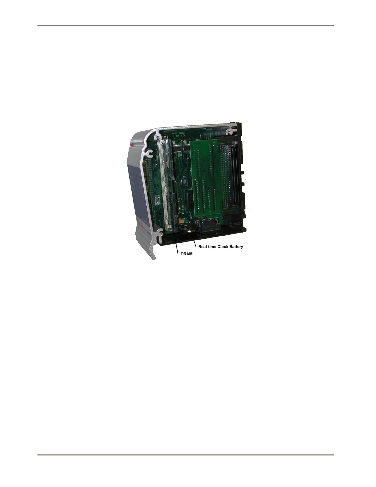
1.1.1.5 Real-Time Clock Battery
The base unit contains a 3.0 V lithium battery that powers the Real-Time
Clock when external power is absent. Battery life is approximately two
years when the unit is not powered. When the unit is on external power,
battery life is longer since the battery does not have an appreciable
power draw in this condition. To replace the battery, remove the right
hand cover of the unit.
FIGURE 1.3 Real-time Clock Battery and DRAM Access

Hardware and Installation 5
1.1.1.6 DRAM
The EDAS-2000E can use up to 64 Mbytes of DRAM. The DRAM is industry
standard 5 V, 72-pin EDO or FPM. To change the DRAM module, remove the
right hand cover of the unit.
1.1.1.7 Compact Flash
The EDAS-2000E uses standard Compact Flash memory for non-volatile
storage of the operating system and drivers. The remaining memory can be
used by the applications for non-volatile application or data storage.
The CompactFlash is accessed as part of the unit’s file system. The
CompactFlash can be replaced with a larger card to providing additional
storage capability.
1.1.1.8 Reset/Watchdog Timer
The unit has a watchdog timer that may be activated by an application.
When the watchdog timer is activated, an application must "tickle" the
timer every 2000 ms or the unit will reboot.
1.1.1.9 NV-RAM Option
The EDAS-2000E is available with an optional 128 kbytes of battery RAM.
The NV-RAM provides high speed non-volatile storage. Applications such a
fast control loops can use the NV-RAM to hold state variables, allowing
an application to recover variables after a power loss.
The NV-RAM is memory mapped to 0xA0000 to 0xBFFFF.
Hardware and Installation 6
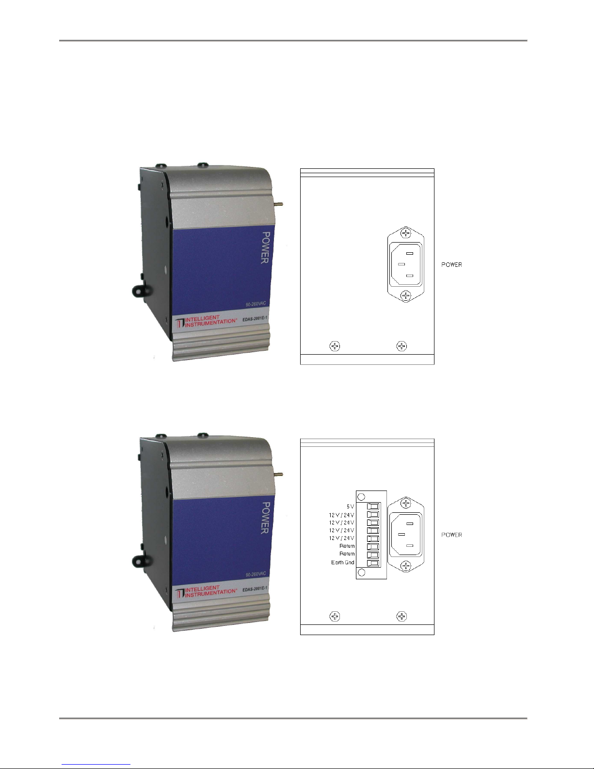
1.1.2 Power Supply
The EDAS-2001E power supply module provides power for the base unit and
attached modules. The EDAS-2001E can accept line voltages of 90 -260
VAC @ 50 -60 Hz.
FIGURE 1.4 EDAS-2001E-1 Power Supply Module
FIGURE 1.5 EDAS-2001E-2 and -3 Power Supply Module

Hardware and Installation 7
1.1.1.10 EDAS-2001E Power Supply Specifications
The EDAS-2001E supplies 5 VDC power to the CPU module which in turn
supplies power to the I/O modules. The -2 and -3 have quick a disconnect
connector that can be used to pull 5VDC and 12 VDC (-2) or 24 VDC (-3)
power from the supply to power other components in your system.
All specifications are typical at 25°C unless otherwise noted.
Parameter Condition Specification
Input Voltage 90 -260 VAC
Input Frequency 50 -60 Hz
Output Voltage
EDAS-2001E-15.0 V +/-5%
EDAS-2001E-25.0 V +/-5%
12.0 V +/-5%
EDAS-2001E-35.0 V +/-5%
24.0 V +/-5%
Output Current
EDAS-2001E-15 V 10.0 A max
EDAS-2001E-25 V
12 V 7.0 A max
2.5 A max
EDAS-2001E-35 V
24 V 7.0 A max
2.0 A max
Agency Approvals Tested to UL 60950
Dimensions inches
mm 4.55D x 5.9H x 3.35W
116D x 150H x 85W
Temperature Range Operating 0-60 °C
TABLE 1.2 EDAS-2001E Power Supply Specifications
1.1.1.11 Power Connector
The EDAS-2001E has a standard IEC power connector. Due to the wide range
of power sources and distance from the EDAS system a power cord is not
included with this module.

Hardware and Installation 8
1.1.3 Digital I/O Module
The EDAS-2002M Digital I/O Module has 8 digital inputs and 4 digital
outputs. The digital inputs and outputs are designed for 24 VDC
operation. All of the digital inputs and outputs provide 500 V channel
to channel isolation with one return per channel. LEDs provide visual
feedback on the channels’ current states. The digital inputs can be
individually configured for normal (high/low), counter or latched
operation. The digital outputs can individually configured for normal
(open/closed), pulsed, delayed and square wave output.

Hardware and Installation 9
FIGURE 1.6 EDAS-2002M Digital I/O module
1.1.1.12 Input Functions
The Digital I/O Module provides the following digital input functions.
The inputs can be configured on a channel by channel basis.
oNormal: Reads the current sates of the input (low/high).
oCounter: 24 bit up/down counter, 250 Hz maximum count rate.
oLatched: The input is latched on a low-to-high, high-to-low, or any
change of state.

Hardware and Installation 10
oHigh Speed Counter: Channel 0 only, 16-bit counter at 20 kHz maximum
count rate.
1.1.1.13 Output Functions
The Digital I/O Module provides the following digital output functions.
The outputs can be configured on a channel by channel basis.
oNormal: Set output to desired state (open/closed)
oPulsed: Set output active for a specified amount of time.
oDelayed: Set output active after the specified time delay.
oSquare wave: Generate a square wave with the specified period, 250 Hz
maximum.
1.1.1.14 EDAS-2002M Digital I/O Module Specifications
All specifications are typical at 25°C unless otherwise noted.
Parameter Condition Specification
Digital Input 8 inputs
Input Voltage Low 3.0 V max
Input Current Low Vin = 0.5 V > 500 nA
Input Voltage High 9 V min, 30 V max
Input Current High Vin = 24 V 5 mA max
Low Speed Counter Ch 0 through 7
Size 24 bit
Frequency 250 Hz max
High Speed Counter Channel 0 only
Size 16 bit
Frequency 20 kHz max
Digital Output FET output 4 Outputs
On resistance 0.03 Ω
On current 0.5 A max
On Voltage 0.8 V max
Off Voltage 27 V max
Isolation Inputs and Outputs
Channel -Channel 500 V max
Channel -Bus 1500 V max
Current Consumption 5 V 200 mA max
Dimensions inches
mm 4.55D x 5.9H x 1.74W
116D x 150H x 42W
Temperature Range Operating 0-60 °C

Hardware and Installation 11
TABLE 1.3 EDAS 2002M-1 Digital I/O Module Specifications

Hardware and Installation 12
1.1.4 Analog Input Module
The EDAS-2003M Analog Input Module can read voltage, current and
thermocouple inputs. Voltage, current or thermocouple readings can be
configured on a channel by channel basis, allowing one analog input
module to read a combination of voltage, current or thermocouple inputs.
FIGURE 1.7 EDAS-2003M Analog Input module

Hardware and Installation 13
The analog input stage consists of a 16 channel multiplexer (MUX),
followed by a programmable gain amplifier (PGA), feeding a 12-bit analog
to digital converter (ADC). The output of the ADC is isolated and
presented to the system bus. The MUX is capable of providing 16 single-
ended inputs, 8 differential inputs or a mixed combination to the PGA.
The PGA has gains of 1, 10 and 100. The ADC supports 0-10 V and ±10 V
ranges.
Current Readings: the module has 16 resistors (500 Ω) that may be
switched between the individual input channels and ground allowing the
unit to make current measurements in the range 0-20 mA.
Thermocouple readings: the module features a built-in Cold Junction
Compensator (CJC), which may be switched in to channel zero.
Additionally the module has 100 kΩ input bias return resistors that may
be switched in to provide an input bias current path for the PGA
1.1.1.15 Configuring Inputs
Each Analog Input channel can be configured for voltage input, current
input, or thermocouple input.
To configure a channel for voltage input:
1: Set the appropriate switches to disable current mode (SW2-1
through SW2-8 and SW3-1 through SW3-8). See the table below.
2: Set the appropriate switches to disable input ground return
resistor (SW1-1 through SW1-8).
3: The gain and range are set through software control.
To configure a channel for 0-20 mA current input:
1: Set the appropriate switches to enable current mode (SW2-1 through
SW2-8 and SW3-1 through SW3-8). See the table below. This
configuration requires the channel to be read as a single-ended
input.
2: Set the appropriate switches to disable ground return (SW1-1
through SW1-8).
3: In software set the PGA gain to 1 and the ADC Range to 0-10 V.
To configure an input for thermocouple input:
Note: Thermocouple can only be read on differential input channels 1
through 7. Channel 0 is used to read the CJC value.
1: Enable the differential ground return switches for the appropriate
channels (SW1-1 through SW1-8). See table below.

Hardware and Installation 14
2: Enable the CJC circuit (SW3-9). This will connect the CJC circuit
to channel 0 to be read as a single-ended analog input. If SW3-10
is turned on with SW3-9, the CJC may be read in differential mode.
Switch Number Switch ON Switch OFF
SW1-1GND return for differential Channel A0 No GND return
SW1-2GND return for differential Channel A1 No GND return
SW1-3GND return for differential Channel A2 No GND return
SW1-4GND return for differential Channel A3 No GND return
SW1-5GND return for differential Channel A4 No GND return
SW1-6GND return for differential Channel A5 No GND return
SW1-7GND return for differential Channel A6 No GND return
SW1-8GND return for differential Channel A7 No GND return
SW2-1Current mode enable Channel 8 Voltage mode enable Channel 8
SW2-2Current mode enable Channel 9 Voltage mode enable Channel 9
SW2-3Current mode enable Channel 10 Voltage mode enable Channel 10
SW2-4Current mode enable Channel 11 Voltage mode enable Channel 11
SW2-5Current mode enable Channel 12 Voltage mode enable Channel 12
SW2-6Current mode enable Channel 13 Voltage mode enable Channel 13
SW2-7Current mode enable Channel 14 Voltage mode enable Channel 14
SW2-8Current mode enable Channel 15 Voltage mode enable Channel 15
SW3-1* Current mode enable Channel 0 Voltage mode enable Channel 0
SW3-2Current mode enable Channel 1 Voltage mode enable Channel 1
SW3-3Current mode enable Channel 2 Voltage mode enable Channel 2
SW3-4Current mode enable Channel 3 Voltage mode enable Channel 3
SW3-5Current mode enable Channel 4 Voltage mode enable Channel 4
SW3-6Current mode enable Channel 5 Voltage mode enable Channel 5
SW3-7Current mode enable Channel 6 Voltage mode enable Channel 6
SW3-8Current mode enable Channel 7 Voltage mode enable Channel 7
SW3-9CJC enable CJC Disable
SW3-10 CJC differential mode CJC single-ended mode
* must be OFF when CJC circuit is enabled
Ground return resistors are 100 kΩ
TABLE 1.4 Current and Ground Return Resistor Switch Settings
1.1.1.16 Hardware / Software Pacing
The Analog Input Module has provisions for pacing (starting) conversions
by software or by one of two hardware start convert sources. These two
hardware sources are an internal 24-bit Rate Generator and a digital
input (EXT INT). The EXT INT input may also be used as a trigger signal
Table of contents
Popular Control System manuals by other brands


Helm
Helm PTM LOADGARD Series user manual

Audemo SYSTEMS
Audemo SYSTEMS PADES 2000 Series user manual

Gecko
Gecko in.xm2 Quick start card

Rinnai
Rinnai MANIFOLD ELECTRONIC CONTROL SYSTEM MSB-C1 installation instructions

DAHAO
DAHAO BECS-185 owner's manual

DELTA DORE
DELTA DORE TYPHONE 2 SV - GUIDE D Installation