airleben airLPT113 User manual

User manual
airLPT113
airLeakProofTester
www.airleben24.de
air
leben

2User manual |airLPT113
Version v1.0 |Status 24.11.2016
User manual
airLeakProofTester 113
Version 1.13 Status 05.2014
An airtightness test on ventilating and air-conditio-
ning systems is necessary to check that the required
airtightness class has been complied with and that
the ductwork is still therefore airtight. The require-
ments of ventilating and air-conditioning systems
are based on DIN EN 13779 “Ventilation of non-re-
sidential buildings – general principles and require-
ments of ventilating and air-conditioning systems.”
Leaking ventilation systems waste energy. Energy
savings can be made by making air lines more air-
tight. Furthermore, leaking systems can pose hygie-
ne risks. Insufficient quantities of air at the destina-
tion point caused by leakages can have an adverse
effect on ambient conditions.
The airLPT113 serves to determine the volume of
leaked air and the airtightness class attained ac-
cording to DIN EN 13779, or DIN EN 1507 and DIN EN
12237, especially in air conditioning systems. Becau-
se the airtightness class is determined automati-
cally, the device has a wide range of applications
ranging from the smallest systems (8 m² surface
area) up to large systems.
The airLPT113, which is fully equipped and supplied
in a robust aluminium case, has been specially de-
signed for use on construction sites. The device is
light and easy to carry as it weighs less than 12 kg.
The hoses and accessories are conveniently packa-
ged in a robust carrying bag.
The device is simple to operate thanks to its clear
and user-friendly menu navigation. It is suitable for
positive and negative pressure tests. All the connec-
tions, the display and the thermal printer are cle-
arly laid out on the top of the device. The air hose
connection for underpressure measurement is led
out from the side of the device.
The automatic measuring process according to DIN
EN 1507 and DIN EN 12237 takes 5 minutes. The air
duct system to be tested is sealed off airtight from
the rest of the system. Test pressure is applied,
which is automatically regulated and maintained at
a constant level (+/- 5 % according to the relevant
standard), and the air leakage rate is determined.
The measurement report is printed on an integra-
ted thermal printer or transmitted to a USB stick for
data transfer.
If you would like to find out more about the techni-
cal aspects of the airLPT113, please visit our website
www.airleben.de or call us on +49 (0) 3621 51445-0.

3User manual |airLPT113
Version v1.0 |Status 24.11.2016
Inhaltsverzeichnis
General information.....................................................4
Technical data ................................................................5
Equipment / scope of delivery................................5
Operating controls........................................................6
Start-up............................................................................. 7
Overpressure measurement ....................................9
Underpressure measurement...............................10
Main menu ......................................................................11
Test automatically.......................................................11
Contents of the log printout .................................16
Manual test mode .......................................................17
Leak detection mode ................................................18
Setup mode..................................................................20
Setting the watch .....................................................20
Input protocol head ...................................................21
Choose the language............................................... 23
Log printer .................................................................... 23
Maintenance interval ...............................................24
Warranty........................................................................24
Declaration of conformity ...................................... 25
Troubleshooting.......................................................... 26
Accessoires / wear parts.........................................27
Appendix ........................................................................28
Notes ...............................................................................30

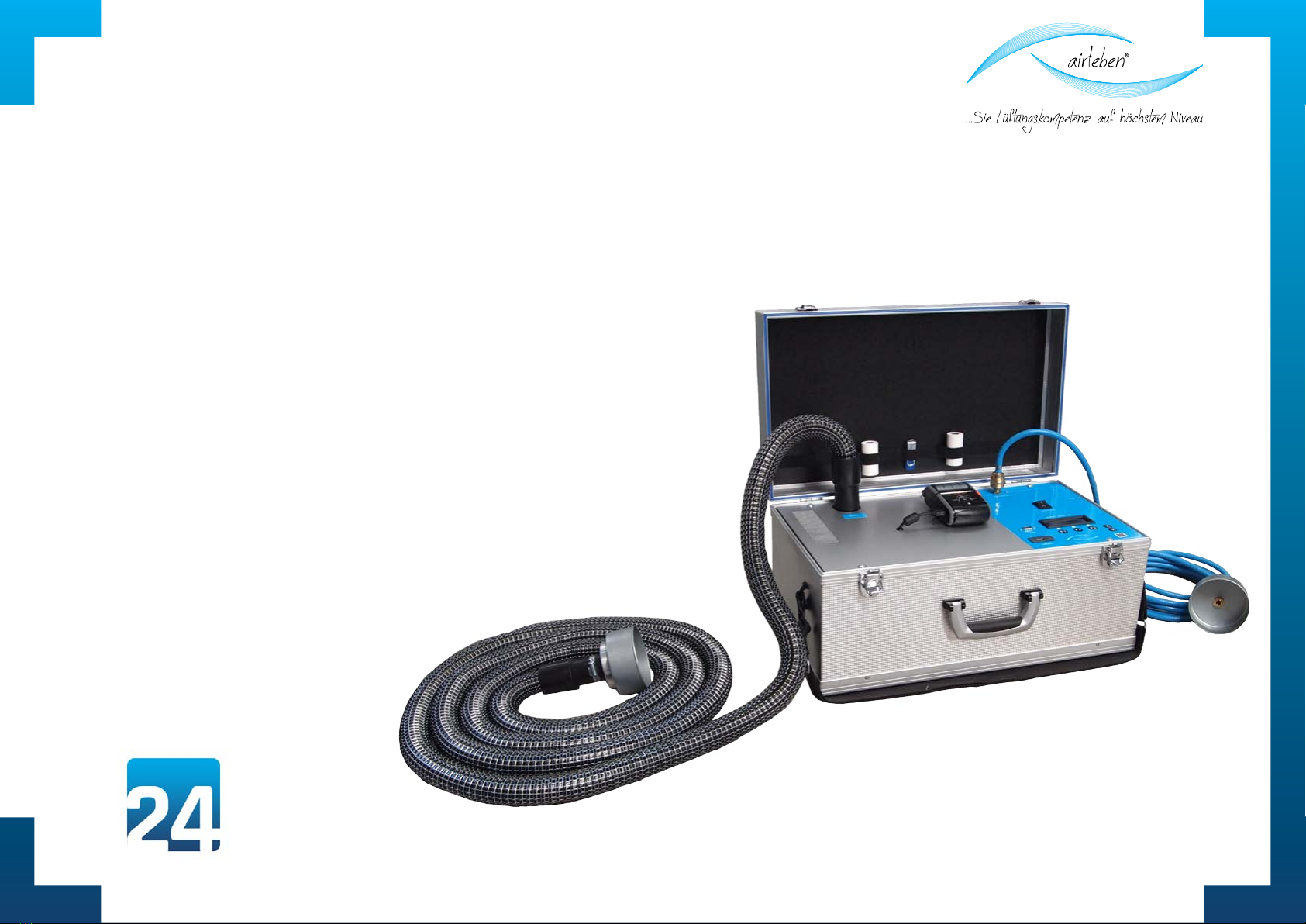
4User manual |airLPT113
Version v1.0 |Status 24.11.2016
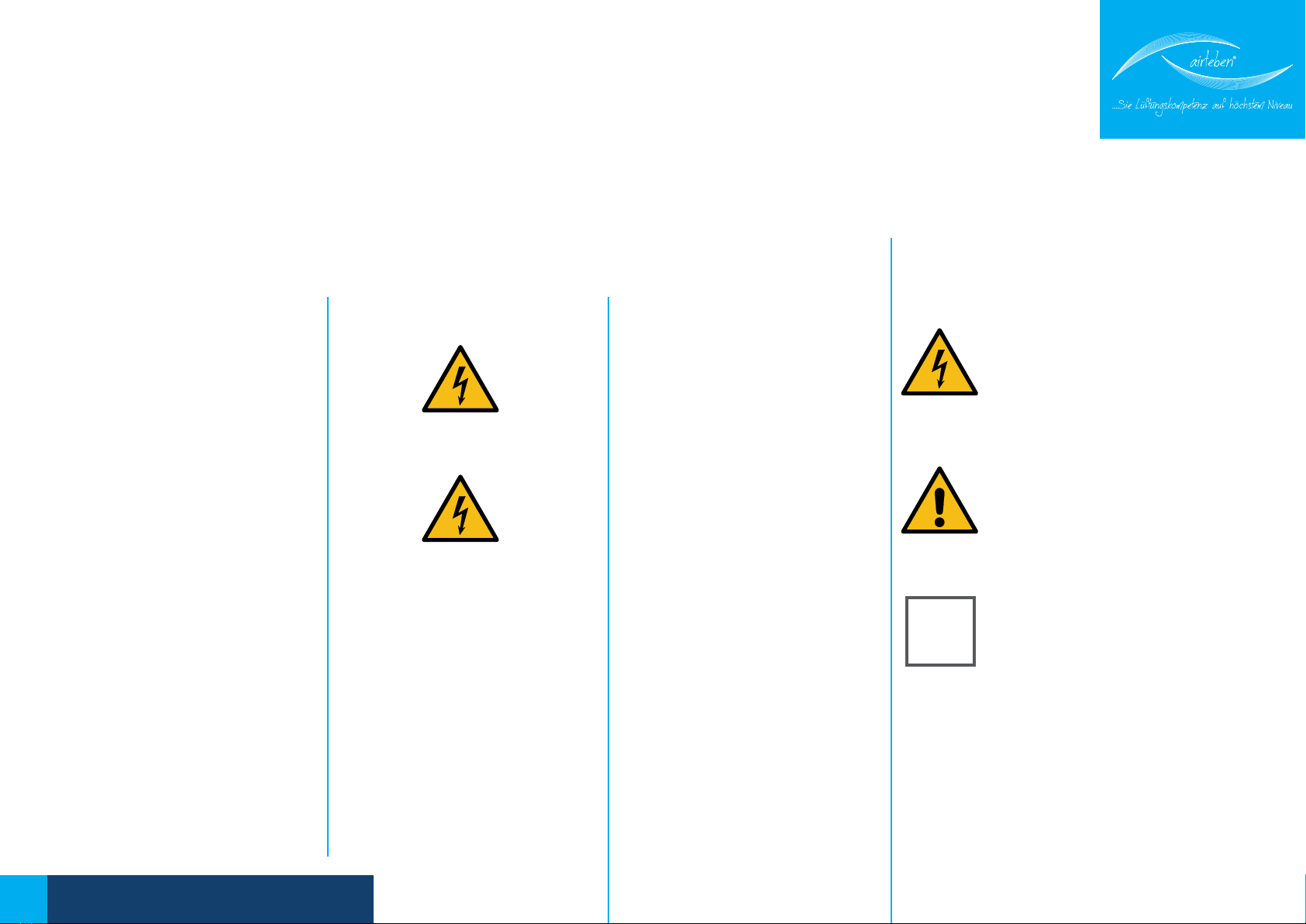
Explanation of the symbols
used
Danger from electricity. This sym-
bol warns of the dangers posed
by electric currents and dangerous
voltages.
Caution/important. This symbol
provides important information on
how to handle the equipment cor-
rectly.
Quick guide - a quick start guide to
using the airtightness testing de-
vice.
GENERAL INFORMATION
General information
The information provided in this
operating manual will enable you
to operate the airLPT113 safely.
Read this operating manual care-
fully and retain it for further refe-
rence.
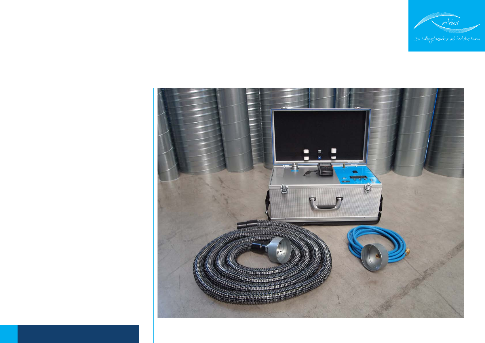
The airtightness testing device air-
LPT113 must be used solely by com-
petent personnel and used solely
for its intended purpose. The de-
vice was designed for testing the
airtightness of air duct systems,
especially in air conditioning sys-
tems and is intended to be used
as a measuring device. An exten-
ded search for leaks must be made
only in the leak search mode.
The device should be transpor-
ted, stored and used under dust-
free and dry conditions. Avoid the
connections for the air hose and
the pressure measuring hose beco-
ming contaminated (e.g. with dust
or moisture).
The device should never be opened
by the user.
Caution: Danger to life: 230 V, 50
Hz!
The device must be opened only
by a qualified and skilled person. If
the device fails to function, follow
the instructions in the section on
troubleshooting or contact the ma-
nufacturer.
Any modification to the original
condition of the device is not per-
mitted.
Sole responsibility rests with the
user and not the manufacturer for
any personal injury or material da-
mage caused by using the device
other than for its intended purpo-
se, or by a failure to follow the ins-
tructions in this operating manual.
Manufacturer
airleben GmbH
Goldbacher Straße 37
99867 Gotha
Tel.: 03621/51445-0
Fax: 03621/51445-219
www.airleben.de
Electronic devices must not be di-
sposed of with household waste.
They must be disposed of in ac-
cordance with the applicable en-
vironmental regulations. Defective
batteries are classed as hazardous
waste and must be disposed of at
the designated collection points.
K

5User manual |airLPT113
Version v1.0 |Status 24.11.2016
TECHNISCHE DATEN
Technical data
• 4 line illuminated display
• Voltage supply 230 V, 50 Hz
• Power input: max. 1500 W
• Weight: approx. 12 kg
• Dimensions (LWH):560 mm x 310 mm x 270 mm
• Operating range: +5 to +50°C
• Storage temperature: -20 to +50°C
• Operating capacity: 0.11 - 25 l/s; 0.40 - 90 m²/h
• Airtightness classes according to DIN EN 1507: LDK A / LDK B / LDK C / LDK D
• max. test pressure: +/- 2700 Pa
• Pressure measurement
• with piezo-resistive semiconductor sensor in the measuring range -3000
to +3000 Pa
• Resolution 2 Pa
• Combined error 1.8 % FS
• Flow rate measurement
• with hot film anemometer (standardised to 1013.25 hPa and 20°C)
• measuring range 0.11 to 36.5 l/s
• Resolution 0.01 l/s
• Combined error +/-5 % of MV
Equipment/scope of delivery
• 1 airLPT113 supplied in an aluminium case
• 1 carrying bag with carrying strap
• 1 power cable 230 V AC (length 2m)
• 1 air hose (length 5 m) with couplings for connection to the basic device
and the air duct system to be tested
• 1 air hose (length 5 m) for pressure measurement with couplings for
connection to the basic device and the air duct system to be tested
• 1 portable log printer with an integrated Li-ion battery, band size 57 mm
• 1 charger for the log printer
• 1 spare paper roll for log printer
• 1 copy of the operating manual/calibration protocol
• 2 keys for the aluminium case
• USB flash drive

6User manual |airLPT113
Version v1.0 |Status 24.11.2016
Operating controls
1. Slide flap
2. Power supply (power socket)
3. Fuse
4. Power switch
5. Display
6. USB flash drive
7. Air hose
8. Overpressure air connection
9. Underpressure air connection
10. Pressure measuring hose with detachable
adapter
11. Pressure measuring connection
12. Log printer
13. Serial interface (hardware preparation for
2nd expansion stage. No function has yet
been assigned to this interface).
1
9
2
3
5
6 101312
8
7
114
OPERATING CONTROLS

7User manual |airLPT113
Version v1.0 |Status 24.11.2016
Start-up
The airLPT113 is connected by the associated power lead
(power cable) to the electric supply network (230 V, 50 Hz)
and is switched on at the power switch (4).
Open the side flap (1) on the right hand side of the de-
vice.
After the device has been switched on, the display (5)
shows the firm, name of the device, the hard and soft-
ware version and the number of tests carried out since
the last inspection.
After the device has been switched on, the display
(5) shows the firm, name of the device, the hard and
software version and the number of tests carried
out since the last inspection.
After three seconds the device indicates on the
display (5) that internal tests (device self test) are
being carried out.
These tests comprise:
1. Display test (visual only)
2. Test of the back-up battery for the real-time
clock with warning if battery needs changing
3. Programme memory test
4. Parameter memory test
5. Keyboard test (to check if the keys are sticking)
6. USB flash drive test
7. Test to check the flow sensor is adhering to the
limit values of the signals.
8. Test to check the differential pressure sensor is
adhering to the limit values of the signals.
9. Starting up the fan for a short period
2
3
START-UP
Power
connection
Fuse
Arrow keys
and
K

8User manual |airLPT113
Version v1.0 |Status 24.11.2016
The display (5) then provides information on whether all the internal tests have
been passed or it displays an appropriate error message. If serious errors have
occurred (errors 3, 4, 5, 7, 8, 9), the device cannot be used or can be used only
to a limited extent. It must be repaired or sent in to the manufacturer for repair
(see also the section of troubleshooting on page 26).
A test of the USB drive (6) is also carried out (after the keyboard test), irrespec-
tive of whether a USB stick has been inserted.
If an error occurs in this test, a warning is displayed for 3 seconds on the dis-
play (5). This error is NOT a serious error. You can continue to use the device
although you will not be able to read and save data on the USB stick.
The storage capacity of the USB stick must not exceed 4 GB to prevent com-
plications arising with the software. We recommend you use the USB stick
supplied with the device.
START-UP

9User manual |airLPT113
Version v1.0 |Status 24.11.2016
OVERPRESSURE MEASUREMENT
Overpressure measurement
To carry out an overpressure measurement connect the air hose (7) to the over-
pressure air connection on the top side of the device (8).
Connect the pressure measuring hose (10) to the pressure measuring connec-
tion (11) which is also on the top side of the device. Connect both hoses to the
air duct system to be tested.
The air duct system to be tested must be sealed airtight from the rest of the
system. The use of foil and adhesive tape to seal the openings should be avoi-
ded as these usually lead to major measuring errors. The openings should be
sealed in a technically correct manner, e.g. by end caps. The airLPT113 is connec-
ted via prepared measuring openings. These can be, for example, flanged col-
lars or inspection openings with suitable adapters. According to DIN EN 12599
the test pressure as overpressure for supply air ducts or as underpressure for
air discharge ducts, should be 200 Pa, 400 Pa or 1000 Pa and should be at the
midpoint of the average operating pressure range.
10
7
K

10 User manual |airLPT113
Version v1.0 |Status 24.11.2016
UNDERPRESSURE MEASUREMENT
Underpressure measurement
To carry out an underpressure measurement connect the air hose (7) to the
underpressure air connection (9) on the right hand side of the device.
Connect the pressure measuring hose (10) to the pressure measuring connec-
tion (11) on the upper side of the device. Connect both hoses to the air duct
system to be tested.
The air duct system to be tested must be sealed airtight from the rest of the
system. The use of foil and adhesive tape to seal the openings should be avoi-
ded as these usually lead to major measuring errors. The openings should be
sealed in a technically correct manner, e.g. by end caps. The airLPT113 is connec-
ted via prepared measuring openings. These can be, for example, flanged col-
lars or inspection openings with suitable adapters. According to DIN EN 12599
the test pressure as overpressure for supply air ducts or as underpressure for
air discharge ducts, should be 200 Pa, 400 Pa or 1000 Pa and should be at the
midpoint of the average operating pressure range.
10
7
K

11 User manual |airLPT113
Version v1.0 |Status 24.11.2016
OPERATING
Main menu
NThe main menu is displayed after the device self tests have been passed. The
display shows the operating modes that can be selected:
• Test Automatically
• Test Manually
• Leak detection mode
• Set-up mode
The menu used when the device was last operated is indicated by an arrow.
To use this menu again, simply press the ENTER key. Otherwise you can select
another menu by using the arrow keys and
Test automatically
The saved input parameters of the previous test are shown on the display,
namely
• in line 1 - leakproof class A, B, C or D
• in line 2 - the test pressure, signed
• in line 3 - the air duct surface
K

12 User manual |airLPT113
Version v1.0 |Status 24.11.2016
OPERATING
In this menu the keys have the following labels and meaning.
F1 - MAIN Return to the main menu
F2 - CHANGE Jump to submenus to change the parameters “Tightness
class”, ”Test pressure” and “surface” An arrow in the respecti-
ve line shows which menu you have jumped to. The arrow can
be moved vertically by the arrow keys and
F3 - START Start the test
As the input parameters from the previous test have been saved, you can repe-
at a test simply by pressing the START key (F3).
In the Leakproof class submenu you can choose
between the airtightness classes A, B, C or D.
F2 – CHANGE Change the “leakproof class” parameter”
In the Test pressure submenu
you can set the test pressure between the limits – 3000 to +3000 Pa in 10 Pa
steps by using the arrow keys and If you hold down the arrow keys for
more than 1.5 seconds, the pressure value is changed quickly.
F2 – CHANGE Change the “test pressure” parameter

13 User manual |airLPT113
Version v1.0 |Status 24.11.2016
OPERATING
In the SURFACE submenu
you can set the surface between the limits of 3 to 300 m2in 0.1 m2steps by
using the arrow keys ²and ². If you hold down the arrow keys for more than 1.5
seconds, the surface value is changed quickly.
F2 – CHANGE Change the “surface” parameter
Testing starts after the START (F3) key has been pressed. The current pressure
in Pa and the flow rate in l/s (to two decimal places) are displayed constantly.
The automatic control system adjusts the pressure to the preset test pressure.
As soon as the pressure is accurate to within +/- 5%, the actual measuring
time of 5 min starts. A counter tells you how much measuring time is left. This
counter is stopped if the test pressure goes outside the abovenamed tolerance
zone once during the test.
You can terminate the automatic testing prematurely by pressing the STOP key
(F3). An evaluation is then made on the basis of the measuring time elapsed
up to this point. However, a statement is not made as to whether the test was
passed as the test was not carried out over a period of 5 min as required by
the standard (see EN 1507:2006 paragraph 5.22).

14 User manual |airLPT113
Version v1.0 |Status 24.11.2016
If the leak volume at the test pressure set exceeds 36.0 l/s, the measurement
is aborted with the following error message:
VOL. FLOW TOO BIG! PLEASE DECREASE VOLUME FLOW!
If the leak volume lies below the lower measurement limit of 0.11 l/s at the test
pressure set, the measurement is aborted with the following error message:
VOL. FLOW TOO SMALL! PLEASE INCREASE VOLUME FLOW!
After the expiry of the test period the display (5) shows the following data:
Test pressure [Pa]
Average flow rate, i.e. leak volume [l/s]
Maximum permitted flow rate (leak volume) according to class and surfa-
ce [l/s]
Test passed or test not passed
If the test was not passed, the entire line (“NOT passed”) flashes on and off, i.e.
the display changes periodically.
OPERATING

15 User manual |airLPT113
Version v1.0 |Status 24.11.2016
After the test has ended, the keys have the following function:
F1 - MAIN Return to the main menu
F2 - BACK Return to “automatic test mode” to repeat the test
F3 - PRINT Print-out by log printer (12)
The measured values and test result are printed when the key is pressed again.
You can print the log from this menu as many times as required. If the printer is
not switched on, the error message “Printer not ready. Please switch
it on” appears on the display (5) when the print function is started.
After the printer has been switched on, the “PRINT” (F3) key can be
pressed again.
If the USB stick supplied is in the associated drive (6) at the start of the printing
process, the log printout is written in parallel as a text file on the USB stick. The
file name comprises the letters LPT and the 5 digit test number, e.g.”LPT00123.
TXT”. The date and time the file was created are saved and can be seen when
the files are listed, e.g. in WINDOWS Explorer. This file will be written once only
on the USB stick, irrespective of how often the hard copy log is printed.
OPERATING
K

16 User manual |airLPT113
Version v1.0 |Status 24.11.2016
LOG PRINTOUT
PrintoutContents of the log printout
The log is printed in German or in English, according
to the language selected (the example shown here
is in English).
Log header
The log header contains seven lines which are freely
configurable by the user, each comprising 32 charac-
ters for setting out company data.
To configure these lines see the section on inputting
the log header.
AIR LEAK PROOF TEST
“airleben airLPT113” “HW-Version 1.0”; “SW-Version 1.0”
Consecutive test numbering since last inspection
Date
Time
“Airtightness test on air duct according to the
EN 12237, EN 1507 and EN 12599 standards”
“Data of text pieces”
• Mode of operation, manual or automatic
• Airtightness class selected, test pressure ap-
plied [Pa]
• Surface [m2] input
• Average pressure actually attained [Pa]
• Measuring time during which the test pressure
was in the tolerance window [sec]
• Average volume of leaked air [l/s]
• Maximum permitted volume of leaked air at the
specified test pressure and surface in class A, B,
C and D [l/s]
if measuring time >= 5 min:
”Test object ok or not ok“
this line is printed in twice the font size
if measuring time < 5min:
“Valuation not possible as test duration was less
than 5 min.”
The maximum volumes of leaked air for the four air-
tightness classes are displayed.
Signature of the inspector
Signature of the client

17 User manual |airLPT113
Version v1.0 |Status 24.11.2016
OPERATING
Manual test mode
This corresponds to the automatic test mode with the following exceptions:
1. The test pressure must be manually adjusted to the set point value that
has been input. This is done by changing the fan speed.
2. Measurements beyond the time limit of 5 min can also be made.
After the start key (F3) has been pressed, the fan does not start up automati-
cally but must be adjusted by the arrow keys and to a speed of rotation at
which the preset test pressure is maintained between the limits +/- 5%. If you
hold down the arrow keys for more than 1.5 seconds, the fan speed is changed
quickly.
The current pressure in Pa and the flow rate in l/s (to two decimal places) are
displayed constantly. In addition, a numerical value between 0 (speed of ro-
tation =0 and 2180 (maximum speed of rotation) appears in the display (5) to
indicate the speed of rotation of the fan. A countdown counter counts down
from 5 minutes to 0 whenever the test pressure is in the tolerance window.
Thereafter, however, you may continue the test for as long as required. To ter-
minate the measurement press the STOP (F3) key.
The average of the measured values from the entire measuring time is used
for assessment purposes. However, if the measuring time in which the test
pressure was in the tolerance band was under 5 min, no statement is made
as to whether the test was passed as this test was not carried out over a pe-
riod of 5 min as required by the standard. The same also applies to automatic
measurement.
The test can be logged in the same way in the manual test mode as in the
automatic mode (see also page 15).

18 User manual |airLPT113
Version v1.0 |Status 24.11.2016
LEAK DETECTION MODE
Leak detection mode
This mode serves to load the air duct system with a constant pressure over a
specific period of time in order to seek leaks in this period.
No volume flow measurement and display are carried out.
After this mode has been selected, the saved parameters from the previous
use of the leak search mode are displayed on the display, namely
in line 1 - the test pressure
in line 2 - the duration of the test
The keys have the following labels and meaning:
F1 - MAIN Return to the main menu
F2 - CHANGE Jump to the submenus to change the test pressure and
duration parameters. An arrow in the respective line shows
which menu you have jumped to. The arrow can be moved
vertically by the arrow keys and .
F3 - START Start the leak detection mode.

19 User manual |airLPT113
Version v1.0 |Status 24.11.2016
LEAK DETECTION MODE
In the TEST PRESSURE submenu
you can set the test pressure between the limits 10 to 500 Pa in 10 Pa steps by
using the arrow keys and (the pressure setting is 200 Pa when you call
up this mode for the first time). If you hold down the arrow keys for more than
1.5 seconds, the pressure value is changed quickly.
F2 – CHANGE Change the “pressure” parameter“
In the submenu DURATION you can set a test time
from between 1 to 30 min in 1 min steps by using the arrow keys and (the
time setting is 15 min when you call up this mode for the first time). If you hold
down the arrow keys for more than 1.5 seconds, the time value is changed
quickly.
F2 – CHANGE Change the “time” parameter
The Leak Search Mode Testing starts after the START key (F3) has been pres-
sed. The current pressure in Pa and the remaining time is displayed continuous-
ly. The device switches off the fan when the time has expired. You can also
terminate this mode prematurely by pressing the STOP key (F3).

20 User manual |airLPT113
Version v1.0 |Status 24.11.2016
SETUP-MODE
Setup-Mode
This menu contains the following submenus:
Setting the watch
Input Protocol Head
Choose the language
Selections are made as for the main menu by using the arrow keys.
Setting the watch
The integrated real-time clock can be set in this menu.
Day, month and year (two digit) as well as hour and minute (two digit) are each
set. The arrow keys and serve to increment and decrement the parame-
ters. By pressing the OK key the clock is started exact to the second for the
minute input and is returned to the main menu.
Date and time have the following format according to the language selected:
German: xx.xx.xxxx (day, month, year)
xx:xx (hours, minutes 24 hour display)
Englisch: xxx (day, month, year)
xx:xx (hours, minutes 12 hour display) with AM or PM indicator
This manual suits for next models
1
Table of contents
Other airleben Test Equipment manuals