airleben airLPT216 User manual

User manual
airLPT216
Air leakproof tester

34 Operating Instructions |airLPT216
Version 1.2 |Dated: 07.03.2017
Table of Contents
General notes ..............................................................36
Intended use................................................................36
Technical data .............................................................38
Equipment / scope of supply ...............................38
Controls..........................................................................39
Startup ..........................................................................40
Positive pressure measurement.........................42
Negative pressure measurement.......................43
Main menu ....................................................................44
Automatic test mode ......................................44
Contents of the record printout .........47
Manual test mode ............................................48
Leak detection mode.......................................49
Setup mode.........................................................50
Setting the clock (watch)......................50
Language selection .................................50
Entering the record header...................51
Class Z ........................................................... 52
Test duration .............................................. 52
Record printer.............................................................. 52
airLPT216 Android APP............................................. 53
Startup................................................................... 53
Main menu............................................................54
Automatic test mode ......................................54
Manual test mode ............................................ 56
Leak detection mode........................................57
Setup mode..........................................................57
Service interval ...........................................................58
Guarantee......................................................................58
Declaration of conformity ...................................... 59
Troubleshooting..........................................................60
Accessories / wearing parts ..................................61
Appendix ........................................................................ 62
Leakage values...........................................................63
Other languages/ Weitere Sprachen
Deutsch............................................................ 2
English ..............................................................33
Français............................................................65
Italiano ............................................................. 97
Svenska.......................................................... 129

35 Operating Instructions |airLPT216
Version 1.2 |Dated: 07.03.2017
Operating instructions
Air leakproof tester (airLeakProofTester 216)
airLPT216
Version 1.2 Dated 07 March 2017
An air leakage test on air conditioning systems is
necessary to check for compliance with the required
air tightness class and thus the airtightness of the
ductwork system. The relevant standard on which
ventilation and air conditioning systems are based
is EN 13779 “Ventilation for non-residential buildings
– Performance requirements for ventilation and
room-conditioning systems”.
Leaking ventilation systems consume unnecessary
energy. The more airtight the ducting the higher the
energy savings. Furthermore, leaking systems can
have negative effects on hygiene. Lack of air flow
rate in the destination due to leakages can have ne-
gative effects on the room conditions.
The airLPT216 air leakproof tester is used to deter-
mine the quantity of air leaked and the air tightness
class achieved according to EN 13779, or EN 1507 and
EN 12237, especially in HVAC systems. Due to the au-
tomatic determination of the air tightness class there
are a wide range of applications from very small sys-
tems (7 m2surface area) through to large systems.
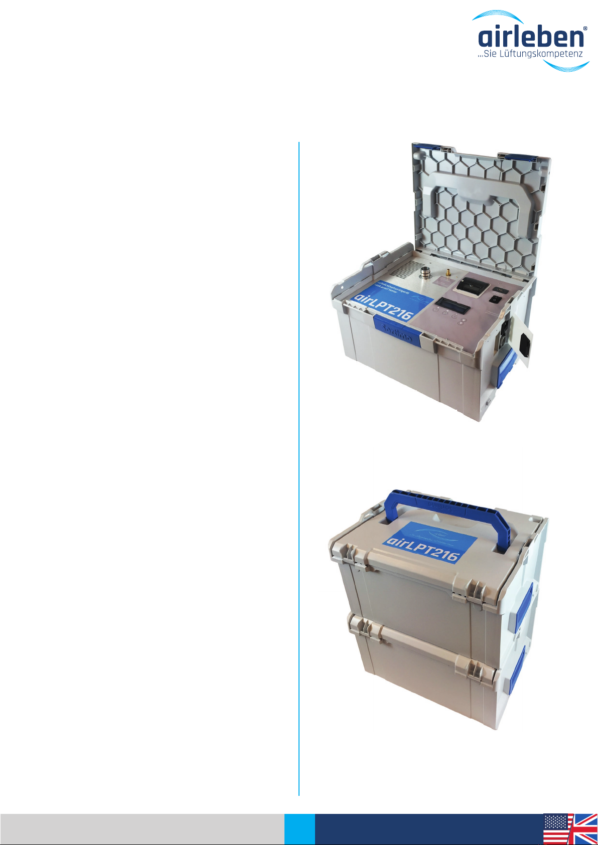
The airLPT216 air leak proof tester, with its complete
equipment and integration in a stable plastic case,
has been especially designed for use on construction
sites. It weighs less than 9.5 kg and is therefore light
and easy to transport. The hoses and accessories are
handily packed in a stable plastic case.
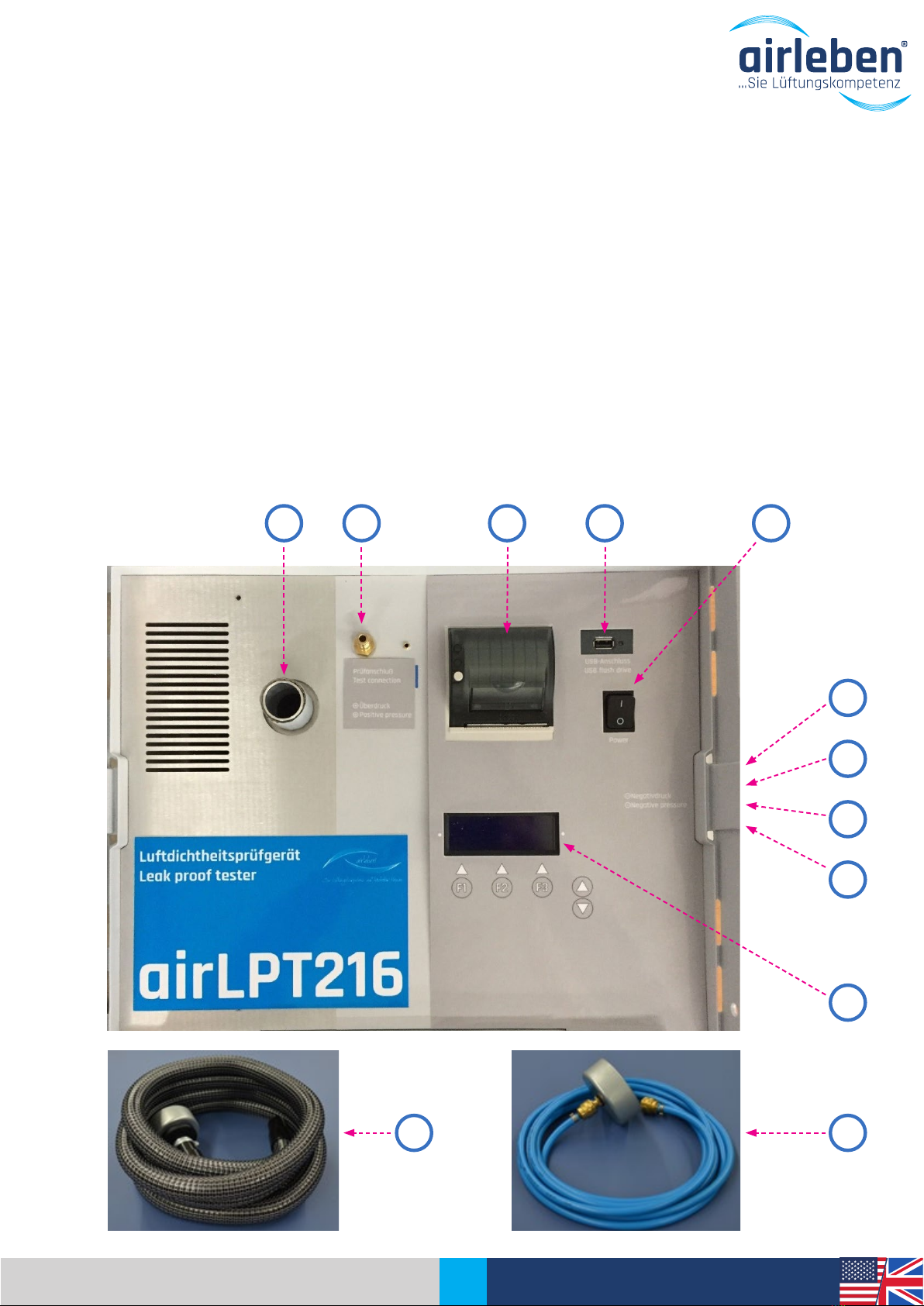
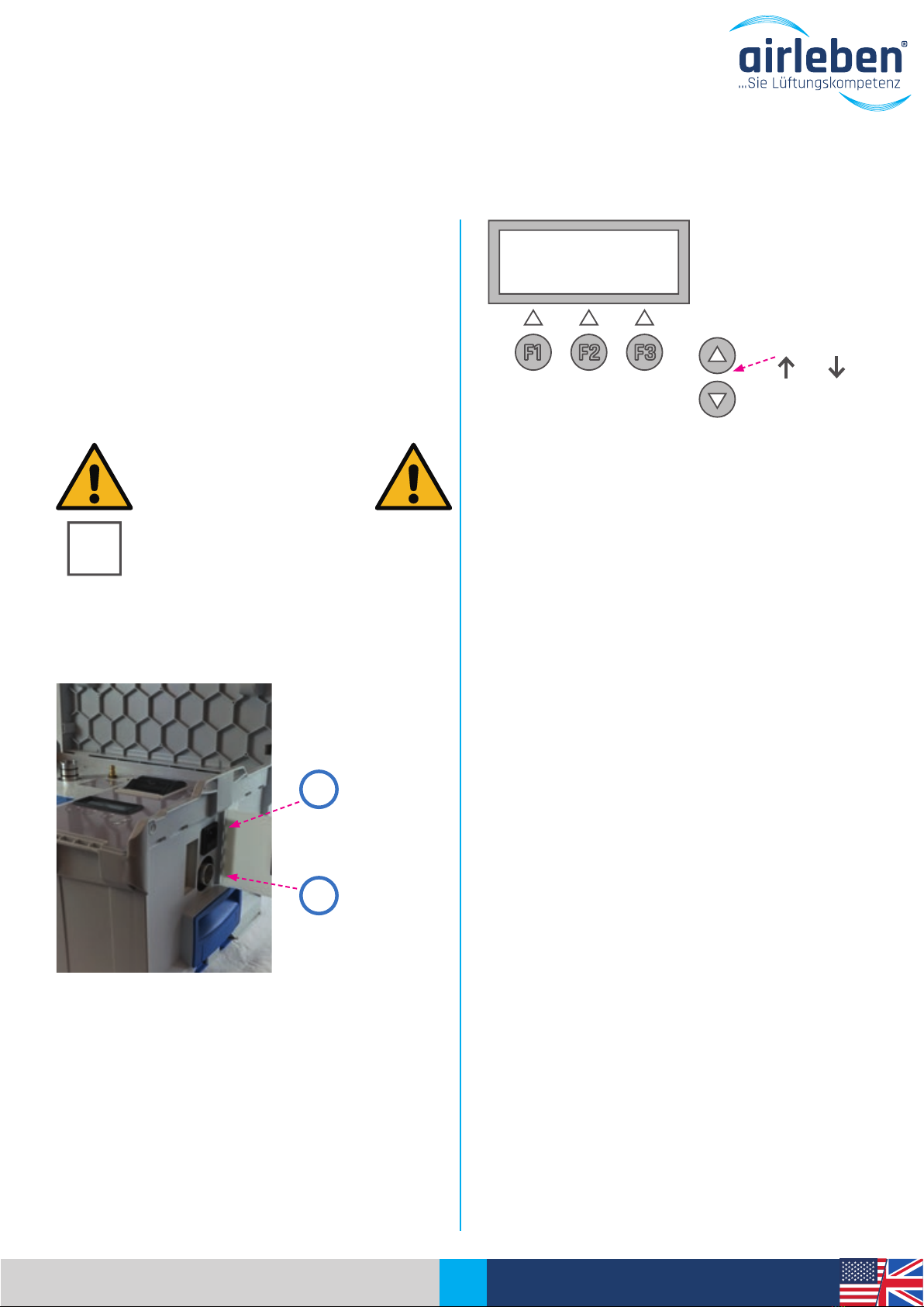
Clear and user-friendly menu navigation makes the
device easy to operate. It is suitable for positive and
negative pressure tests. All connections, the display
and the thermal printer are clearly arranged on the
top. The air hose connection for the negative pressu-
re measurement is at the side.
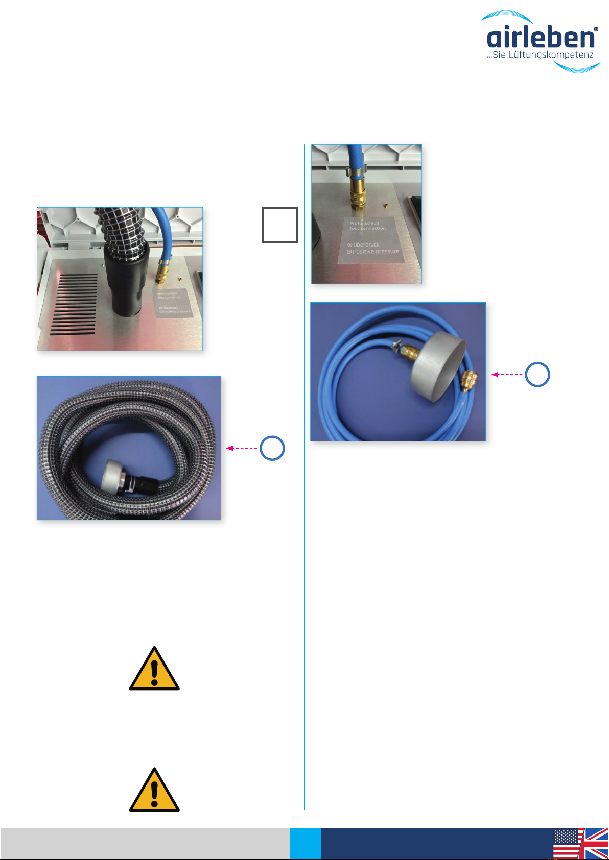
The automatic measurement sequence to EN 1507
and EN 12237 lasts 5 min. The air duct system to be
tested is sealed off airtight from the rest of the sys-
tem. It is pressurised, the test pressure is controlled
automatically and is kept constant (as defined by the
standard +/- 5 %) and the leakage air rate is deter-
mined. The measurement record is printed out using
an integrated thermal printer or the data is transfer-
red to a USB stick.
You are interested in further technical data and de-
tails of the airLPT216 air leak proof tester?
Then visit our website www.airleben.de or call us on
+49 3621 51445-0, we will be happy to advise you.

36 Operating Instructions |airLPT216
Version 1.2 |Dated: 07.03.2017
GENERAL INFORMATION
General notes
These operating instructions enable you to use the
airLPT216 air leak proof tester safely and reliably.
Read through these operating instructions and keep
them in a safe place.
Intended use
The airLPT216 air leak proof tester may only be used
by competent personnel and only for its intended
use. It has been design for air leakage testing of air
duct systems, especially in HVAC systems, and its in-
tended use is as a measuring device.
It is used to determine the quantity of air leaked and
the air tightness class achieved in HVAC systems ac-
cording to EN 13779, or EN 1507 and EN 12237. Due
to the automatic determination of the air tightness
class there are a wide range of applications from very
small systems (7 m2surface area) through to large
systems.
In addition to the measuring function, the measuring
device can also pressurise the connected system to
test pressure (positive pressure) for a defined time.
This function is intended for leakage detection. Con-
tinuous leakage detection may only be carried out in
Leak Detection mode.
The airLPT216 air leak proof tester may only be used
for the applications described above.
The user must prevent any use that is not intended
use. The test lines may only be pressurised with the
maximum positive or negative pressure for which
they have been designed. The airLPT216 air leak proof
tester is explicitly not intended for performing test
tasks in which the connected test object is expected
to be destroyed due to positive or negative pressu-
res.
Before performing the test, the mechanical strength
of the system to be tested must be checked. In par-
ticular, system parts that are not fixed or are partly
fixed, e.g. an unriveted end cover, can come off sud-
denly during the test sequence and can cause seri-
ous injuries, consequential damage and damage to
the airLPT216 air leak proof tester.
The device should be transported, stored and used in
a dust-free and dry environment. Avoid getting dirt
(e.g. dust, moisture) on the connections for the air
and pressure measuring hose.
In case of positive pressures higher than 2,000 Pa,
the two measurement connections - air connection,
pressure measurement connection - must be addi-
tionally secured against coming off suddenly at the
measurement openings.

37 Operating Instructions |airLPT216
Version 1.2 |Dated: 07.03.2017
Explanation of the symbols used
Electrical hazard - This symbol warns of
the hazards of electricity and dangerous
voltage.
Attention / Important - This symbol indi-
cates important notes on proper hand-
ling of the technology.
Quick start guide – The fast route to use
of the air leak proof tester.
K
The device should never be opened by the user.
Caution! Risk of fatal electric shocks at 230 V, 50
Hz!
The device may only be opened by a competent per-
son. If the device does not work, follow the instruc-
tions in the “Troubleshooting” section or contact the
manufacturer.
Changes to the original condition of the device are
not permitted.
All personal injuries and material damage caused by
any use that is not intended use or due to disregard
of these operating instructions are the sole respon-
sibility of the user of the device and not the manu-
facturer.
Manufacturer
airleben GmbH
Goldbacher Straße 37
99867 Gotha, Germany
Tel.: +49 3621 51445-0
Fax: +49 3621 51445-219
www.airleben.de
Important note on disposal
Electronic devices must not be disposed of in house-
hold waste, but in accordance with the relevant en-
vironmental regulations. Damaged rechargeable bat-
teries are hazardous waste and must be handed in to
the collection points provided for disposal.
GENERAL INFORMATION

38 Operating Instructions |airLPT216
Version 1.2 |Dated: 07.03.2017
TECHNICAL DATA
Technical data
• 4-line illuminated display
• Power supply: 230 V / 50 Hz
• Power consumption: max. 1,900 W
• Weight: approx. 9.5 kg
• Dimensions (L/W/H): 440 mm x 370 mm x 253 mm
• Working range: +5 to +50 °C
• Storage temperature: -20 to +50 °C
• Working range: 0.08 - 36 l/s; 0.29 - 130 m3/h
• Air tightness classes to EN 1507: Class A / Class B /
Class C / Class D
• Air tightness Class Z
• max. test pressure: -3,500 Pa / + 6,500 Pa
• Pressure measurement
• Ceramic measuring cell for differential pressure
measurements for -3,500 to +6,500 Pa
• Resolution 1 Pa
• Max. total error 1.5 % of the FS
• Volume flow measurement
• Mass flow rate measurement according to the calo-
rimetric measuring principle
• within the measurement range 0.08 to 36 l/s
• Resolution 0.01 l/s
Equipment / scope of supply
• 1 airLPT216 air leak proof tester integrated in the pla-
stic case
• 1 plastic transport case for accessories
• 1 mains cable 230 V AC (3 m long)
• 1 air hose (5 m long) with couplings for connecti-
on to the tester and to the air duct system to be
tested
• 1 hose (10 m long) for pressure measurement, with
couplings for connection to tester and to the air
duct system to be tested
• 2 spare paper rolls for record printer
• 1 operating instructions/calibration record
• USB stick
Note:
Changes to the technical data and available accessories for the product can occur at any time as part
of further technical development.

39 Operating Instructions |airLPT216
Version 1.2 |Dated: 07.03.2017
Controls
1. Side flap
2. Mains connection (power connection)
3. Device fuse
4. Mains switch
5. Display
6. USB port (max 4 GB)
7. Air hose
8. Positive pressure air connection
9. Negative pressure air connection
10. Pressure measuring hose with removable adapter
11. Pressure measurement
connection
12. Record printer
1
9
2
3
5
10
128
7
11 4
CONTROLS
6

40 Operating Instructions |airLPT216
Version 1.2 |Dated: 07.03.2017
STARTUP
Arrow buttons
and
K
airleben
airLPT 216
HWV 1.0 SWV 1.3
Tests: 487
F1 F2 F3
Startup
The corresponding mains connection cable (power cable) is
used to connect the airLPT216 air leak proof tester to the
electrical system (230 V, 50 Hz) and the device is switched
on at the mains switch (4).
Open the side flap (1) on the
right-hand side of the device.
There you will find the mains connection for the power ca-
ble and the device fuse
After switching on, the display (5) shows the compa-
ny name, name of the device, hardware and software
version and the number of tests performed since the
last inspection.
After three seconds the device signals on the display
(5) that internal tests (device self-tests) are being
performed.
In detail, these are:
1. Display test (visual only)
2. Test of the backup battery of the realtime watch
(clock) with warning if a battery change is requi-
red
3. Program memory test
4. Parameter memory test
5. Button test (possibly jamming buttons)
6. USB port test
7. Flow sensor test for compliance with the signal
limits
8. Differential pressure sensor test for compliance
with the signal limits
9. Brief starting up of the compressor (fan)
2
3
Mains connection
Device fuse

41 Operating Instructions |airLPT216
Version 1.2 |Dated: 07.03.2017
STARTUP
The display (5) then shows information on whether
all internal tests have been passed, or shows a cor-
responding error message. In case of fatal errors (er-
rors 3, 4, 5, 7, 8, 9), the device cannot be used, or only
to a limited extent, and must be handed in to the
servicing or sent to the manufacturer’s factory for re-
pair. (See also “Troubleshooting” section on page 60)
A test is also performed on the USB drive (6), where-
by it does not matter whether a USB stick is plugged
in or not.
If an error occurs, a warning appears on the display
(5) for 3 s. This error is NOT a fatal error, so that the
device can continue to be operated; however, without
the option of reading data onto the USB stick and
saving it.
The USB stick must not have a storage volume grea-
ter than 4 GB, as otherwise complications can occur
with the software. We recommend that you use the
USB stick supplied by us with the device.
SERV.DATE 08.02.17
14:39:19 06.03.17
SELFTEST ...
F1 F2 F3

42 Operating Instructions |airLPT216
Version 1.2 |Dated: 07.03.2017
POSITIVE PRESSURE
MEASUREMENT
Connect the air hose (7) for a positive pressure mea-
surement to the positive pressure air connection (8)
on the top of the device. Turning the hose coupling
slightly makes it easier to push on.
Connect the pressure measurement hose (10) to the
top of the device, at the pressure measuring connec-
tion (11). Connect both hoses to the measurement
connections on the air duct system to be tested.
These should be approx. 1.5 – 2 m apart and not be
opposite each other.
In case of pressures higher than 2,000 Pa, the two
measuring connections (air connection, pressure
measuring connection) must be additionally secured
against coming off suddenly.
The hoses must not be kinked, crushed or twisted.
The ductwork surface to be tested should be at least
10 m2for testing in conformity with the standards and
must be determined to EN 14239. The air duct system
to be tested must be sealed off airtight from the re-
maining system. Ensure careful sealing. Avoid using
film and adhesive tapes to close off the openings, as
in most cases this results in too large measurement
errors. The openings must be closed off properly, e.g.
using end caps. The air leakproof tester is connected
via prepared measuring openings. These can be, e.g.
flanged spigots, or inspection openings with approp-
riate adapters. According to EN 12599, the test pres-
sure, as positive pressure for supply air ducts and
negative pressure for exhaust air ducts, should be
200 Pa, 400 Pa or 1,000 Pa and lie in the middle of the
average operating pressure.
K
7
10

43 Operating Instructions |airLPT216
Version 1.2 |Dated: 07.03.2017
NEGATIVE PRESSURE
MEASUREMENT
Connect the air hose (7) for a negative pressure mea-
surement to the negative pressure connection (9) on
the right-hand side of the device. Turning the hose
coupling slightly makes it easier to push on.
Connect the pressure measurement hose (10) to the
top of the device, at the pressure measuring connec-
tion (11). Connect both hoses to the measurement
connections on the air duct system to be tested.
These should be approx. 1.5 – 2 m apart and not be
opposite each other.
In case of pressures higher than 2,000 Pa, the two
measuring connections (air connection, pressure
measuring connection) must be additionally secured
against coming off suddenly.
The hoses must not be kinked, crushed or twisted.
The ductwork surface to be tested should be at least
10 m2for testing in conformity with the standards
and must be determined to EN 14239. The air duct
system to be tested must be sealed off airtight from
the remaining system. Avoid using film and adhesi-
ve tapes to close off the openings, as in most ca-
ses this results in too large measurement errors. The
openings must be closed off properly, e.g. using end
caps. The air leakproof tester is connected via prepa-
red measuring openings. These can be, e.g. flanged
spigots, or inspection openings with appropriate ad-
apters. According to EN 12599, the test pressure, as
positive pressure for supply air ducts and negative
pressure for exhaust air ducts, should be 200 Pa, 400
Pa or 1,000 Pa and lie in the middle of the average
operating pressure.
K
7
10

44 Operating Instructions |airLPT216
Version 1.2 |Dated: 07.03.2017
OPERATION
Main menu
After the device self-tests have been completed suc-
cessfully the Main menu is displayed. The following
possible modes appear on the display:
• Automatic test mode
• Manual test mode
• Leak detection mode
• Setup mode
The menu used for previous operation of the device
is indicated by an arrow. If it is to be used again, it is
sufficient to press the ENTER button. Otherwise use
the arrow buttons and to select another menu.
Automatic test mode (as per
EN 1507 and EN 12237)
The saved input parameters of the preceding test are
shown on the display as follows
• in line 1 the air leaktightness class A, B, C, D or Z
• in line 2 the test pressure, with “+” for positive
pressure and “-” for negative pressure
• in line 3 the air duct surface area
In this menu the buttons have the following labelling
and meaning:
F1 - MAIN Back to Main menu
F2 - CHANGE Switch to submenus to change
the “Class”, “Test pressure” and
“Surface area” parameters. An ar-
row in the respective line indicates
the menu to which the program
switches. The arrow can be moved
vertically using the arrow buttons
and .
F3 - START Start of the test
As the input parameters of the previous test are sa-
ved, it is sufficient to press the START button (F3), if
a test is to be repeated.
In the CLASS submenu
you can choose between the air tightness classes A,
B, C, D or Z.
F2 – CHANGE Change the “air tightness class”
K
Remark:
Air tightness class Z is an air tightness class that can be freely defined by the user. The corresponding
leakage factor is defined in the Setup menu.
→ AUTOMATIC TEST
MANUAL TEST
LEAK DETECTION MODE
[ENTER]
F1 F2 F3
→ CLASS B
TEST PRESS. 400 Pa
SURFACE 20.0 m2
[MAIN | CHANGE | START]
F1 F2 F3
→ CLASS B
TEST PRESS. 400 Pa
SURFACE 20.0 m2
[MAIN | CHANGE | START]
F1 F2 F3
CLASS B
[ENTER]
F1 F2 F3

45 Operating Instructions |airLPT216
Version 1.2 |Dated: 07.03.2017
OPERATION
In the TEST PRESS. submenu
the arrow buttons and can be used to set the
test pressure within the limits –3,500 to +6,500 Pa in
5 Pa increments. If the arrow buttons are pressed for
longer than 1.5 s, the pressure value changes quickly.
F2 – CHANGE Change the “Test pressure”
parameter
In the SURFACE submenu
the arrow buttons and can be used to set the
surface area between 0.1 and 2,000 m2in 0.1 m2
increments. If the arrow buttons are pressed for
longer than 1.5 s, the surface area value changes
quickly.
F2 – CHANGE Change the “Surface” parameter
Start the test by pressing the START button (F3). The
current pressure in Pa and the volumetric flow in l/s
(with two decimal places) are displayed continuously.
The automatic mode controls the pressure to the pre-
defined test pressure. As soon as it is within +/- 5%
accuracy, the actual test time of 5 minutes begins. A
counter indicates the remaining test duration. This
counter is stopped if the test pressure leaves the
above-named tolerance range during the test.
The automatic test can be ended prematurely by
pressing the STOP (F3) button. The measurement pe-
riod that has passed up to this time is then evalua-
ted. However, no statement is made as to whether
the test was passed or not, as it was not performed
in conformity with the duration of 5 minutes required
in the relevant standard (see EN 1507:2006 Clause
5.22).
If the leakage volume at the set test pressure is abo-
ve 36.0 l/s, the measurement is cancelled with the
following error message:
VOLUME FLOW TOO
LARGE! PLEASE REDUCE
TEST PRESSURE!
If the leakage volume at the set test pressure is be-
low the measurement limit of 0.08 l/s, the measure-
ment continues, but a specific measurement value
cannot be determined. As a result “Leakage volume <
0.08 l/s” is then output.
TEST PRESS. 155 Pa
VOL FLOW 0.28 l/s
TIME LEFT 5:00 min.
[STOP]
F1 F2 F3
VOL. FLOW TOO HIGH!
PLEASE DECREASE
PRESSURE
[MAIN | CHANGE]
F1 F2 F3
Remark:
The test period is preset to 5 min. (300 sec.). In the Setup menu the test period can be freely set bet-
ween 30 and 300 sec. in 10 sec. increments.
CLASS B
→ TEST PRESS. 400 Pa
SURFACE 20.0 m2
[MAIN | CHANGE | START]
F1 F2 F3
CLASS B
TEST PRESS. 400 Pa
→ SURFACE 20.0 m2
[MAIN | CHANGE | START]
F1 F2 F3
TEST PRESS. 200 Pa
[ENTER]
F1 F2 F3
SURFACE 20.0 m2
[ENTER]
F1 F2 F3
TEST PRESS. 190 Pa
VOL FLOW 6.25 l/s
TIME LEFT 0:16 min.
[STOP]
F1 F2 F3

46 Operating Instructions |airLPT216
Version 1.2 |Dated: 07.03.2017
After the test period has expired the display (5)
shows the following data:
• average test pressure [Pa]
• average volume flow, i.e. leakage rate [l/s]
• maximum permitted volume flow (leakage rate) as
per class and surface area [l/s]
• Test passed (ok) or failed (not ok)
After ending the test the buttons have the following
function:
F1 - MAIN Back to Main menu
F3 - PRINT Printout by means of record printer
(12).
If the button is pressed again the measured values
and the test result are printed out.
The record can be printed out from this
menu as often as required.
If the USB stick supplied is in the corresponding drive
(6), the record printout is saved on the USB stick as
a text file at the same time. The file name is made
up of the letters LPT and the 5-digit test number, e.g.
“LPT00123.TXT”. The date and time when the file was
created are saved and are visible, for example, if the
files are listed in WINDOWS Explorer. This file is only
written on the USB stick once, regardless of how of-
ten the paper copy of the record is printed.
OPERATION
TEST PRESS. 197 Pa
ACT 0.29 MAX 5.58
TEST PASSED!
[MAIN] [PRINT]
F1 F2 F3
TEST PRESS. 1000 Pa
ACT 0.53 MAX 0.80
TEST PASSED!
[MAIN | BACK | PRINT]
F1 F2 F3
TEST PRESS. 193 Pa
ACT 6.59 MAX 5.50
TEST FAILED!
[MAIN] [PRINT]
F1 F2 F3
K

47 Operating Instructions |airLPT216
Version 1.2 |Dated: 07.03.2017
RECORD
PrintoutContents of the record printout
The record is printed out in the set language (shown here in German).
See also language setting in Setup Mode, page 51.
Record header
It contains seven lines, each with 32 characters, which are freely configu-
rable by the user to display company details.
For details of configuration of these lines, see
“Entering the record header” section.
„LEAKAGE TEST”
“airleben airLPT216” ; “Serial number”; “HW version 1.00” ; “SW version 1.07”
• Consecutive test numbering since last inspection
• Date
• Time
“Air leakage test on air ducts in compliance with standards EN 12237, EN
1507 and EN 12599”
“Data of test objects”
• Manual or automatic mode
• Selected air tightness class,
• Entered surface area [m2]
• Target test pressure [Pa]
• Actually achieved average pressure [Pa]
• Measuring time [sec]
• Average leakage rate [l/s] and [m3/h]
• Maximum permitted leakage flow rate for the given test pressure and
the given surface area in Class A, B, C and D [l/s] and [m3/h]
If measuring time = 5 min:
“Test object OK” or “Test object NOT OK”
this line is printed in twice the text size.
If measuring time < 5 min:
“Evaluation not possible as test duration was less than 5 min!”
The maximum leakage volume for the four air tightness classes is displayed.
Signature of the tester
Signature of the client

48 Operating Instructions |airLPT216
Version 1.2 |Dated: 07.03.2017
OPERATION
Manual test mode
This corresponds to automatic test mode, with the
exception that the test pressure must be adjusted
manually by changing the fan speed to the entered
target value.
After pressing the Start button (F3), the compressor
(fan) does not start automatically, but must be ad-
justed using the arrow buttons and to a speed
at which the preset pressure is kept within the limits
+/- 5 %. If the arrow buttons are pressed for longer
than 1.5 s, the compressor (fan) speed changes quickly.
The current pressure in Pa and the volumetric flow
in l/s (with two decimal places) are displayed con-
tinuously. In addition, a numerical value between 0
(speed = 0) and 4095 (maximum speed) appears in
the display (5) for orientation purposes and indica-
tes the speed of the compressor (fan). Whenever
the test pressure is within the tolerance window, a
countdown counter counts down from 5 minutes to 0.
The measurement ends after the time has expired or
by pressing the STOP (F3) button.
The evaluation uses the average of the measured
values from the entire test duration. However, if the
test duration during which the test pressure was wi-
thin the tolerance range band is less than 5 min, as
with the automatic measurement, no statement is
made whether the test was passed or not, as it was
not performed in conformity with the standard for a
duration of 5 minutes.
The same options for recording the test exist for
manual test mode as for automatic mode. (See also
page 46)
AUTOMATIC TEST
→ MANUAL TEST
LEAK DETECTION MODE
[ENTER]
F1 F2 F3
TEST PRESS. 1503 Pa
VOL FLOW 13.77 l/s
TIME LEFT 5:00 min.
MOTOR 805 M [STOP]
F1 F2 F3

49 Operating Instructions |airLPT216
Version 1.2 |Dated: 07.03.2017
LEAK DETECTION MODE
Leak detection mode
This mode is used to apply a constant positive pres-
sure to the duct system for a specific period of time,
to search for possible leaks during this time.
The air hose must be connected to the positive pres-
sure connection.
No volumetric flow measurement
or display takes place.
After selecting this mode, the saved parameters from
the previous use of Leak Detection mode are shown
on the display, namely
• in line 1 the test pressure
• in line 2 the duration
The buttons have the following labelling and meaning:
F1 - MAIN Back to Main menu
F2 - CHANGE Switch to the submenus to change the
test time and duration parameters. An
arrow in the respective line indicates the
menu to which the program switches.
The arrow can be moved vertically using
the arrow buttons and .
F3 - START Start Leak Detection mode.
In the TEST PRESS. submenu
the arrow buttons and can be used to set the
test pressure within the limits 50 to 500 Pa in 5 Pa
increments (the default pressure the first time this
mode is called up is 250 Pa). If the arrow buttons
are pressed for longer than 1.5 s, the pressure value
changes quickly.
F2 – CHANGE Change the “Pressure” parameter
In the DURATION submenu
the arrow buttons and can be used to set a test
duration of 1 to 30 min in 10 sec. intervals (the default
time when this mode is first called up is 15 min). If the
arrow buttons are pressed for longer than 1.5 s, the
time value changes quickly.
F2 – CHANGE Change the “Time” parameter
Leak detection mode starts after the START button
(F3) is pressed. The current pressure in Pa and the
remaining time are displayed continuously. The de-
vice switches off the fan
(compressor) after the
time has expired. The
STOP (F3) button can
also be used to end this
mode beforehand.
AUTOMATIC TEST
MANUAL TEST
→ LEAK DETECTION MODE
[ENTER]
F1 F2 F3
→ TEST PRESS. 250 Pa
DURATION 15:00 min
[MAIN | CHANGE | START]
F1 F2 F3
TEST PRESS. 250 Pa
[ENTER]
F1 F2 F3
DURATION 15:00 min
[ENTER]
F1 F2 F3
TEST PRESS. 158 Pa
TIME LEFT 14:55 min
[STOP]
F1 F2 F3

50 Operating Instructions |airLPT216
Version 1.2 |Dated: 07.03.2017
SETUP MODE
Setup mode
This menu contains the following submenus:
• Setting the clock (watch)
• Enter record header
• Language selection
• Class Z
• Test duration
The selection is made using the arrow buttons, as in
the Main menu.
Setting the clock (watch)
The integrated realtime clock can be set here.
The day, month (two-digit) and year (four-digit) and the
hour and minutes (two-digit) are each edited. The arrow
buttons and are used to increase and decrease
the parameters. By pressing the ENTER button the clock
is started at the entered minute accurate to the nea-
rest second and the program branches back to the Main
menu.
Depending on the selected language, the date and time
have the following format:
Language selection
This menu is used to select the language on the dis-
play (5) and on the paper printout from the record
printer (12).
You can choose between
• German
• English
• French
• Italian
• Swedish
The date and time format also change automatically
with the selection of the language.
MANUAL TEST
LEAK DETECTION MODE
→ SETUP-MODE
[ENTER]
F1 F2 F3
→ SET THE CLOCK
LANGUAGE SELECTION
ENTER RECORD HEADER
[BACK] [ENTER]
F1 F2 F3
YYYY-MM-DD hh:mm
2017-03-06 15:16
[ZURÜCK] [ENTER]
F1 F2 F3
→ SET THE CLOCK
LANGUAGE SELECTION
ENTER RECORD HEADER
[BACK] [ENTER]
F1 F2 F3
SET THE CLOCK
→ LANGUAGE SELECTION
ENTER RECORD HEADER
[BACK] [ENTER]
F1 F2 F3
→ DEUTSCH
ENGLISH
FRANCAIS
[ENTER]
F1 F2 F3
FRANCAIS
ITALIANO
→ SVENSKA
[ENTER]
F1 F2 F3

51 Operating Instructions |airLPT216
Version 1.2 |Dated: 07.03.2017
SETUP MODE
Enter record header
The header of the printed record is made up of seven
lines, each with 32 characters and can be used to
show the company name and address. These lines
are still empty when the device is delivered to the
customer by the manufacturer.
The customer can configure the record header easily
as follows:
A text only file with the name “KOPF.TXT” (HEADER.
TXT) is created at the PC using the WINDOWS text
editor. It must be ensured that this file contains only
7 lines, each with 32 characters. Any additional cha-
racters and lines are ignored. This file is copied onto
a USB stick. The USB stick does not have to be empty,
i.e. it can contain other data. However, it must not
have a storage volume larger than 4 GB, to prevent
complications with the software. The “KOPF.TXT” file
should be in the root directory.
The “Enter Record Header” menu item is opened at
the airLPT216. The user is then prompted to plug the
USB stick into the USB port (6) at the top of the de-
vice.
The file is transferred and the record header is per-
manently saved in the device. If the process is com-
pleted successfully, which only takes a few seconds,
the user is informed.
Otherwise an error message appears (e.g. if the KOPF.
TXT files was not found on the USB stick).
RECORD HEADER RECEIVED
WITHOUT ERRORS
F1 F2 F3
FILE NOT FOUND
F1 F2 F3
PLEASE PLUG IN USB
STICK WITH „KOPF.TXT“
[BACK] [ENTER]
F1 F2 F3
SET THE CLOCK
LANGUAGE SELECTION
→ ENTER RECORD HEADER
[BACK] [ENTER]
F1 F2 F3
K

52 Operating Instructions |airLPT216
Version 1.2 |Dated: 07.03.2017
SETUP-MODE
Class Z
Special test requirements require a leakage factor
that differs from the standardised air tightness clas-
ses. Use the arrow buttons and to set a value
between 0.0001 and 0.035 l/s. If the arrow buttons
are pressed for longer than 1.5 s, the value changes
quickly.
Stored leakage factors to EN 1507 and EN 12237:
• Class A – 0.027 l/s
• Class B – 0.009 l/s
• Class C – 0.003 l/s
• Class D – 0.001 l/s
Class Z – variable between 0.0001 and 0.035 l/s
(see also Appendix, page 62)
Test duration
For some test requirements it is also necessary to
use a different test duration. The arrow buttons
and can be used to set the test duration bet-
ween 30 and 300 s. If the arrow buttons are pressed
for longer than 1.5 s, the value changes quickly. The
test period is preset to 5 min (300 sec.) in the as-de-
livered test device.
Record printer
A record printer (12) is permanently installed on the air-
LPT216.
To change the paper roll, open it by carefully pulling the
roll cover (13) on the top of the printer.
The button (14) on the left-hand side of the printer
can be used to feed the paper manually.
K
12 13
14
ENTER RECORD HEADER
→ CLASS Z
TEST DURATION
[BACK] [ENTER]
F1 F2 F3
ENTER RECORD HEADER
CLASS Z
→ TEST DURATION
[ZURÜCK] [ENTER]
F1 F2 F3
TEST DURATION 5:00 min
[ENTER]
F1 F2 F3
CLASS Z 0.0010
[ENTER]
F1 F2 F3
Table of contents
Other airleben Test Equipment manuals
Popular Test Equipment manuals by other brands

YOKOGAWA
YOKOGAWA DL1640 user manual

Tektronix
Tektronix TDSDDM1 user manual

Multimetrix
Multimetrix VT 35 instruction manual

AlienTech
AlienTech KESSV2 Slave Instruction manual and users guide

Extech Instruments
Extech Instruments 380260-NIST user guide

Good Will Instrument
Good Will Instrument GSB-01 quick start guide