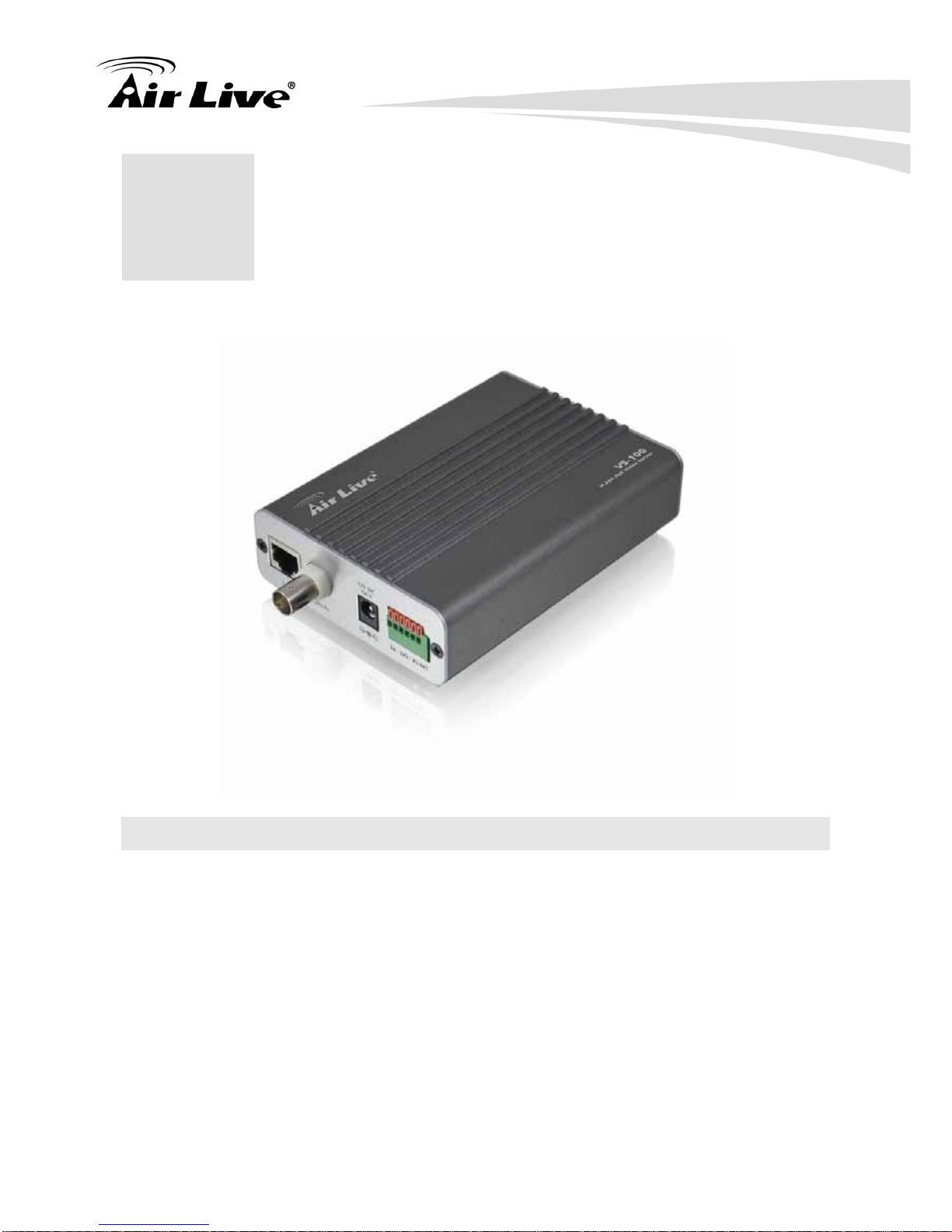
AirLive VS-100 User manual

VS-100
H.264 PoE Video Server
Use
r
’s Manual

Copyright and Disclaimer
Copyright & Disclaimer
No part of this publication may be reproduced in any form or by any means, whether
electronic, mechanical, photocopying, or recording without the written consent of OvisLink
Corp.
OvisLink Corp. has made the best effort to ensure the accuracy of the information in this
user’s guide. However, we are not liable for the inaccuracies or errors in this guide.
Please use with caution. All information is subject to change without notice
All Trademarks are properties of their respective holders.

Table of Contents
i AirLive VS-100 User’s Manual
Table of Contents
1. Overview...................................................................................................1
1.1 Introduction..............................................................................1
1.2 Product Features and Specification.........................................2
1.3 System Requirement...............................................................4
2. Package Contents and Installation ........................................................5
2.1 Package Contents...................................................................5
2.2 Hardware Overview.................................................................6
2.3 Hardware Installation...............................................................8
2.4 Search and Set up by IPWizard II .........................................11
2.5 Using UPnP of Windows® XP or Vista..................................16
3. Remote Access to VS-100.....................................................................17
3.1 Router....................................................................................17
3.2 Access the VS-100 via Internet Explorer...............................18
3.3 Logging in as an User............................................................19
3.4 Logging in as an Administrator..............................................19
4. Operating the Video Server...................................................................20
4.1 Live View ...............................................................................20
4.2 Administrating the Video Server............................................28
Appendix A: Alarm I/O Connector..............................................................73
A.1 Interfacing to the External I/O ...............................................73
A.2 Explanation of External I/O Circuit Diagram..........................74
Appendix B: FAQ .........................................................................................75
Appendix C: PING IP Address ....................................................................81
Appendix D: Bandwidth Estimation...........................................................82
Appendix E: Power Line Frequency...........................................................83
Appendix F: 3GPP........................................................................................85

1. Overview
1 AirLive VS-100 User’s Manual
1 1. Overview
1.1 Introduction
The VS-100 is an inexpensive fully scalable surveillance technology. Because the Video
Servers can be plugged into your existing local area network infrastructure, you will
potentially save thousands of dollars on unnecessary cabling.
The device is accessible via the LAN or Internet connection. Connect your Video Server
directly to a local area network or xDSL modem, and with Microsfto® Internet Explorer you
get instant, on demand video streams. Within minutes you can set up the device to capture
a video sequence to a PC. The live video can be uploaded to a website for the world to see.

1. Overview
AirLive VS-100 User’s Manual 2
1.2 Product Features and Specification
Feature Summery
zUpgrade your CCTV camera to network-enabled camera
zSupport up to D1 resolution
zMultiple H.264, Motion JPEG and MPEG-4 video streams
zSupport 802.3af Power over Ethernet function
zOne MicroSD slot for store video clips locally
zSupport RS-485, Digital Input and Digital Output for additional control
zUPnP and setup wizard for easy installation
zAddition 12V DC output for powering camera
z64 channel surveillance software
Specification
Model Name VS-100
Video Encoder H.264, MPEG4 and Motion JPEG simultaneously
(Tri-encoders)
Video Profile
9 profiles simultaneously
- H.264 4CIF / CIF / QCIF
- MPEG4 4CIF / CIF / QCIF
- M-JPEG 4CIF / CIF / QCIF
Frame Rate Up to 30fps for all profiles
Image Setting
De-interlace (4CIF resolution)
De-noise
Brightness, sharpness, contrast, color
Text, time and date overlay
Streaming Simultaneously multi-profile streaming
Streaming over UDP, TCP, or HTTP
Multicast streaming
M-JPEG streaming over HTTP
Supports 3GPP mobile surveillance
Controllable frame rate and bandwidth
Constant and variable bit rate (MPEG4 / H.264)

1. Overview
3 AirLive VS-100 User’s Manual
Audio
Audio Encoder RTSP: G.711 64kbps, G.726 32kbps
3GPP: AMR
Audio Streaming One-way or two-way
Audio Input Built-in or external microphone
Audio Output Line level out
Network
Supported Protocols TCP, UDP, HTTP, SMTP, FTP, NTP, DNS, DDNS, DHCP,
ARP, Bonjour, UPnP, RTSP, RTP, RTCP, PPPoE, 3GPP,
ICMP, IGMP, SAMBA
Security Password protection, IP address filtering, user access log
Users 20 simultaneous unicast users
Two-level user privilege
Ethernet 10/100M auto negotiation
System Integration
Alarm Triggers Intelligent video motion detection and external input
Motion Detection 10-zone video motion detection
Alarm Events
File upload via FTP or email
Notification via email, HTTP, and TCP
External output activation
Go to PTZ preset position
Audio alerting output
Video Buffer Pre- and post- alarm buffering
General
Power Supply 12V DC external power adapter
Power Consumption 4W
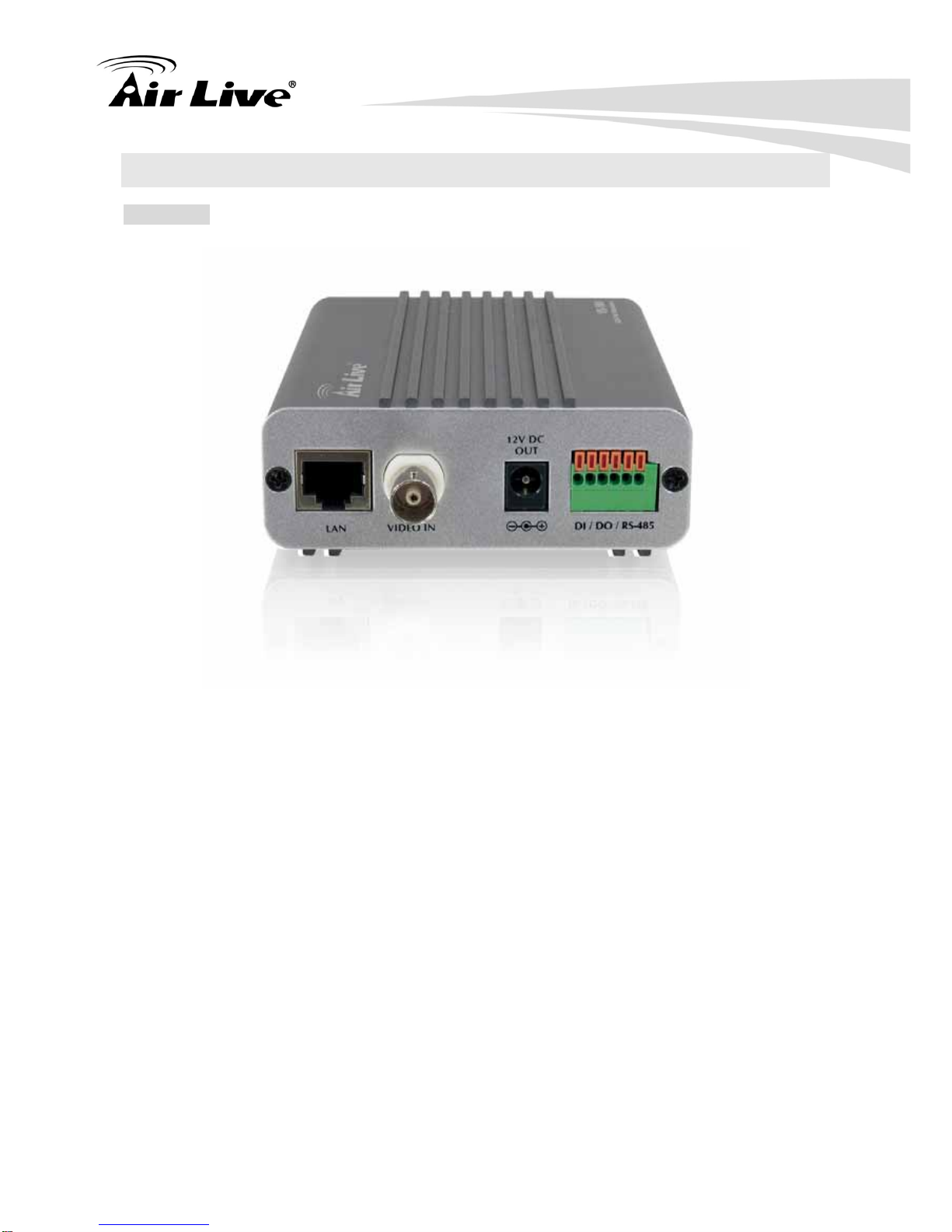
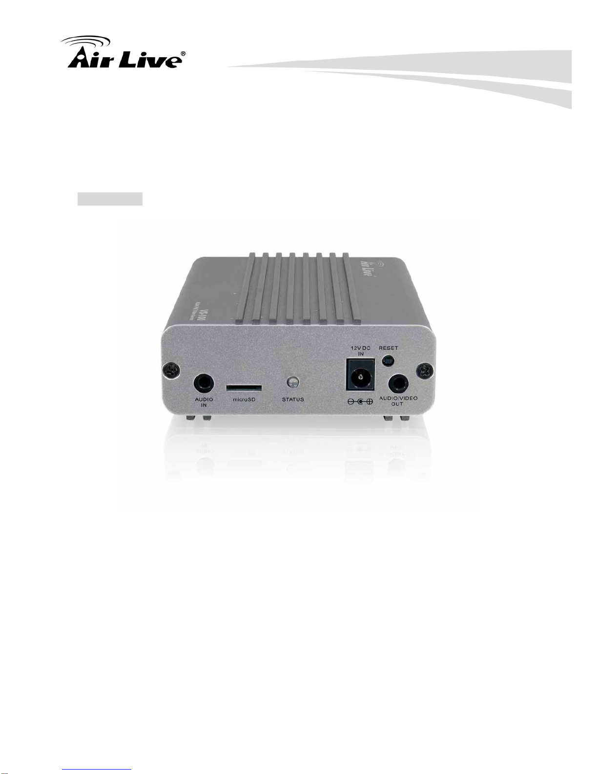
Connectors
RJ-45 10BaseT/100BaseTX , DC jack
1 alarm input and 1 output
RS485
External MIC in
Audio line out
Video out
Micro SD card
12V DC output (400mA max.)
Operating
Temperature 0°C ~ 40°C
Operating Humidity 20% ~ 80% (non-condensing)
Dimension 125X90X31mm (HXWXD)

1. Overview
AirLive VS-100 User’s Manual 4
Viewing System
OS Windows® XP, Vista
Browser IE 6.0 or latter, Firefox 2.0 or later, Safari
Cell Phone With 3GPP player
Video Player VLC, Quick Time, Real Player, Core Player
Software
Bundled NVR
Program CamPro Express 64, CamPro HD
1.3 System Requirement
zMicrosoft Internet Explorer 6.0 or later
zMicrosoft Media Player 11.0 or later (to playback recorded file)
zVGA Monitor resolution 1024 x 768 or higher
zPentium-4 2.0 GHz or higher
zMemory Size: 512MB or more
zWindows XP, Vista

2. Package Contents and Installation
5 AirLive VS-100 User’s Manual
2.1 Package Contents
User can find the following items in the package as below:
zVS-100 is the main element of the product.
zPower Adapter dedicates 12V DC electric power output to Video Server.
zPower cable for external camera to supply 12VDC power to external camera.
zA/V Cable is for audio line output (white cable) and video output (yellow cable).
zUser’s Manual CD provides important information and instructions for operating the
Video Server.
zQuick Start Guide provides important information and instructions for installing this
device.
Note: Using a power supply with a different voltage than the one included with the Network
Camera will cause damage and void the warranty for this product.
2 2. Package Contents
and Installation

2. Package Contents and Installation
AirLive VS-100 User’s Manual 6
2.2 Hardware Overview
Front Side
LAN Socket
The LAN socket is a RJ-45 connector for connections to 10Base-T Ethernet or 100Base-TX
Fast Ethernet cabling. This Ethernet port built N-Way protocol can detect or negotiate the
transmission speed of the network automatically. Please use Category 5 “straight through”
cable to connect the Video Server to a 100Mbps Fast Ethernet network switch or hub. Note
that, in case you need to connect the device to PC or notebook directly, you should use
“cross-over” cable instead.
Video-in Jack
You can Install 1 video camera and connect it to video-in jack.
12VDC-Out Jack
The output power is 12VDC. This is used to supply 12VDC power to one external camera.
The output power is 12VDC/400mA maximum.

2. Package Contents and Installation
7 AirLive VS-100 User’s Manual
DI/DO/RS485 and DI/DO Connector
The Video Server provides a terminal block with 6 pins of connectors for DIDO and RS485.
Please refer to the Appendix B in this manual for more information.
Bottom Side
Audio in Jack
Audio in (microphone) jack allows an external microphone attached to this device.
Micro SD Card Slot
User can insert a micro SD card into this slot for event recording.
Status LEDs
The Status LED will turn green while system is booting up successfully.
This LED is also used to indicate the status of Network connection. The LED will flash
green while some one accesses this Video Server.

2. Package Contents and Installation
AirLive VS-100 User’s Manual 8
12VDC-in Jack
The input power is 12VDC. Note that supply the power to the Video Server with standard
power adapter included in package. Otherwise, the improper power adapter may damage
the unit and result in danger.
Factory Default Reset
This button is hidden in the pinhole. This button is used to restore the all factory default
settings. Sometimes restarting the Video Server will make the system back to a normal
state. If the system still got problems after restart, user can restore the factory default
settings and install it again. To restore the device, please follow the steps below:
1. Insert the paper clip or other tool and press and hold the button down continuously.
2. Hold it at least 5 seconds and release the tool. Then the device has been restored to
default settings and reboot again.
Note: Restoring the factory default setting will lose the all previous settings included IP
address forever. User needs to run the IPWizard II program to search the device and
configure it to let the device work properly again.
Audio/Video Output Jack
Audio/Video-out Jack allows this device to output audio and video signal. Use the attached
A/V cable to connect A/V device where white cable is for audio and yellow cable is for
video.
2.3 Hardware Installation
1. Attach video source to Video Server
To use this device, user must supply video source to this device first. Typical, user may
utilize box camera, doom camera, bullet camera, P/T/Z camera, Speed doom camera, or
others as the video source. Connect the BNC terminal of camera to the device’s video input
and make sure to power on these cameras first. Otherwise, the operation may be incorrect.

2. Package Contents and Installation
9 AirLive VS-100 User’s Manual
2. Attach external microphone to Video Server (option)
If user needs not only video stream but also audio stream, then an external microphone
should be attached to Video Server. Connect an external microphone to the Video Server’s
audio input.

2. Package Contents and Installation
AirLive VS-100 User’s Manual 10
3. Plug an Ethernet cable into Video Server
Connect an Ethernet cable to the LAN socket located on the device’s panel and attach it to
the network.
4. Connect RS485 (option)
When users would like to apply a camera with P/T/Z function, they usually need to connect
their communication port (for camera control) through RS485. After RS-485 was correctly
connected to D+ and D-, the remote users could control the camera movement through
Internet.
5. Connect an external power supply to Video Server

2. Package Contents and Installation
11 AirLive VS-100 User’s Manual
Connect an external power supply to the 12VDC power in connector of the Video Server.
Note: Use the power adapter, 12VDC, included in the package and connect the other end to
wall outlet for AC power.
Once you have installed the Video Server well, the status LED will turn orange. It means the
system is booting up successfully. Furthermore, if you have a proper network connection,
and access to the Video Server, the LED will flash green
6. Connect the DC power to one external camera from Video Server (option)
The Video Server can provide 12VDC out to supply one external camera. Note that the
output current is 400mA maximum.
7. Done
2.4 Search and Set up by IPWizard II
When you installed the Camera on a LAN environment, you have two easy ways to search
your Cameras by IPWizard II or UPnP discovery. Here is the way to execute IPWizard II to
discover Camera’s IP address and set up related parameter in a Camera.

2. Package Contents and Installation
AirLive VS-100 User’s Manual 12
Search
When launch the IPWizard II, a searching window will pop up. IPWizard II is starting to
search Network Cameras on the LAN. The existed devices will be listed as below.

2. Package Contents and Installation
13 AirLive VS-100 User’s Manual
View
If IPWizard II finds network devices, View button will be available. Please select the device
you want to view and click the View button. Then you could see the video from camera
directly. Furthermore you could double click the left button of mouse to link to the network
device by browser.

2. Package Contents and Installation
AirLive VS-100 User’s Manual 14
LAN
In case you want to change the IP related parameters of wired interface, please select the
device you want to configure and click the LAN button. Relative settings will be carried out
as below.
You could modify the relative settings of the selected device. Click “<<” button will quit the
LAN setting procedure and click “>>” button will move to next page as below.

2. Package Contents and Installation
15 AirLive VS-100 User’s Manual
In case, you do not want to change username and/or password, then just click “Submit”
button to perform your setting accordingly. Click “<<” button will go back to previous page.
If you like to change username and/or password of the device, just click the check button.
Then, the related fields will show up as below.

2. Package Contents and Installation
AirLive VS-100 User’s Manual 16
After keying in new username and password, click “Submit” button to perform your setting
accordingly. Click “<<” button will go back to previous page.
Wireless
VS-100 does not support wireless function.
2.5 Using UPnP of Windows® XP or Vista
UPnP™ is short for Universal Plug and Play, which is a networking architecture that
provides compatibility among networking equipment, software, and peripherals. This device
is an UPnP enabled device. If the operating system, Windows XP or Vista, of your PC is
UPnP enabled, the Network Camera will be very easy to be found.
Please refer to Appendix J to enable UPnP settings only if your operating system of PC is
running Windows XP.
Note: Windows 2000 does not support UPnP feature.
To discover your device, go to your Desktop and click My Network Places.
Click the targeted Device. Then Internet Explorer will connect to this Network Camera
automatically.

3. Remote Access to VS-100
17 AirLive VS-100 User’s Manual
3.1 Router
Once installed, the device is accessible on your LAN. To access the device from the
Internet you must configure your broadband router to allow incoming data traffic to the
device. If the device is installed on the LAN with a router, then it may get a dynamic IP
address from the DHCP server. However, if the device wants to be accessed from the WAN,
its IP address needs to be setup as fixed IP, also the port forwarding or Virtual Server
function of router needs to be setup.
However, if your NAT router supports UPnP feature, it can be very easy to achieve NAT
traversal automatically. To do this, enable the NAT-traversal feature, which will attempt to
automatically configure the router to allow access to the camera.
Installing the device with an UPnP router on your network is an easy 3–step procedure:
1. Enable UPnP option of your NAT router
2. Enable UPnP NAT traversal option of the Network Camera (default)
3. Access your Network Camera by you public IP address
(1) Enable UPnP option of your NAT router
To use UPnP IGD function (NAT traversal), you need to make sure the UPnP function is
enabled in your router. Most new home routers should support this function. Some of
routers are default enable and others are not. Please check user’s manual of your NAT
router for detail.
(2) Enable UPnP NAT traversal option of the Network Camera
Refer to Setting ÎNetwork ÎUPnP page for detail NAT traversal setting. Note that this
option is default enabled.
(3) Access your Network Camera by DIPS
Refer to Setting ÎSystem ÎSystem page for detail DIPS information.
3 3. Remote Access to
VS-100
Table of contents
Other AirLive Server manuals
Popular Server manuals by other brands

Overland Storage
Overland Storage SnapServer XSD 40 Configuration guide

Alcatel-Lucent
Alcatel-Lucent 5070 SSG Specifications

Inspur
Inspur NF5266M5 installation guide

Lenovo
Lenovo ThinkServer RD120 Hardware installation guide

Lenovo
Lenovo ThinkServer RD120 Installationshandbuch

IBM
IBM 883725U Hardware announcement