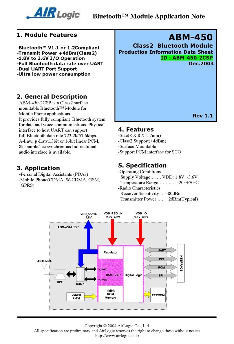
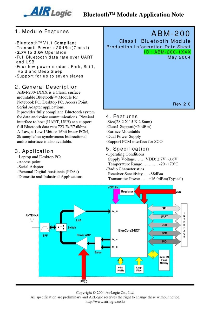
Airlogic ABM-600 Installation and operating instructions

Bluetooth®Module Application Note
Copyright ©2004AirLogic Co., Ltd.
All specification are preliminary and AirLogic reserves the right to change these without notice.
http://www.airlogic.co.kr
ABM-600
Class1Bluetooth Module
Production Information Data Sheet
ID : ABM-600-1XXXX
AUG.2004
Rev 1.0
1.
Module
Features
-Bluetooth®V1.2Compliant
-Transmit Power +20dBm(Class1)
-2.7V to 3.6V Operation
-Full Bluetooth data rate over UART
and USB
-Four low power modes : Park, Sniff,
Hold and Deep Sleep
-Support for up to seven slaves
-
Enhanced Data Rate(EDR) compliant
with V0.9 of specification for both
2Mbps and 3Mbps modulation
modes
2.
General Description
ABM-600-1xxxx is a Class1 surface
mountable Bluetooth®Module for
Notebook PC, Desktop PC, Access Point,
Serial Adapter applications.
It provides fully compliant Bluetooth system
for data and voice communications. Physical
interface to host (UART, USB) can support
full Bluetooth data rate 723.2k/57.6kbps.
A-Law, µ-Law,13bit or 16bit linear PCM,
8k sample/sec synchronous bidirectional
audio interface is also available.
4.
Features
-Size(28.2 X 15 X 2.8mm)
-Class1Support(+20dBm)
-Surface Mountable
-Support PCM interface for SCO
5.
Specification
-Operating Conditions
Supply Voltage……. VDD: 2.7V ~3.6V
Temperature Range….… ..… -20~+70°C
-Radio Characteristics
Receiver Sensitivity … -88dBm
Transmitter Power … .. +16.0dBm(Typical)
3.
Application
-Laptop and Desktop PCs
-Access point
-Serial Adapter
-Personal Digital Assistants (PDAs)
-Domestic and Industrial Applications

Bluetooth® Module Application Note
Copyright © 2004 AirLogic Co., Ltd.
All specification are preliminary and AirLogic reserves the right to change these without notice.
http://www.airlogic.co.kr
6. Electrical Characteristics
Absolute Maximum Ratings
Parameter Min Max Unit
Storage Temperature -40 +85
°C
Supply Voltage(VDD) 2.7 3.6 DCV
Supply Voltage(PVCC) 3.0 3.0 DCV
Other Pin Voltage Vss-0.4 VDD+0.4 DCV
Recommended Operating Conditions
Parameter Min Max Unit
Temperature -20 +70
°C
Supply Voltage for UART 3.0 3.6 DCV
Supply Voltage USB 3.1 3.6 DCV
7. RF Specification
Transmitter Performance
Parameter Condition Min Typ Max Unit
Output Power Normal/extreme test - 16 20 dBm
Power Density Normal/extreme test - - 20 dBm
Power Control Normal/extreme test 2dB ≤Step size ≤8dB
Frequency Range Normal/extreme test 2400 - 2483.5 MHz
20dB Bandwidth Normal/extreme test - 850 1000 KHz
±2MHz - - -20 dBm
±3MHz - - -40 dBm
Adjacent channel power
±4MHz - - -40 dBm
∆F1avg 140 - 175 KHz
∆F2max 115 - - KHz
Modulation Characteristics
∆F2avg /∆F1avg - - 80 %
Initial Carrier Frequency Tolerance -75 - 75 KHz
One slot packet(DH1) -25 - 25 KHz
Three slot packet(DH3) -40 - 40 KHz
Carrier Frequency Drift
five slot packet(DH5) -40 - 40 KHz
Transceiver Performance
Parameter Condition Min Typ Max Unit
30MHz-1GHz - - -36 dBm
1GHz-12.75GHz - - -30 dBm
1.8GHz-5.3GHz - - -47 dBm
Out-of-Band Spurious Emissions
5.1GHz-5.3GHz - - -47 dBm
Receiver Performance
Parameter Condition Min Typ Max Unit
Sensitivity level Single slot packets -70 -83 - dBm
Sensitivity level Multi slot packets -70 - - dBm
C/I co-channel - - 11 dB
C/I1MHz (Adjacent channel selectivity) - - 0 dB
C/I2MHz (2nd Adjacent channel selectivity) - - -30 dB
C/I performance
C/I≥3MHz (3rd Adjacent channel selectivity) - - -40 dB
30MHz-2000MHz -10 - - dBm
2000MHz-2400MHz -27 - - dBm
2500MHz-3000MHz -27 - - dBm
Blocking performance
3000MHz-12.75MHz -10 - - dBm
Intermodulation
Performance n=5 -39 - - dBm
Maximun Input Level -20 -10 - dBm

Bluetooth®Module Application Note
Copyright ©2004AirLogic Co., Ltd.
All specification are preliminary and AirLogic reserves the right to change these without notice.
http://www.airlogic.co.kr
8. Pin Description
Pin No.
Pin Name Description
1GND Common ground
2PVCC Power Amp Power Supply(3.0V)
3AIO(0) Programmable I/O terminal
4AIO(1) Programmable I/O terminal
5PIO(0) Programmable I/O terminal,RX Enable
6PIO(1) Programmable I/O terminal, TX Enable
7PIO(2) Programmable I/O terminal, USB_PULL_UP
8PIO(3) Programmable I/O terminal, USB_WAKE_UP
9PIO(4) Programmable I/O terminal, USB_ON
10 GND Common ground
11 PIO(5) Programmable I/O terminal, USB_DETACH
12 PIO(6) Programmable I/O terminal, CLK_REQ
13 PIO(7) Programmable I/O terminal
14 PIO(8) Programmable I/O terminal
15 PIO(9) Programmable I/O terminal, Active Low Reset
16 RESET_IN Module Reset INPUT, Active Low Reset
17 VDD Core & Baseband Power Supply( 2.8, 3.0, 3.3V)
18 GND Common ground
19 GND Common ground
20 USB+ USB Data plus
21 USB-USB Data minus
22 PCM_SYNC Synchronous data strobe
23 PCM_IN Synchronous 8Kss-1data input
24 PCM_OUT Synchronous 8Kss-1data output
25 PCM_CLK Synchronous data clock
26 UART_RX UART Data in
27 UART_TX UART Data out
28 UART_RTS UART ready to send
29 GND Common ground
30 UART_CTS UART clear to send
31 SPI_MOSI Serial Peripheral Interface data input
32 SPI_CSB Chip select for Synchronous Serial Interface active low
33 SPI_CLK Serial Peripheral Interface clock
34 SPI_MISO Serial Peripheral Interface data output
35 PIO(11) Programmable I/O terminal
36 PIO(10) Programmable I/O terminal
37 RF-IN_OUT Connect to Antenna
38 GND Common ground

Bluetooth®Module Application Note
Copyright ©2004AirLogic Co., Ltd.
All specification are preliminary and AirLogic reserves the right to change these without notice.
http://www.airlogic.co.kr
9. UART Interface
ABM-600-1xxxx Universal Asynchronous Receiver and Transmitter(UART) interface provides
a simple mechanism for communicating with other serial device using the RS232 standard.
When ABM-600-1xxxx is connected to another digital device, UART_RX and UART_TX
transfer data between the two devices. The remaining two signal, UART_CTS, UART_RTS,
can be used to implement RS232 hardware flow control where both are active low indicators.
All UART connections are implemented using CMOS technology and have signaling levels of
0V and VDD
<UART connected to Host PC>
<UART connected to MCU>
* When BCSP protocol is selected for Host Interface, CTS/RTS signal can be omitted

Bluetooth®Module Application Note
Copyright ©2004AirLogic Co., Ltd.
All specification are preliminary and AirLogic reserves the right to change these without notice.
http://www.airlogic.co.kr
10. USB Interface
ABM-600-1xxxx USB devices contain a full speed(12Mbit/s) USB interface that is capable of
driving of a USB cable directly. No external USB transceiver is required. The device operates as
a USB peripheral, responding to requests from a master host controller such as a PC. Both the
OHCI and the UHCI standards are supported. The set of USB endpoints implemented behave as
specification V1.2
AsUSB is a Master/Slave oriented system(in common with other USB peripherals), ABM-600-
1xxxx only supports USB slave operation.
ABM-600-1xxxx features an internal USB pull-up resistor. This pulls the USB+ pin weakly
high when ABM-600-1xxxx is ready to enumerate. It signal to the PC that it is a full
speed(12Mbit/s) USB device.
<USB BUS powered Mode connected to Host PC>

Bluetooth®Module Application Note
Copyright ©2004AirLogic Co., Ltd.
All specification are preliminary and AirLogic reserves the right to change these without notice.
http://www.airlogic.co.kr
11. PCM Interface
Pulse Code Modulation(PCM) is a standard method used to digitize human voice
patterns for transmission over digital communication channels. Through its PCM
interface, ABM-600-1xxxx has hardware support for continual transmission reception
of PCM data, thus reducing processor overhead for wireless application. ABM-600-
1xxxx offers a bi-directional digital audio interface that routes directly into the baseband
layer of the Module firmware. It does not pass through the HCI protocol layer.
Hardware on ABM-600-1xxxx allows the data to be sent to the received from a SCO
connection.
ABM-600-1xxxx can be configured as PCM interface Master generating an output
clock of 128, 256, or 512kHz. When configured as PCM interface slave it can operated
with input clock up to 2048kHz. ABM-200-1xxx is compatible with a variety of clock
formats, including Long Frame Sync, Sort Frame sync and GCI timing environments.
It supports 13-bit or 16-bit liner, 8-bit u-law or A-law companied sample formats at 8k
samples/s and can receive and transmit on any selection of the first four slots following
PCM_SYNC.
<ABM-600-1xxxx as PCM Interface Master>
<ABM-600-1xxxx as PCM Interface Slave>

Bluetooth®Module Application Note
Copyright ©2004AirLogic Co., Ltd.
All specification are preliminary and AirLogic reserves the right to change these without notice.
http://www.airlogic.co.kr
12. RESET
ABM-600-1xxxx may be reset from several source : RESET_IN pin, power on reset, a
UART break character or via a software configured watchdog timer.
The RESET_IN pin is an active low reset and is internally filtered using the internal low
frequency clock oscillator. A reset will be performed between 1.5 and 4.0ms following
RESET_IN being active. It is recommended that RESET_IN is applied for a period
greater than 5ms.
<ABM-600-1xxxx as Manual Reset>

Bluetooth®Module Application Note
Copyright ©2004AirLogic Co., Ltd.
All specification are preliminary and AirLogic reserves the right to change these without notice.
http://www.airlogic.co.kr
13. Ordering information
14. Dimension
unit : mm

Bluetooth®Module Application Note
Copyright ©2004AirLogic Co., Ltd.
All specification are preliminary and AirLogic reserves the right to change these without notice.
http://www.airlogic.co.kr
15. Record of Changes
Date Revision Reason of Change
Aug. 2004 1.0 -First Issue
AirLogic Bluetooth Module Product Data Book
ABM-600-1xxxx
Aug 2004
Rev 1.0
Table of contents
Other Airlogic Computer Hardware manuals
Popular Computer Hardware manuals by other brands

NXP Semiconductors
NXP Semiconductors i.MX6ULL manual

Leitch
Leitch X75 HD Installation and operation manual

TDK
TDK DEA Series DEA165850LT-1197B2 Specifications

HighPoint
HighPoint RR2720A installation guide

Shenzhen VDWALL Co., Ltd.
Shenzhen VDWALL Co., Ltd. LVP919 Series user manual

Infineon
Infineon BTN9960 user manual