Airmark GAT Series User manual

IO-123114 Effective 12-04-2014 1
INSTALLATION GUIDE
1. Safety Instruction
!WARNING
Potential safety hazards are alerted using the following symbols. The symbol is used in conjunction with terms
that indicate the intensity of the hazard.
This symbol indicates a potentially hazardous situation, which if not avoided,
could result in serious injury, property damage, product damage or death.
Certied technicians or those individuals
meeting the requirements specied by
NATE may use this information. Property
and product damage or personal injury hazard may occur
without such background.
All power sources should be disconnect-
ed prior to servicing. Failure to do so may
cause personal injury or property dam-
age.
Product designed and manufactured to
permit installation in accordance with lo-
cal and national building codes. It is the
installer’s responsibility to ensure that product is installed
in strict compliance with national and local codes. Manufac-
turer takes no responsibility for damage (personal, product
or property) caused due to installations violating regula-
tions. In absence of local/state codes, refer to National Elec-
tric Code: NFPA 90A & 90B Uniform Mechanical Code.
When this unit is installed in an enclosed
area, such as a garage or utility room with
any Carbon Monoxide producing devices
(i.e. automobile, space heater, water heater etc.) ensure that
the enclosed area is properly ventilated.
The unit is designed for operation with
208/240 V, single phase, 60 Hz power sup-
ply. Aspen will not be reponsible for dam-
ages caused due to modication of the unit to operate with
alternative power sources.
Unit is not approved for outdoor installa-
tions.
This symbol indicates a potentially hazardous situation, which if not avoided,
may result in moderate injury or property damage.
Only factory authorized kits and acces-
sories should be used when installing or
modifying this unit unless it is so noted in
these instructions. Some localities may require a licensed
installer/service personnel.
CAUTION
!
CAUTION
!
!WARNING
!WARNING
!WARNING
!WARNING
!WARNING
!WARNING
GAT & GAS Series - Horizontal Ceiling
Mount Electric Heat Dx Cool Air Handler
2. Introduction
The GAT & GAS Series air handlers are versatile horizontal ceiling
mount units. These air handlers have the following standard features:
Louvered ceiling access panel has separate frame that attaches to
ceiling joists. Solid access panel available for use with end return
installations. Compatible with most brands of air conditioners or heat
pumps.
I. Application Versatility
II. Motor
Direct drive multi-speed blowers circulate air quietly and efciently.
2-speed motors allow for precise air volume selection. Motor speeds
can be easily selected via motor terminals. Blowers are mounted on
a plate so they can be easily removed for service.
III. Cabinet (GAT Only)
Sturdy, fully insulated galvanized steel cabinet with painted front
panels. Knockout for duct return.
IV. Modular Electric Heat Kits
Heat kits available with either circuit breakers or terminal blocks.
Available in 3, 4, 5, 6, 8, & 10 KW. Models with electric heat include
sequencers and temperature limit switches for safe, efcient opera-
tion. Modules are easily installed in the eld using molex plugs or
can be ordered factoryinstalled. Easily accessible controls for quick
service. Electrical connections can be made from the top or left. Dis-
connect does not protrude through the wall panel. Fan time delay
relay standard for increased efciency.
V. Electronic Circuit Board
Electronic circuit board provides 30 secs ON/OFF blower time delay
extracting more heat/cool from the coil.
VI. DX Coil
High efciency ried copper tubes/enhanced aluminum ns provide
maximum heat transfer. All coils immersion tested at 500 psi then ni-
trogen pressurized and factory sealed for maximum reliability. Liquid-
line Schrader allows pre-installation pressure testing. Available with
either orice or TXV metering device. Field-installable bolt-on TXVs
are also available. Primary & secondary condensate drain. All drain
connections are 3/4” MPT. Access door allows for coil cleaning. Cer-
tied for use with either R22 or R410a.
VII. Warranty
One year limited parts warranty.

2IO-123114 Effective 12-04-2014
4. Installation Preparation
4A. Clearances
4B. Installation Options
4C. Condensate Drain
4D. Ductwork
Read all the instructions in this guideline carefully while paying spe-
cial attention to the WARNING and CAUTION alerts. If any of the
instructions are unclear; clarify with certied technicians. Gather all
the tools needed for successful installation of the unit prior to begin-
ning the installation.
If the unit is to be installed in garages, warehouses or other areas
where they may be subjected to physical damage, adequate protec-
tive barriers must be installed. Unit MUST be installed 18” away from
source of ignition.
If the unit is located in high humidity areas like attics or uncondi-
tioned garage; the air handler casing might experience nuisance
sweating. In such installation scenarios, wrapping the casing with a
2” berglass insulation with vapor barrier SHOULD be used.
The drain lines must be installed with ¼” per foot pitch to provide free
drainage. A condensate trap MUST be installed on the primary drain
line to ensure proper drainage of the condensate. The trap must be
installed in the drain line below the bottom of the drain pan (Fig.
4D-1)
Since coil is upstream of the blower, all drains MUST be
trapped or sealed. Failure to do so will re-
sult in condensate overow from the drain
pan. Aspen will NOT be responsible for any
damages resulting from failure to follow these instructions.
CAUTION
!
Ductwork for air conditioning systems should be installed in accor-
dance with standards of the National Fire Protection Association
Pamphlet No. 90A or 90B, and also be sized in accordance with
National Environmental System Contractors Association Manual K,
whichever is applicable.
On any job, non-ammable exible collars should be used for the
return air and discharge connections to prevent transmission of vi-
bration. Although these units have been specially designed for quiet
vibration-free operation, air ducts can act as soundboards, and if
poorly installed, amplify the slightest vibration to the annoyance level.
All main supply and return air drops should be properly size as deter-
mined by the designer of the duct system and should not necessarily
be the size of the duct ange openings of the unit.
The drain pan has primary (white) and secondary (red) drain connec-
tions. If a secondary drain line is required, it should be run separately
from the primary and should terminate in a highly visible location.
Condensate disposal through the secondary drain line indicates that
the primary drain line is plugged and needs cleaning. If a secondary
drain line will not be provided, plug the secondary drain. Drain plugs
are NOT to be reused without plumbers tape or putty. The drain line
connectors should be hand tightened to a torque of approximately
35-40 lb (4-5 turns).
Fig 4A-1. Air Handler Dimensions
Fig 4D-1. Condensate Drain Trap
3. Inspection
üOn receiving the product, visually inspect it for any major shipping
related damages. Shipping damages are the carrier’s responsibility.
Inspect the product labels to verify the model number and options
are in accordance with your order. Manufacturer will not accept dam-
age claims for incorrectly shipped product.
Drain lines from the auxiliary drain pan
should NOT be connected to the primary
drain line of the coil.
CAUTION
!
If the drain pan is constructed of nylon
or plastic; use Teon tape to connect the
drain lines to the threads in the drain pan.
DO NOT USE SOLVENT BASED PIPE DOPE. THIS WILL RE-
DUCE THE LIFE OF THE PAN.
CAUTION
!
When installing a central air return grille in or near the living space,
it is advisable to design the ductwork so that the grille is not in direct
line with the opening in the unit. The use of one or two elbows and
acoustical duct liner will also ensure quieter system operation.
It is recommended that wherever supply and return air sheet metal
duct pass through unconditioned areas, they be insulated to pre-
vent excessive heat loss during heating operation. When applied in
conjunction with summer air conditioning, sheet metal duct routed
through unconditioned areas should be insulated and have an out-
side vapor barrier to prevent formation of condensation.
The GAT & GAS series of horizontal ceiling mount air handlers are
designed for zero clearance installation on the sides and back.

IO-123114 Effective 12-04-2014 3
5. Installation
Ensure that the unit is adequately sized.
The tonnage of the outdoor unit should
never exceed the tonnage of this unit.
CAUTION
!
The coil was manufactured with a dry ni-
trogen pre-charge. Release the pressure
through the Schrader valve test port prior
to installation. If holding pressure is not present, return coil
to distributor for exchange.
!WARNING
Some Aspen coils may include a Schrader
valve on the suction manifold. Ensure that
the Schrader valve and valve core (where
present) are protected from heat during brazing and instal-
lation to prevent leakage. Use a core removal tool to tempo-
rarily remove the core when brazing. Replace the core once
brazing is completed.
CAUTION
!
6. Air Handler Orientation
The unit has pre-drilled holes for ceiling mounting.
6A. Mounting
ü Clean coil ns with degreasing agent or mild detergent and rinse
ns clean prior to installation.
üThe refrigerant line sizes should be selected according to the rec-
ommendations of the outdoor unit manufacturer.
üCare must be taken to ensure all connection joints are burr-free
and clean. Failure to do so may increase chances of a leak. It is
recommended to use a pipe cutter to remove the spun closed end of
the suction line.
üTo reduce air leakage, rubber gommets may be present where the
lines pass through the coil case. To avoid damage, remove grom-
mets prior to brazing by sliding over the lines. Use a quenching cloth
or allow the lines to cool before reinstalling the grommets.
ü Use of wet rags/quenching cloth is highly recommended to prevent
weld-related damages to the casing and Schrader valve (if present).
To facilitate an easier installation, the blower/fan and heater/AC coil
assemblies are removed prior to mounting the enclosure.
1. Using a 1/4" nut driver, remove the eight hex screws as shown in
the picture above. Remove the control panel cover, disconnect the
fan motor wiring, and remove the blower assembly.
2. Using a 5/16" nut driver, remove the hex screws securing the
heater/AC coil assembly to the slide brackets. The slide brackets
are located on the left and right sides of the assembly. (Two screws
per side)
3. Slide the heater/AC coil assembly out of the brackets and
remove.
4. Mount the enclosure to the ceiling joists through the four mounting
holes using four lag screws.
5. Ensure the unit is level to allow for proper condensate drainage.

4IO-123114 Effective 12-04-2014
7. Connecting Ducting
8. Metering Devices/Liquid Line Connection
1. Secure the supply air ducting to the duct ange of the air handler.
Canvas connectors are recommended for reducing potential noise
transmission.
Aspen coils are available with two kinds of metering devices a) ow-
rator or b) TXV. The following instructions are separated into sec-
tions by metering device.
2. A ducted return requires a non-louvered panel.
1. A bottom return installation requires a louvered panel.
3. Both louvered and non-louvered panels are mounted to the ceiling
using screws.
7B. Bottom Return
1. To connect return air ducting to the air handler, remove the knock-
out on the rear side of the enclosure to install the ducting.
7A. Remote/Ducted Return
6. Reinstall the components removed prior to mounting the enclo-
sure.
Fig 8A-1. Flowrator assembly components
8A. Flowrator Coils

IO-123114 Effective 12-04-2014 5
Note: Photos are for basic illustration purposes only. Actual equip-
ment conguration may differ from that shown.
Use Piston sizes recommended by the
outdoor unit manufacturer whenever pos-
sible. The piston should be sized accord-
ing to the capacity of the outdoor unit.
CAUTION
!
Failure to install the proper piston can
lead to poor system performance and
possible compressor damage.
!WARNING
I. Installation
I-1. Disassemble owrator body
using two wrenches and un-
screwing with a counterclockwise
motion.
I-4. Braze the stub-out portion to the liquid line and let cool.
I-3. Slide the attachment nut onto
the liquid line stub out.
I-6. Tighten the nut to a torque of approximately 10-30 ft-lbs. Do NOT
overtighten the nut. Overtightening will impede the piston movement
during operation.
I-5. Taking care that the white
Teon seal is still in place inside
the owrater body, rmly seat the
stub and screw the attachment
nut to owrater body.
Be aware of the Teon O-ring. Be sure to
replace the O-ring to attain a proper
seal. (The Teon O-ring is located between
the two halves of the owrator)
CAUTION
!
I-2. Replace the Teon O-ring
(located between the halves).
Discard Schrader if present.
During some installations, a piston change may
be required. If so, the installer MUST change the
piston. Use piston sizes recommended by the
outdoor unit manufacturer. If a sizing chart is not
available, use the piston size chart provided be-
low to size the required piston. The size of the
piston is stamped on the piston body (Fig 8A-2).
II. Piston Replacement
Fig 8A-2
Use the chart below when matching coil with an outdoor unit with a
different nominal capacity than the coil.
Note: Photos are for basic illustration purposes only. Actual equip-
ment conguration may differ from that shown.
II-4. Slide the 13/16” nut over
the lineset and separate the two
halves of the owrator.
II-1. Evacuate the system as per manufacturer guidelines and rec-
ommendations
II-2. Turn the 13/16” nut once to release any residual pressure in the
coil.
II-3. After ensuring that the coil
is free of any residual pressure,
disassemble the owrator body
completely using two wrenches.
Take great care not to distort the
feeder tubes. The wrench used
to clasp the nut should be turned
in counter-clockwise direction to
unscrew the nut.

6IO-123114 Effective 12-04-2014
Be aware of the Teon O-ring. Be sure to
replace the O-ring to attain a proper
seal. (The Teon O-ring is located between
the two halves of the owrator)
CAUTION
!
Pay close attention to the piston orienta-
tion. The pointed end of the piston MUST
go into the distributor body, towards the
coil. Failure to ensure this orientation will cause the piston
to be bypassed during operation which might damage the
outdoor unit.
CAUTION
!
II-6. Replace the piston with one
of the correct size. Do not force
the new piston into the body.
Make sure the piston moves
freely in body.
II-7. Assemble the two halves correctly and ensure that the white
Teon O-ring is present between the two halves (See I-5). Slide the
13/16” nut onto the distributor body.
II-8. Tighten the nut to a torque of approximately 10-30 ft-lbs. Do NOT
overtighten the nut. Overtightening will impede the piston movement
during operation.
II-9. If present, slide the rubber grommet back to position to prevent
air leakage.
8B. TXV Coils
Ensure that the TXV selected is compat-
ible with the refrigerant used in the out-
door system (R22 or R410A). TXV caps are
painted green for R22 or pink for R410A. In absence of col-
or, the caps will be marked with the compatible refrigerant.
CAUTION
!
The sensing bulb and TXV body MUST be
protected from overheating during braz-
ing. The sensing bulb and TXV body must
be covered using a quench cloth or wet cloth when brazing.
Pointing the brazing ame away from the valve and sensing
bulb provide partial protection only.
!WARNING
Fig 8B-1. Components of a typical TXV assembly
The valves should be sized according to
the capacity of the outdoor unit. Failure to
install the right valve can lead to poor per-
formance and possible compressor damage.
CAUTION
!
Ensure that the TXV bulb is in direct con-
tact with the suction/vapor line. Gap be-
tween the bulb and tube should be avoid-
ed. Failure to do so will impair the proper functioning of the
TXV valve.
CAUTION
!
I. TXV Bulb Horizontal Mounting
The orientation and location of the TXV bulb has a major inuence
on the system performance.
It is recommended that the TXV bulb be installed parallel to the
ground (on a horizontal plane). The bulb position should be above
and between 4 o’clock and 8 o’clock. Fig. 8B-2 shows the recom-
mended position for the TXV bulb installation in the horizontal plane.
The TXV sensing bulb SHOULD be mounted on the suction line ap-
proximately 6” from the TXV or coil housing using the metal clamp
provided. In order to obtain a good temperature reading and correct
superheat control, the TXV sensing bulb must conform to ALL of the
following criteria:
1. The sensing bulb MUST be in direct and continuous
contact with the suction line.
2. The sensing bulb should be mounted horizontally on
the suction line.
3. The sensing bulb MUST be mounted above and between
the 4 and 8 o’clock position on the circumference of the
suction line.
4. The sensing bulb MUST be insulated from outside air.
A properly mounted sensing bulb will prevent false readings caused
by liquid refrigerant that may have formed inside the suction/vapor
line. Insulation will protect the sensing bulb from false readings due
to contact with warm air.
Fig 8B-2. Recommended location for horizontal TXV bulb mount
II-5. Pull the piston out using a
small wire or pick. Verify the pis-
ton size (size is typically stamped
on the body of the piston - Fig
8A-2). If a different piston size
is required by the outdoor unit
manufacturer, replace the piston
using the small wire provided with
the piston kit.

IO-123114 Effective 12-04-2014 7
If the TXV sensing bulb is mounted verti-
cally, the capillary MUST be directed up-
wards. The bulb must be mounted on the
wall opposite to that being directly hit by the refrigerant and
oil leaving the distributor tubes.
CAUTION
!
II. TXV Bulb Vertical Mounting
Fig 8B-3. Recommended location
for vertical TXV bulb mount
As recommended in Section
8B-I, the TXV sensing bulb
should be mounted in a hori-
zontal plane in relation to the
suction/vapor line. However,
some installation congura-
tions may require that the
sensing bulb be mounted ver-
tically. In this instance, place
the bulb opposite the piping
wall being hit by refrigerant
and oil leaving the distributor
tubes, and with capillary tubes
directed upwards as shown in
Fig. 8B-3.
Note: Photos are for basic illustration purposes only. Actual equip-
ment conguration may differ from that shown.
III. Field-Installed TXV Retrot
When installing an expansion valve, it is not necessary to slide the
coil out of the housing.
III-1. Inspect the TXV box to conrm that the valve is compatible
with the refrigerant in the system.
Male
(Inlet) Female
(Outlet) III-2. Remove the valve from
the box and note the loca-
tion of the inlet side (threaded
male port) and the outlet side
(female swivel nut port).
III-5. Braze the stub-out portion to the liquid line and let cool.
III-4. Slide the attachment nut onto the liquid line stub out
(See 8A, I-3)
Do not attempt to touch brazed joints
while hot. Severe burns may result.
!WARNING
III-3. After ensuring that the
Teon O-ring seal is still in place
inside the owrator body, screw
the female swivel nut onto the
owrator body.
III-6. Remove the additional Tef-
lon O-ring seal from the box and
place on the shoulder just inside
the TXV inlet port. Screw the nut
attached to the stub-out portion of
the owrator body onto the inlet
port of the TXV.
A. Remove the valve stem from
the Schrader port mounted on the
suction line.
III-7. Tighten all connections taking care to use proper back up.
III-9a. Some Aspen coils come with a Schrader valve on the suction
line. If a Schrader port is present:
III-8. Remove the valve identication sticker from the valve and
place it adjacent to the Aspen model number on unit name plate.
For disassembly and piston removal refer to section 8A-I.
B. Screw are nut on TXV equal-
ization tube on to the Schrader
valve stem.
III-9b. In some cases, a suction line schrader port may not be pres-
ent. If a Schrader port is NOT present:
When handling or manipulating the equal-
izer tube, take great care not to kink or
make extreme bends in the tubing.
CAUTION
!
A. Install a eld-supplied braze-on schrader
valve like that shown on the suction line near the
intended sensing bulb mounting location. Fol-
low valve manufacturer instructions and recom-
mendations for installation.
B. Attach equalizer tube to valve as described in
section III-9a above.
III-10. Mount the sensing bulb as described in section 8B-I or 8B-II.

8IO-123114 Effective 12-04-2014
9. Connecting Refrigerant Lines
1. Release nitrogen hold-
ing charge by depressing the
Shrader Valve at the liquid line
connection on the air handler.
If no gas releases from the air
handler, contact distributor re-
garding potential leak.
2. Cut off Shrader Valve tting at
the liquid line connection. Use a
tubing cutter for this step. Clean
the burr from the cut tubing to
reduce the chance of future
leaks. Connect the liquid line to
the tubing at the indoor unit.
3. Use a tubing cutter to remove
the spun end from the suction
line connection at the air han-
dler. Clean the burr from the cut
tubing to reduce the chance of
future leaks.
4. To avoid heat damage to grommets where present, remove these
prior to brazing by sliding them over the refrigerant lines and out of
the way.
5. Check to determine if the
evaporator coil has a Shrader
tting on the suction manifold.
If yes, remove the valve core
to prevent heat damage during
brazing. Replace the valve core
once the piping has cooled.
6. If the air handler has a TXV metering device, remove the sensing
bulb from the suction line prior to brazing to prevent heat damage
from occurring. Replace the sensing bulb once the piping has cooled.
7. Flow nitrogen through the piping when brazing.
8. Braze both refrigerant line connections using proper brazing pro-
cedures.
9. When all line connections are brazed, perform a proper system
evacuation procedure per the outdoor unit manufacturer instructions.
10. Seal the penetration openings where the lineset piping enters the
air handler cabinet.
1. Following outdoor unit manufacturer instructions and recommen-
dations, charge the system with dry nitrogen to a maximum pressure
of 150 PSIG.
3. If any leaks are discovered, relieve system pressure and repair
leaks. Repeat steps 1-3.
4. With no leaks or weak connections present, evacuate the system
and charge as per the outdoor unit manufacturer instructions and
specications.
10. Leak Check
2. Check all brazed and screw-
on line connections by applying a
soap solution to the joint. A leak
will produce bubbles in the soap
solution.
11. Electrical Installation
These units are designed for a single phase 208/240 volts, 60 Hz
power supply. Wire selection and wiring must be in accordance with
the National Electric Code and/or local codes. Unit terminals are
designed to accommodate copper or aluminum wiring. If aluminum
wiring is used; please observe special precautions relative to sizing,
wire connections and corrosion protection.
Fig.11-1 shows the typical electrical connections required for A/C
only and heat pump applications.
All models with 3, 5, 8 or 10 kW electric heat are arranged for single
circuit connections. Fig. 11A-2 shows the typical electrical connec-
tions required for A/C only and heat pump applications.
Fig 11-1.

IO-123114 Effective 12-04-2014 9
Line voltage wiring should be routed through the access holes at the
side of the air handler. Proper electrical conduit connection ttings
should be used. Connect the power wiring to the line side connec-
tions on the air handler. The electrical ground wire should be con-
nected to the grounding lug. Ensure both the eld supplied ground
wire and air handler GREEN ground wire are both secured to the
grounding lug of the air handler (Fig 11-2).
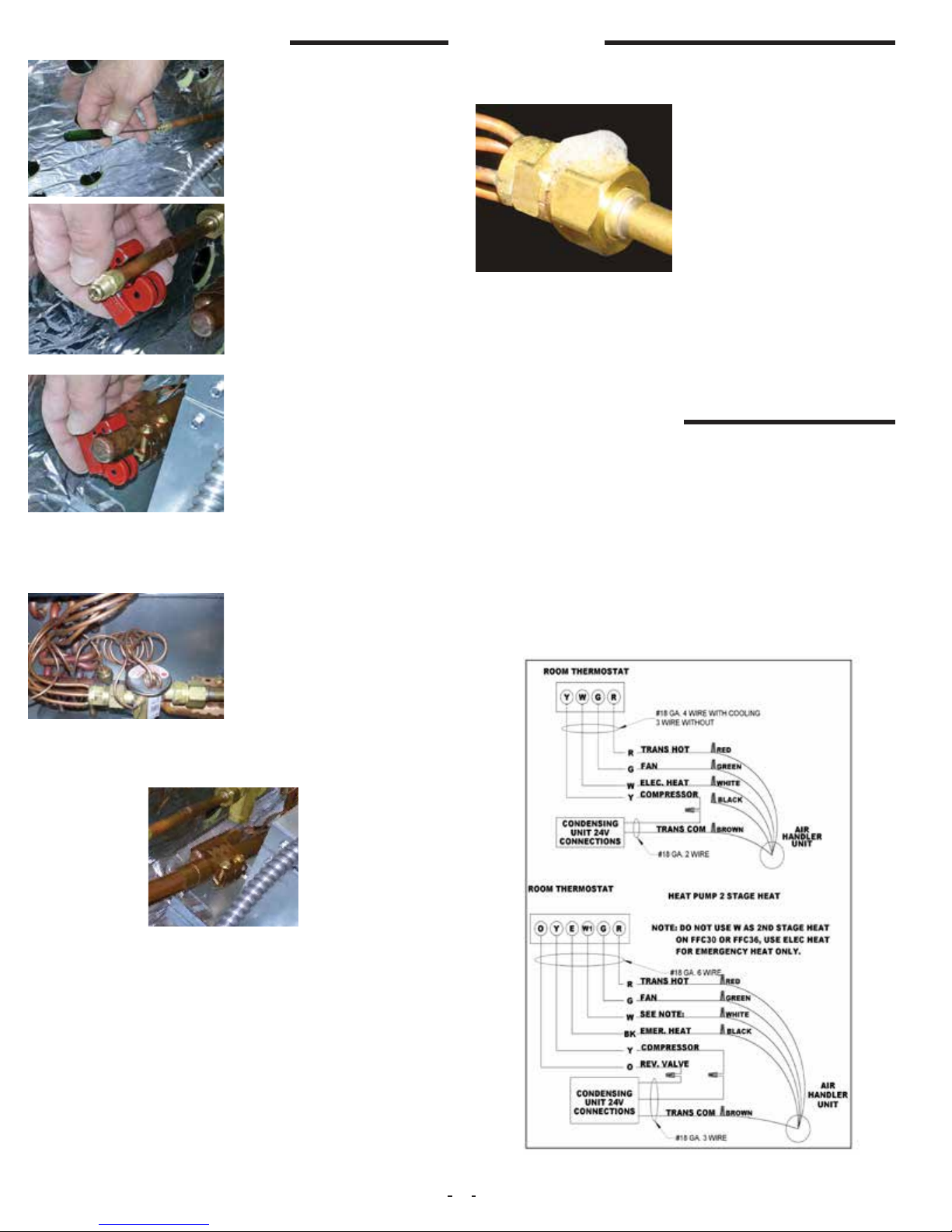
If the line voltage being supplied to the air handler is 208 volt single
phase, the line voltage tap on the low voltage transformer needs to
be moved from the 240 volt tap to the 208 volt tap. If this is not done,
the secondary output voltage of the transformer will be too low (Fig
11-3).
Fig 11-2.
Fig 11-3.
Final air volume adjustments should be made by referencing total
external static pressure (Table 11A-1).
Table 11A-1.
11A. Single Stage Cooling
During cooling mode operation, indoor blower wire “G” will energize
a time delay relay located on the control board inside the air han-
dler. After a short time delay period, the time delay relay will apply
240VAC to the motor via the “MTR“ terminal. (See Schematic Fig
20-1.) Fan time delay periods are 30 seconds ON delay and 120
seconds OFF delay.
The Y wire from the thermostat is not connected at the air handler.
This wire goes directly to the outdoor unit 24 volt wiring to turn on
the outdoor condensing unit when a call for cooling takes place. The
24 volt common for the outdoor unit circuitry is connected at the air
handler brown wire. (See Fig 11-1.)
The heater low voltage wiring terminal “W” is wired directly from the
thermostat to the air handler. The indoor blower, on a call for heat,
will ON delay for a period of 5 seconds. When the call for heat has
been satised, the indoor blower will have an OFF delay time period
of 60 seconds.
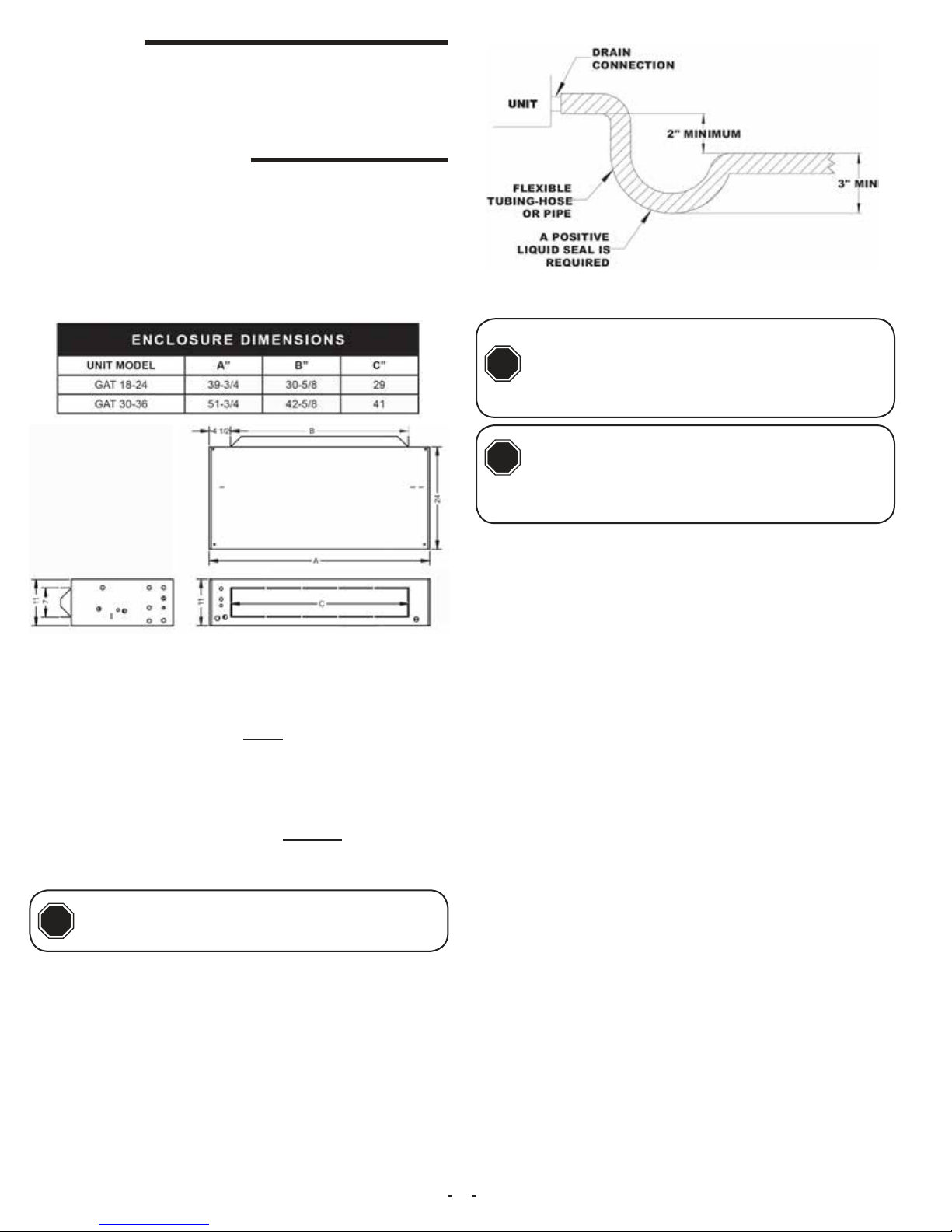
12. Condensate Drain
1. Select desired condensate drain openings according to air han-
dler orientation. Both Primary and Secondary outlets can be used.
2. Pipe condensate system using proper PVC ttings.
3. Ensure a minimum 2” trap is installed in the condensate drain. Lo-
cate the trap near to the connection opening on the air handler. See
illustration.
13. Air Volume Adjustment
Air volume needs to be set to the level recommended by the outdoor
unit equipment manufacturer. Most systems will require around 400
CFM of indoor air for every 1 ton of system cooling capacity. The air
volume must be set prior to attempting system charge.
This air handler uses a PSC type motor. The speed of this motor
is set by placing the appropriate winding lead wire on the “MTR”
terminal of the control board. Unused motor winding leads are to
be placed on the “BLANK” terminals on the control board. The air
volume level produced by the air handlers at varying external static
pressure levels is shown in Table 11A-1.
240VAC
Tap
208VAC
Tap
ELECTRIC H EAT KIT NOMENCLATURE
H C S 10
H = Fits GAS, GAT, GES*, GET* Power Connection
C = Circuit Breaker
L = Large Cabinet (42 - 61)
S = Small Cabinet (18 - 36)
Heat Strip
00 = NO Heat
03 = 3 KW
05 = 5 KW
06 = 6 KW
08 = 8 KW
10 = 10 KW
BLOWER DATA
UNIT MODEL RPM AMP VOLT HP CFM VS. STATIC PRESSURE
0.00 0.10 0.20 0.30 0.40
GAT 18
1625
1.4 240 1/4 850 775 700 675 600
GAT 24 1000 900 850 775 700
GAT 30 2.15 240 1/3 1200 1150 1100 1050 975
GAT 36 1600 1500 1400 1300 1200
HEATING AND COOLING PERFORMANCE & ELECTRICAL DATA
MODEL HEAT KIT
PERFORMANCE DATA ELECTRICAL DATA
NOMINAL
COOLING
(TONS)
HEATING
(KW)
HEATING
CAPACITY
(MBTUH)
MIN-CIRCUIT
AMPACITY
MAX FUSE OR
CIRCUIT
BREAKER
208V 204V 208V 204V 208V 204V 208V 204V
GAT 18
HCS00
1.5
0.0 0.0 0.0 0.0 1.9 2.3 15.0 15.0
HCS03 2.3 3.0 7.7 10.3 15.0 17.0 15.0 20.0
HCS05 3.8 5.0 13.0 17.1 24.0 29.0 30.0 30.0
HCS08 6.1 8.0 20.8 27.3 28.0 43.0 40.0 50.0
HCS10 7.6 10.0 25.9 34.1 47.0 54.0 50.0 60.0
GAT 24
HCS00
2.0
0.0 0.0 0.0 0.0 1.9 2.3 15.0 15.0
HCS03 2.3 3.0 7.7 10.3 15.0 17.0 15.0 20.0
HCS05 3.8 5.0 13.0 17.1 24.0 29.0 30.0 30.0
HCS08 6.1 8.0 20.8 27.3 28.0 43.0 40.0 50.0
HCS10 7.6 10.0 25.9 34.1 47.0 54.0 50.0 60.0
GAT 30
HCS00
2.5
0.0 0.0 0.0 0.0 2.0 3.0 15.0 15.0
HCS03 2.3 3.0 7.7 10.3 15.0 18.0 15.0 20.0
HCS05 3.8 5.0 13.0 17.1 25.0 29.0 30.0 30.0
HCS08 6.1 8.0 20.8 27.3 40.0 45.0 40.0 50.0
HCS10 7.6 10.0 25.9 34.1 49.0 55.0 50.0 60.0
GAT 36
HCS00
3.0
0.0 0.0 0.0 0.0 2.0 3.0 15.0 15.0
HCS03 2.3 3.0 7.7 10.3 15.0 18.0 15.0 20.0
HCS05 3.8 5.0 13.0 17.1 25.0 29.0 30.0 30.0
HCS08 6.1 8.0 20.8 27.3 40.0 45.0 40.0 50.0
HCS10 7.6 10.0 25.9 34.1 49.0 55.0 50.0 60.0
AIR H ANDLER C HASSIS N OMENCLATURE
G A T 18 G -001
AirMark
Air Handler
Voltage
A = 240V PSC Motor
B = 120V PSC Motor
Conguration
T = Cased Ceiling Mount
Nominal
Tonnage
(MBTUH)
Metering Device
4 = non-bleed A/C or H/P R410 TXV
6 = 20% bleed A/C or H/P R410 TXV
B = 20% bleed A/C or H/P R22 TXV
F = R-22 Flo-rater
G = R-410A Flo-rater
X = non-bleed A/C or H/P R22 TXV
Option Code
1. Select a speed tap from the CFM table and connect appropriate
motor lead wire to the “MTR“ terminal on the control board.
2. Call for fan only operation at the thermostat.
3. Read the external static pressure level on the Magnehelic gauge.
4. Make speed tap selection change to get the air volume as close
as possible to the required level.
5. If the static pressure is above .5” wc, excessive turbu-
lence or duct friction needs to be reduced. (Obstructions in
the duct system can also cause excessive static pressure.)
6. When proper air volume is established, move on to the charging
procedure.
Use a Magnehelic Gauge with a 1” scale and two static pressure
tips to measure the static pressure during the air volume adjustment
procedure. The high port static pressure tip should be placed in the
supply duct near the outlet of the air handler. The low port static pres-
sure tip should be placed in the return air duct near the entrance to
the air handler.
Use a Magnehelic Gauge with a 1” scale and two static pressure
tips to measure the static pressure during the air volume adjustment
procedure. The high port static pressure tip should be placed in the
supply duct near the outlet of the air handler. The low port static
pressure tip should be placed in the return air duct near the entrance
to the air handler. The factory provided air lter should be in place
inside of the air handler.
COM

10 IO-123114 Effective 12-04-2014
1. Bring airow up to the maximum CFM possible according to Table
11A-1.
2. Evacuate refrigeration system to micron level required by outdoor
unit manufacturer.
14. System Charging
An improperly charged system may cause
degradation in system performance and
damage the compressor. After installation
of the coil, refer to the outdoor unit manufacturer for charging
techniques and amount of charge. If outdoor unit manufacturers
charging instructions are unavailable, then refer to instructions
below to charge the system.
CAUTION
!
16. Start-Up
14B . Expansion Valve Coils
Add refrigerant until the subcooling measured at the outdoor unit
liquid line matches the subcooling recommendation of the outdoor
manufacturer (typically 7º – 10º F). If chart is unavailable refer to
Table 14B-1.
Table 14B-1.
After all connections are made, start-up and checkout must be per-
formed before proper evaluation of the entire system can be made.
Make sure that heat anticipator is properly set as noted on thermo-
stat instructions. Load requirements can vary in each residence and
it may be necessary for the installer or homeowner to make slight ad-
justments to the heat anticipator setting for longer or shorter cycles.
It is recommended to change the setting no more than plus or minus
0.05 amps at a time. Greater changes can cause the unit to rapid
cycle or remain on excessively.
15. Adjustment Of Heat Anticipator
14A . Flowrator Coils
Add refrigerant until the superheat measured at the outdoor unit suc-
tion/vapor line matches the superheat listed in Table 14B-1.
To properly check the unit’s operation, the installer should have an
electrical current measuring device (0-10 amp Amprobe, Fluke), air
pressure measuring device (0-1.0 in slope gauge), and a tempera-
ture-measuring device (0-200ºF thermometer).
3. Release system charge from outdoor unit and call for cooling.
4. Use outdoor unit equipment manufacturer specic charging charts
if available and make proper charge adjustment based upon outdoor
unit instructions.
5. If outdoor unit instructions and charts are not available, use Aspen
provided charts. Make certain indoor air temperature is near comfort
level setpoint of 75°F prior to establishing superheat and subcooling
levels.
Install the Amprobe to measure blower current, the slope gauge to
measure static air pressure at the units and the temperature device
to measure unit supply and return air temperature. Before taking
measurements, be sure that all registers, grilles and dampers are
open or set to their proper positions. Be sure that clean lters are
in place. Temperature measuring device must be installed to obtain
average temperature at both inlet and outlet. For outlet, measure
temperature of each main trunk at a location far enough away to
avoid heater radiation and read the average temperatures. Table
11A-1 shows the CFM that should be achieved at various external
static pressures
Turn on power supply. Set thermostat fan switch to on. Set the cool-
ing indicator to maximum, heating to minimum. System switch may
be on heat or cool. Check slope gauge measurement against appro-
priate air ow chart. Make damper, register and motor speed adjust-
ments to obtain required airow.
Set thermostat fan switch to auto, system to heat and thermostat
heating indicator to maximum heat. Blower should start and all heat
be energized.
Check air ow using temperature rise method.
17. Checking Air Flow/Temperature Rise Method
CFM
OUTPUT BTUH
TEMP RISE
=
•
()
..
108
NOTE: BTUH output should be computed by VOLT x AMPS x 3.4 =
BTUH OUTPUT. Since line volt can vary, do not use nameplate rat-
ing to determine output.

IO-123114 Effective 12-04-2014 11
Below are brief descriptions of the key components of the unit and in-
stallation. This manual only provides general idea of the components
and recommended practices. The installer should use best judge-
ment to ensure safe installation and operation of the unit.
1. Room Thermostat- This is the device that controls that operation
of your heating and/or cooling unit. It senses the indoor temperature
and signals the equipment to start or stop maintaining the tempera-
ture you have selected for your comfort. The room thermostat should
be in a central, draft free inside wall location for best operation. Do
not place any heat producing apparatus such as lights, radio, etc.,
near the thermostat as this will cause erratic operation of the comfort
system. The thermostat can accumulate dust or lint which can affect
its accuracy. It should be cleaned annually.
2. Air Filter(s) - All central air moving comfort systems must include
air lter(s). These lters will be located either in the equipment or in
the return air duct system upstream of the equipment. The lter(s)
removes dust and debris from the air thus helping to keep your air-
conditioned space clean. More important, the lter keeps dust and
debris from collecting on the heat transfer surfaces thus maintaining
18. Operation and Maintenance
4. a) Do not store combustible materials
or use gasoline or other ammable liquids
or vapors in the vicinity of this appliance.
b) Do not operate the comfort equipment with panels re-
moved.
c) Have your contractor point out and identify the various
cut-off devices, switches, etc., that serve your comfort
equipment. There is a main switch that will cut off energy to
your heating system. Know where they are so that you may
cut off the ow of energy in the event of overheating.
!WARNING
optimum equipment efciency and performance. Inspect and clean
or replace lters every month. This routine maintenance procedure
will pay big dividends in reduced operating cost and reduced service
expense. Never operate comfort equipment without lter(s).
3. Fuses and/or Circuit Breakers- This comfort equipment should be
connected to the building electric service in accordance with local
and National Electric codes. This electrical connection will include
over-current protection in the form of circuit breakers. Have your
contractor identify the circuits and the location of over-current protec-
tion so that you will be in a position to make inspections or replace-
ments in the event the equipment fails to operate.
19. Final System Checkout
1. Make certain all cabinet openings are properly sealed and any
grommets moved during installation are moved into proper place.
2. With cooling system operating, check for condensate leakage.
3. Perform leak detection inspection of refrigerant circuit and con-
necting piping.
4. Secure all cabinet doors.
5. Periodic Checkup and Service- This product is designed to pro-
vide many years of dependable, trouble-free comfort when properly
maintained. Proper maintenance will consist of annual check-ups
and cleaning of the internal electrical and heat transfer components
by a qualied service technician. Failure to provide periodic checkup
and cleaning can result in excessive operating cost and/or equip-
ment malfunction.
6. Lubrication- Direct drive blower motors are equipped with perma-
nently lubricated bearings and do not require further lubrication.
7. Air lter replacement: An air lter can restrict the airow of air to
the fan coil if it is not cleaned or replaced periodically. When replac-
ing the air lter, always replace with the same type and size as origi-
nally furnished with the unit.

12 IO-123114 Effective 12-04-2014
20. Wiring diagram for 00-10 kW heating GAT & GAS models
HIGH VOLTAGE disconnect all power sources prior to servicing. Failure might lead to safety hazard
NOTES :
1. LINE SPLICE TO BE ATTACHED TO UN USED
MOTOR LEAD. RD - LOW , BL - MED, BK - HI
2. RED WIRE TO BE ON TERMINAL 1 FOR 230 VOLT
OR TERMINAL 2 FOR 208 VOLT OPERATION.
WIRING CODE
FACTORY LOW VOLT
FIELD HIGH VOLT
FIELD LOW VOLT
FACTORY HIGH VOLT
DIAGRAM # 101074
EQUIPMENT GROUND
BK RD
1
2
3
4
5
6
7
9
BK
RD
LCHEATER 2
LC
HEATER 1
SEQUENCER
BK
RD
RD
WHBR
RD
RD
BK
BK
BK
BK
RD
RD
GR
RD
RD
MP
GR
BR
WH
BK
CIRCUIT BREAKER
POWER SUPPLY
USE COPPER
OR
THE EQUIVALENT
SEE RATING PLATE
HCS-03 HCS-04 HCS-08
1
23
FC
EM
BTD
HTR 1
HTR 2
LC
R
HS
BTD
WH
GNBR
TRANSFORMER
24 VOLTS
HTR 3
BK
CB CB
LC
LC
HS
LO SPEED
(CAPPED)
MED SPEED
(CAPPED)
HS HS
BLOWER MOTOR SPEED SETTING FOR MAX KW RATING
UNIT
MODEL
MAX
KW
SPEED
TAP
ELECTRIC HEAT
ONLY
ELECTRIC HEAT
& HEAT PUMP
MAX
KW
SPEED
TAP
GAS / GAT 18
GAS / GAT 24
06
06
LO
HI
06
06
LO
HI
TABLE 1
CURRENT 061614
208-240 VOLTS
HCS-10
GAS / GAT 36 10 HI 10 HI
GAS / GAT 30 10 LO 10 LO
WIRE HARNESS
127035
127032 x 2
COLOR CODE
LEGEND
BTD
CB
BM
FC
FS
- BLOWER TIME DELAY
- CIRQUIT BREAKER
- BLOWER MOTOR
- FAN CAPACITOR
- FEMALE SOCKET
W
BK
BL
RD
BK/W
GN
GR
BR
GN/BK
GN/RD
- WHITE
- BLACK
- BLUE
- RED
- BLACK/WHITE STRIPE
- GREEN
- GRAY
- BROWN
- GREEN/BLACK STRIPE
- GREEN/RED STRIPE
LC
HS
HTR
MP
- LIMIT CONTROL
- HEAT SEQUENCER
- HEATER
- MALE PLUG
213
5 4
SEE NOTE 2
8
SEQUENCER
WHBR
WBK
R BRGN W BK
1 2 3 4 5 6 7 89
BK R
24V (HOT)
FAN
ELECTRIC HEAT
EMERG. HEAT
24V (COM)
R
BK
GN BR W BK
W
R
CAPACITOR
BK R
SEE NOTE 1 AND TABLE 1
GN
EVAPORATOR
MOTOR
321
54
24V(COM) 24V
230V208VCOM
SEE NOTE 2
R
BR
GN

IO-123114 Effective 12-04-2014 13

14 IO-123114 Effective 12-04-2014
373 Atascocita Rd.
Humble, TX 77396
Phone: 281.441.6500
Toll Free: 800.423.9007
Fax: 281.441.6510
www.airmark-ac.com
© Copyright 2014 AirMark. All Rights Reserved
Revised 12/04/2014. Subject to change without notice and without incurring obligation.
This manual suits for next models
1
Table of contents
Popular Electric Heater manuals by other brands

Gabarron
Gabarron TBC 8 Installation instructions and user guide

Chromalox
Chromalox PF450-5 Installation Instructions and RENEWAL PARTS IDENTIFICATION

Vornado
Vornado VH110 owner's guide

Heatscope
Heatscope MHS-SM1600 Original installation and instruction manual

AKO
AKO WW 101 E Installation and operating instructions

Vortice
Vortice THERMOLOGIKA SKY Instruction booklet