13
GB
INTRODUCTION
This handbook is designed for the
customers, who bought a compressor for
hobby use and contains the necessary
information for the determination of the
model, for the installation, the use and the
maintenance.
The handbook is to be read carefully in order
to observe the instructions for use and
guarantee the effectiveness of the
compressor. Do not throw away the
handbook after reading it.
The compressors described in the handbook
are in conformity with the security and
bealth requirements under the directives of
the responsible authorities.
For further information, please contact our
technicians, who are at your disposal.
Technical interventions, leading to changes
in the structure of the compressor, are to
be quoted in this handbook. As
manufacturers we deny any responsibility
deriving from non-compliance with the
instructions of this handbook.
WARNING
This maintenance and operation
handbook is part of the compressor
system and is to be kept with the
compressor or by the persons in
charge of the system.
IMPORTANT NOTICE
In order to offer an efficient service
and to meet all the requirements of
our customers please specify the
model number that is indicated on the
test plate.
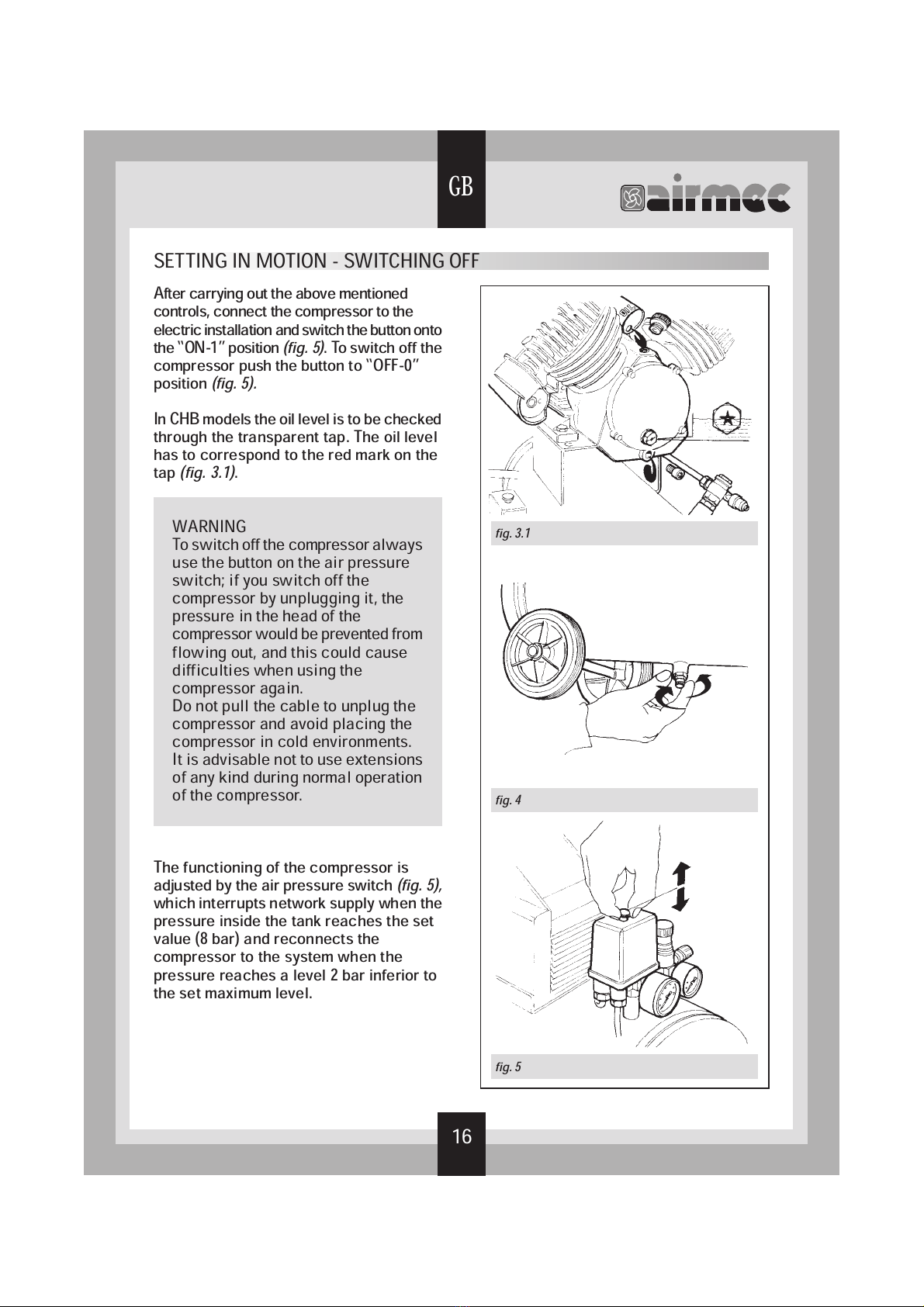
CONGRATULATIONS
Dear customer,
the choice of the professional compressor
proves your technical competence and your
love of beautiful designs.
Our products are made of high quality
components, which are checked in the
various stages of production and undergo
several tests, to guarantee that the
compressor meets the curstomer’s
requirements.
The electric compressor is safe and
versatile, and will last a long time, provided
the
operation and maintenance instructions
in the handbook are observed. The
handbook was written in compliance with
the EC engine directive 89/392.
Non-observance of the instructions might
compromise the correct functioning of the
compressor, and we would be forced
not to
apply the guarantee provisions and to deny
all responsibility for damage to persons,
animals or things.