Airpax Dimensions 24/4500H-3PH User manual

ISO 9001:2000 Certified Company
DC to AC Power Inverters
OWNERS MANUAL for Models:
24/4500H-3PH
24/6000H-3PH
Form 120015
OWNERS MANUAL JANUARY 2007
120015C
Airpax Dimensions, Inc.
4467 White Bear Parkway (651) 653-7000
St. Paul, MN 55110-7626 Fax (651) 653-7600

OWNERS MANUAL
INVERTER MODEL
24/4500H-3PH
24/6000H-3PH
Table of Contents
Page
1. General . . . . . . . . . . . 2
2. Description . . . . . . . . 2
3. Installation . . . . . . . . 2
4. Start Up/Operation. . . 4
5. Troubleshooting. . . . . 4
6. Installation Figure 1. . 5
7. Limited Warranty . . . . 6
1. GENERAL
1.01 Airpax Dimensions inverters have been
designed and manufactured for many user appli-
cations and long life. They utilize patented con-
struction methods and high technology electronic
parts and circuitry.
1.02 The inverter is powered by a 24 volt
auxilary battery. The remote On/Off control
circuitry requires + 12 volts to operate.
1.03
CAUTION:
Inverters produce hazardous
voltages,toavoid riskofharmorfiretheunitmust
be properly installed. There are no user service-
able parts inside, do not remove the cover.
CAUTION:
The inverter should not be mounted in
a location that may be exposed to rain or spray.
CAUTION:
The inverter should not be installed in
a zero clearance enclosure.
CAUTION:
Damage to the inverter will occur if
correctpolarityis notobservedwheninstallingthe
DC input cables.
CAUTION:
Damage to the inverter will occur if an
externalACpowersourceisappliedtotheinverter’s
AC output or it’s hardwire output.
CAUTION:
The inverter contains a circuit breaker
and capacitor that may produce a spark. Do not
mount in a confined battery or gas compartment.
CAUTION:
Working in the vicinity of lead-acid
battries is dangerous. Batteries generate explo-
sivegases during operation. There is a riskofacid
exposure. There is also a risk of high current
dischargefromshortingthebatterythatcancause
fire and explosion.
CAUTION:
Be sure the inverter is turned "OFF"
duringinstallation.
Page 2
2. DESCRIPTION
2.01 The inverters converts 24VDC to 220
VAC, 3 phase; or 220 VAC single phase; or 120
VAC,singlephase;allat60HZ,havinga quasi-sine
wave form.
2.02 The inverters have internal protection
against output short circuit, output overload and
high temperature conditions. Also, there are
thermally controlled cooling fans.
2.03 The inverters are designed to operate
almost any 60 HZ appliance, equipment or tool
withintheir voltage, phase and power ratings that
does not require a pure sine waveform.
3. INSTALLATION
3.01 The following instructions should be
thoroughly read and under.stood before installa-
tion.
3.02
CAUTION:
Inverters produce hazard-
ous voltage, and to avoid risk of harm or fire the
unit must be properly installed.
CAUTION:
Theinvertershouldnotbe mounted in
a location that may be exposed to rain or spray.
CAUTION:
The inverter should not be installed in
a zero clearance enclosure.
CAUTION:
When working near batteries, safety
goggles should be worn.
CAUTION:
Be sure the inverter is turned "OFF"
during installation.
NOTE:
Allwiring mustfollow theNationalElectric

IMPORTANT NOTE FOR VEHICLE
INSTALLATION:
Do not use the vehicle chassis
as the negative return in place of a return cable.
Usethesamesizecableasthe positiveconnection
and run directly to the battery.
3.05.5 Install the cables at the battery,
inverter and then fuse holder. Make sure that
clean, tight connections are made. Use care not
totouchthepositiveandnegativecablestogether.
A violent spark will result and could result in
exploding batteries and fire.
3.05.6 The battery input terminals are lo-
cated in the wiring compartment. A mounting
spark may result when connecting the battery
wire,duetoaninitialchargingoftheinternalinput
capacitor.
3.05.7
CAUTION:
Connecting the inverter
to the wrong polarity of the battery will cause
damage that is not covered under warranty.
3.06 Remote ON/OFF Switch - FIG. 1
NOTE: The inverterwillnotswitch on unless the
violet wire has +12 VDC applied to it.
3.06.1 All material used for the remote
switch should be U.L. listed and installed per low
voltage, Class 2, wiring code. The remote switch
hookup can not provide additional current to
operate a indicating lamp.
3.06.2 The remote switch should be single
pole and have at. least a 5 amp rating, such as
Leviton No. 1330-2. The wire used should be at
least 18 gauge.
3.06.3 The switch should be mounted at a
convenient location. in a listed outlet box with
approved strain relief.
3.06.4 The remote switch should be con-
nected to the violet wire marked “Remote Switch
Hookup” in the wiring compartment. Positive
(+)12 battery voltage must be connected to the
other side of the switch. Cable clamp strain relief
should be used to secure the field wires.
3.06.5 Units with a model designation
ending in "R24" have the remote On/Off switch
Page 3
Code,provincialorothercodesineffectatthetime
of installation, regardless of suggestions in this
manual. All wires should be copper conductors.
3.03 Mounting
3.03.1 Locate a suitable, secure flat mount-
ingsurfaceasclosetothe24voltauxilarybatteries
as possible without being in the same air tight
compartment. The maximum recommended dis-
tance between the mounting location and the
battery is 10 feet.
3.03.2The location should provide adequate
ventilation and clearance to maintain room tem-
perature while the unit is operating. At least 1/2
inch of clearance is required on all sides.
3.03.3 Secure the unit with 1/4" screws or
bolts in the mounting holes on the legs of the unit.
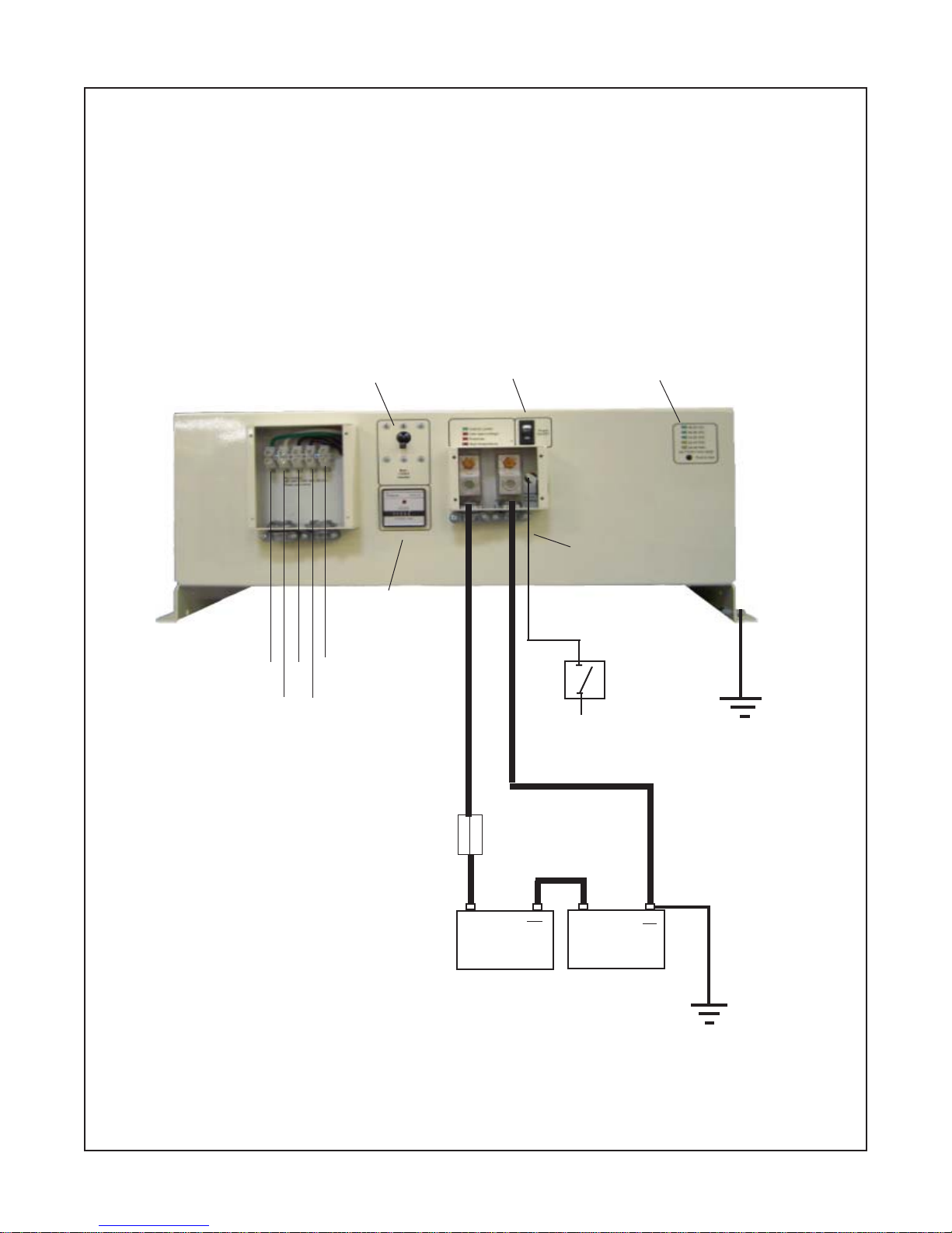
3.04 Chassis Bonding Lug - FIG.1
3.04.1 Connect a #8 gauge or greater wire
between the bonding lug on the inverter and the
system ground or vehicle chassis.
3.05 DC Wiring - FIG. 1
3.05.1
CAUTION:
Assure that hydrogen gas
does not accumulate near the battery by keeping
the area well ventilated. A spark may result when
connecting the final battery wiring due to initial
charging of the internal input capacitor.
3.05.2 Use stranded copper cable between
the battery and the inverter as indicated. Keep
the distance to less than 10 feet. A line fuse must
be installed between the battery and the inverter.
ULrequiresthatthefusebewithin18inchesofthe
battery.
Cable gauge Line fuse
24/4500H-3PH 3/0 500 amp
24/6000H-3PH 4/0 600 amp
3.05.3 Use only an approved fuse holder
with a U.L. listed fuse as indicated above.
3.05.4 Using smaller input cable or longer
length will greatly degrade the inverter peak per-
formance.

Page 4
circuitmodified to accept+24VDC instead of +12
VDC. The remote switch must be connected to
the violet wire marked "Remote Switch Hookup".
3.07 220Y/120 VAC Output
3.07.1
CAUTION:
Do not connect another
source of AC power directly to the output of the
inverter. This will result in damage to the inverter
that is not covered under warranty!
3.07.2 The A.C. output is presented at the
A.C. wiring compartment. The 3 phase outputs
are labeled “L1”, “L2”, “L3”. There is also an A.C.
neutral labeled “N” and a chassis ground labeled
“G”.
3.07.3 To obtain 220 VAC, 3 phase output,
a connection must be made to L1,L2, and L3.
3.07.4 To obtain 220 VAC, single phase
output, a connection should be made to any two
of the hot leads, as L1 and L2, or L1 and L3, or L2
and L3.
3.07.5 To obtain 120 VAC, single phase
output a connection. should be made to any one
hot lead and to AC neutral “N”; as L1 and N, or L2
and N, or L3 and N.
3.07.6Remote AC outlets should be mounted
at a convenient location in a listed outlet box with
approved strain relief, if used.
4. OPERATION
4.01 To operate the inverter, switch the
output circuit breaker switch to “ON”. Also switch
“ON”theinverteron/offswitchandtheremoteon/
off switch (if used).
5. TROUBLESHOOTING
5.01 Airpax Dimensions Unlimited, Inc. offers
free phone consultation concerning installation or
troubleshooting.CalltheCustomerServiceDepart-
ment at 800-553-6418 or 651-653-7000;
fax: 651-653-7600.
e-mail:[email protected]
NOTE: Since the inverter has a quasi-sine wave-
form, a TRUE RMS volt meter is required for an
accuarte reading. Other volt meters that use
averagingcircuitrywillgiveincorrectreadings.
5.02 If the inverter fails to operate, use the
following trouble-shooting procedure.
5.02.1 Connect a 100 watt light bulb to
each 120 VAC phase and disconnect all other
output wiring.
5.02.2 Make sure the inverter is “ON” and
the output circuit breaker is also “ON”.
5.03.3 Observe the fault indicating lights
on the front of the inverter.
a) If the low input voltage light is lit, turn
inverter “Off” for 5 seconds, then turn “On” again.
Ifthelightagainturnson,checkwiring,DCsource
voltage, battery condition and line fuse.
b) If the overload light is lit, check output
wiring for short circuit. Otherwise, the load is too
large for the power rating of the inverter.
c) If the high temperature light is lit, the
inverter must be left cool to 40 C (104 F). Check
to see that the inverter is not in a closed compart-
ment and that the fans are not blocked.
5.03.4 If the above steps are completed
and the inverter still will not operate satisfactorily
call Dimensions for a return authorization num-
ber.

3 PHASE INVERTER
FIGURE 1
Page 5
*+24 V for units with a model designation ending in "R24".
Customer supplied
On/Off Switch
Fuse
24 Volt Auxiliary Battery Pack
+ 12 VDC*
Ground L1 L3
Neutral L2
++
Violet wire
Output Cir-
cuitBreaker
RunningTime
Meter
BatteryVoltage
Indicators
On/OffSwitch

Limited Warranty Terms & Conditions
Page 6
SHIPPINGTERMS:F.O.B.St.PaulMinnesota. Freightprepaidandbilled,subjecttopriorcreditapproval.
MINIMUMORDER:$50.00NetPrice
LOSSORDAMAGE:Lossordamageintransitistheresponsibilityofthecarrier. Anyclaimshouldbefiledwiththe
deliveringtransportcompany. Invoice,BillofLadingandDeliveryreceiptwithdamagenotedthereinmustaccompany
anyclaimsforfreightdamage. ClaimsforshortageandlostshipmentsmustbemadeinwritingtoAirpaxDimensions,
St. Paul, MN within 10 days of date of shipment. Claims not reported within this time frame will not be honored.
PRICES:Pricesaresubjecttochangewithoutnotice. Allordersaresubjecttoacceptanceatthefactory. Wereserve
the right to invoice prices in effect at time of shipment.
TERMS:Net30 days withapprovedcredit,creditcardor C.O.D.
RETURNGOODSPOLICY
*NoreturnedmaterialswillbeacceptedwithoutanaccompanyingReturnedMaterialsAuthorizationNumber(RMA)
fromfactory.
*Creditwillbeissuedforreturnedgoodstotheoriginalpurchaserwithin60daysofpurchase,providedtheinverter
isreturnedtoDimensionsunusedandnotmounted. Theamount of credit will beissuedatDimensionsdiscretion
based on the condition of the product.
*Customer must be in good standing with Dimensions.
*Invertersthatarediscontinued,high-voltage(over24vdc),special-orderorusedareexcludedandwillnotbeeligible
for
credit. Non-inverter items such as cable assemblies, fuses and fuse holders, will not be eligible for credit
*SupportcomponentssuppliedbyDimensionsvendorswillbecoveredunderthatmanufacturer'screditreturnpolicy.
* Customer pays return freight.
PLEASESHIPFREIGHTPREPAIDAUTHORIZEDRETURNSTO:
Airpax Dimensions, Inc. / 4467 White Bear Parkway / St. Paul, MN 55110
LIMITED WARRANTY: Dimensions warrants to the original purchaser for use that the goods or any component
thereof manufactured by Dimensions will be free from defects in workmanship for a period of 1 year from the date
ofpurchase,providedsuchgoodsareinstalled,maintainedandusedinaccordancewithDimensionsandtheoriginal
manufacturer'swritteninstructions.
ComponentsnotmanufacturedbyDimensions,butusedwithintheassemblyprovidedbyDimensions,aresubjectto
thewarrantyperiodasspecifiedbytheindividualmanufacturerofsaidcomponent,providedsuchgoodsareinstalled,
maintainedandusedinaccordancewithDimensionsandthemanufacturer'swritteninstructions.
Dimensions sole liability and the Purchaser's sole remedy for a failure of goods under this limited warranty and for
any and all claims arising out of the purchase and use of the goods, shall be limited to the repair or replacement of
the goods that do not conform to this warranty. The return of the purchase price in cash is at the sole discretion of
Dimensions.
Toobtainrepairorreplacementserviceunderthelimitedwarranty,thepurchasermustcontactthefactoryforaReturn
MaterialAuthorization(RMA). Onceobtained,sendtheReturnMaterialAuthorizationNumberalongwiththedefective
part or goods to: Airpax Dimensions, Inc., 4467 White Bear Parkway, St. Paul, MN 55110, freight prepaid.
THEREARENOEXPRESSWARRANTIESCOVERINGTHESEGOODSOTHERTHANASSETFORTHABOVE. THEIMPLIED
WARRANTIESOFMERCHANTABILITYANDFITNESSFORPARTICULARPURPOSEARELIMITEDINDURATIONTOONE
YEARFROMDATEOFPURCHASE.
DIMENSIONSASSUMESNOLIABILITYINCONNECTIONWITHTHEINSTALLATIONORUSEOFTHEPRODUCT,EXCEPT
AS STATED IN THIS LIMITED WARRANTY. DIMENSIONS WILL IN NO EVENT BE LIABLE FOR INCIDENTAL OR
CONSEQUENTIALDAMAGES.
WARNING:LIMITATIONSONUSE:DimensionsproductsarenotintendedforuseinconnectionwithLifeSupport
SystemsandforAvionicuse. Dimensionsmakesnowarrantyorrepresentationinconnectionwiththeirproductsfor
suchuses
This manual suits for next models
1
Table of contents
Other Airpax Dimensions Inverter manuals

Airpax Dimensions
Airpax Dimensions 12Z8NV User manual

Airpax Dimensions
Airpax Dimensions MIL-24/2600Q User manual

Airpax Dimensions
Airpax Dimensions 12/800N User manual

Airpax Dimensions
Airpax Dimensions ADI-36/3200D User manual

Airpax Dimensions
Airpax Dimensions MIL-24X26UVQ User manual

Airpax Dimensions
Airpax Dimensions 12 User manual

Airpax Dimensions
Airpax Dimensions ADI-64/500 User manual