manuals.online logo
Brands
  1. Home
  2. •
  3. Brands
  4. •
  5. AIRSLED
  6. •
  7. Jack
  8. •
  9. AIRSLED MP3400-VS User manual

AIRSLED MP3400-VS User manual

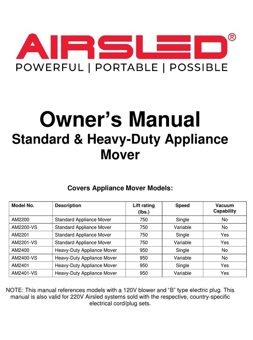
Owner’s Manual
3-IN-1 Multi-Purpose Mover
Covers 3-IN-1 Multi-Purpose Mover Models:
Model No.
Description
Lift rating
(lbs.)
Speed
Vacuum
Capability
MP3400
3-IN-1 Multi-Purpose Mover
2,300
Single
No
MP3400-VS
3-IN-1 Multi-Purpose Mover
2,300
Variable
No
MP3401
3-IN-1 Multi-Purpose Mover
2,300
Single
Yes
MP3401-VS
3-IN-1 Multi-Purpose Mover
2,300
Variable
Yes
MP3480
3-IN-1 Multi-Purpose Mover
2,300
Single
No
MP3480-VS
3-IN-1 Multi-Purpose Mover
2,300
Variable
No
MP3481
3-IN-1 Multi-Purpose Mover
2,300
Single
Yes
MP3481-VS
3-IN-1 Multi-Purpose Mover
2,300
Variable
Yes
NOTE: This manual references models with a 120V blower and “B” type electric plug. This
manual is also valid for 220V Airsled systems sold with the respective, country-specific
electrical cord/plug sets.
Page 1 of 8
70 –A Aleph Dr.
Newark, DE 19702
Support Email: [email protected]
Toll Free Number: 1-800-AIRSLED (1-800-247-7533)
SAFETY INSTRUCTIONS FOR USE
•Airsled systems can move countless objects provided that the appropriate conditions exist and that
the load’s weight is within the system’s maximum lifting capacity. These conditions include the
following:
✓Surface is level and free of incline and/or decline. DO NOT attempt using your Airsled system on
inclines, declines, ramps or stairs.
✓Surface is smooth and non-porous and free of debris. Porous surfaces such as carpeting requires
use of Airsled’s Rough Surface Adapters (RSAs).
✓Load’s weight is evenly distributed. If not the case, the air beams may need to be positioned in a
manner to help offset the uneven weight distribution (e.g. closer to the heavier side of the load).
✓Lower center of gravity is better. Attempting to move an object with a high center of gravity may
result in undesirable tilting when lifted leading to a tipping hazard. If moving an object with a high
center of gravity, ensure adequate support is present to offset any tilting.
•Keep all parts of the body, especially hands and feet, away from underneath the air beams and the
load being lifted while operating your Airsled.
•DO NOT stand or ride on the air beams.
•To avoid electric shock, do not use in damp or wet locations. Do not expose the blower to water or
other liquids. Use only grounded power cords and outlets.
AIRSLED 3-IN-1 MULTI-PURPOSE MOVER COMPONENTS
Qty
Description
3
Aluminum air beams*
1
Blower (may/may not have variable speed and/or vacuum capability
depending on model)
1
Shoulder strap
n/a
Vacuum cleaner nozzles and attachments for models with vacuum
capability
1
Tee connector
1
4-way connector
3
Supply hoses that connect to the air beams
1
Lead hose that connects to the blower
6
Rough Surface Adapters (RSAs)
6
Spacer sticks
1
Carrying bag for your complete system
BEFORE USING THE AIRSLED 3-IN-1 MULTI-PURPOSE MOVER
•Remove objects from the top and inside of the load you plan to move to prevent damage.
•Shut OFF or disconnect any gas, electric of water that may be connected to the load.
•Nonstructural features prone to bending near the load’s base such grill covers should be removed;
the air beams should only make contact with the load’s structural frame during movement.
•Verify that no other features or fixtures (e.g. hoses, drip pan, connectors, flanges) hang down from
the load’s base that may prevent the air beams from making contact directly with the structural frame.
•Because an Airsled will elevate the load, measure the overhead clearance between the highest point
of the load and any overhead objects such as cabinets or other overhangs. If less than 2”, please see
the Control and Maneuverability section.
•If your model has Variable Speed (VS) performance, you will be able to control the rate and height of
air beam inflation for greater control and safety in tight, overhead clearance situations.
Please see Exhibit 1 for
a detailed system
diagram to order
replacement parts.
Page 2 of 8
70 –A Aleph Dr.
Newark, DE 19702
Support Email: [email protected]
Toll Free Number: 1-800-AIRSLED (1-800-247-7533)
POSITIONING THE AIR BEAMS
•3N1 MP Mover air beams are 3/16” thick. There must be enough clearance between the floor and the
load’s base to allow the air beams to be freely slid into place. DO NOT force the air beams under the
load.
•If the gap between the air beam and load’s base is greater than 1 ½”, the air beams may not produce
the necessary lift. The included spacer sticks are ½” thick and may adequately bridge the gap. For
larger gaps, Airsled offers ADJUSTABLE SPACER SYSTEMS. More information on these items can
be found on www.Airsled.com. Wood blocking can also be used to bridge the gap.
•Slide the air beams under the load. See figure 1.
NOTE: The 3N1 MP Movers are adaptable to
countless loads of varying dimensions, weights
and footprints. Users will have to determine for
themselves, based on their specific load, the
optimal placement of the air beams to achieve
maximum Airsled performance. Figure 1 simply
shows one example of the air beam placement.
•3N1 MP Mover air beams are 12” wide x 39” long.
The load should ideally be centered over the air
beams for optimal Airsled performance. You may
need to adjust air beam placement several times
until the load maintains a level (non-tilting)
orientation once the air beams are inflated.
TIPS FOR AIRBEAM SELECTION AND PLACEMENT
Figure 1
The 3-IN-1 Multi-Purpose Mover is
designed for maximum versatility
and is ideal for loads that have
either unusual footprints or uneven
weight distribution. When evaluating
the 12x39 or 10x48 model, consider
the following to ensure optimal
performance.
You want to A) Position the air
beams so they are centered under
the lifting points and/or have as
much of the load as possible directly
over the air beams, and B) Minimize
extension of the front and rear of the
air beams past the load. The
diagrams to the left help illustrate
these points.
Page 3 of 8
70 –A Aleph Dr.
Newark, DE 19702
Support Email: [email protected]
Toll Free Number: 1-800-AIRSLED (1-800-247-7533)
Figure 4
CONNECTING THE AIRSLED COMPONENTS
•No tools are required to connect or disconnect the Airsled components. All connections between the
blower, lead hose, 4-way (or Tee) connector, supply hoses and air beam inlets should be done by
hand until a snug fit. See figure 2.
OPERATING YOUR AIRSLED
•Once the air beams are in position and all connections are snug, you are ready to plug your system
into a grounded electrical outlet.
•Strap the blower comfortably over your shoulder and engage the power switch. Alternatively, you can
position the blower on or attach it to the load if more convenient. See figure 1.
•BE PREPARED to brace and control the load once your Airsled system is activated. Using both
hands to control and maneuver the load at all times is recommended. See figure 1.
CONTROL AND MANEUVERABILITY
•All Airsled systems have an air flow controller. See figure 6. By fully opening the
controller, less air will flow into the air beams. This can help reduce the lift especially
in situations where overhead clearance is limited (e.g. less than 2”).
•When overhead clearance is less than 2”,the load may get “wedged” in place
once it is lifted by the air beams. Overhead with less than 2” clearance may also get
damaged when the load is lifted. If fully opening the air flow controller
does not resolve this issue, you can rapidly toggle the power switch
between the ON/OFF positions. This will partially inflate the air beams
allowing you to slowly move the load. WARNING –this toggle
approach requires two operators and should be done using extreme
caution to avoid injury or damage.
•Systems with dial-controlled, VARIABLE SPEED performance. (see
figure 4) can have the rate and height of air beam inflation controlled
making the load less likely to get wedged due to tight, overhead
clearance. If clearance is less than 1”, it is recommended you turn up
the air flow gradually.
•Tilting may occur if the load is not optimally positioned over the air beams. Excessive tilting may
lead to both suboptimal Airsled performance as well risk of injury and/or damage during the load
movement. When all three air beams are used, the operator will need to determine the best locations
for the air beams under the load to minimize tilting. It is common for two of the air beams to be
located under the area of highest weight distribution. Figure 5 illustrates the placement of the air
beams under a load with uneven weight distribution.
Figure 3
Figure 2
NOTE: When connecting or
disconnecting the supply
hoses to the air beams, do so
by grabbing the:
Solid hose end
Solid plastic inlet
Pulling only the soft hoses
may damage your system.
Page 4 of 8
70 –A Aleph Dr.
Newark, DE 19702
Support Email: [email protected]
Toll Free Number: 1-800-AIRSLED (1-800-247-7533)
GOING OVER POROUS SURFACES SUCH AS CARPETING
All Airsled systems come with plastic Rough Surface Adapters (RSAs). The RSAs are 10” wide x 36” long
and laid on top of the porous surface. The air beams MUST BE PLACED OVER THE RSAs in order for
your system to perform properly. See figure 6. Your system comes with 6 RSAs allowing you to create a
short track to move the load. If moving the load over long distances, heavy carboard paper such as Ram
Board®floor protection can be used. See figure 7.
CARE AND MAINTENANCE
Airsled systems are proudly made in the USA using the highest quality materials. If properly used and maintained,
your Airsled product will have a long service life. To ensure optimal performance and longevity, we recommend the
following:
•Keep the edges of the air beams from striking hard objects.
•When moving or repositioning the air beams, avoid dragging the corners.
•Avoid lifting and carrying the air beams by the inlets. Carrying the air beams by only the inlets may
cause them to come loose over time.
•Periodically inspect the blower filter and bag depending on model. These components should be
cleaned to ensure peak performance of the system’s blower.
•Check the rubber fabric for rips and dirt. If dirty, water with a mild detergent can be used to clean
them as well as household cleaning sprays such as Windex®. To restore the rubber fabric’s shine,
Armor All®is recommended.
•If you find any rips in the fabric, please see the Repairs and Refurbishment section.
Figure 5
Figure 6
Figure 7
Page 5 of 8
70 –A Aleph Dr.
Newark, DE 19702
Support Email: [email protected]
Toll Free Number: 1-800-AIRSLED (1-800-247-7533)
REPAIRS AND REFURBISHMENT
Wear and tear over time especially with frequent use may cause components to fail. Airsled offers
refurbishment services that can restore your aluminum air beams to as-new condition. More information
can be found on www.Airsled.com. Due to safety and regulatory concerns, Airsled cannot refurbish the
blower. Airsled also sells replacement parts. Please see detailed parts list in Exhibit 1. Any repairs
performed by the end-user should be considered temporary. We recommend contacting Airsled to
determine the proper course of action based on the nature of the issue. Some common, temporary
repairs that can be performed in the field include:
Rips in the rubber fabric. Small rips can be temporarily repaired with duct or electrical tape. Before
applying tape, the area must be cleaned and dried. We recommend returning your air beams to
Airsled to be fully refurbished if rips are discovered.
Cracked hose inlet. If you notice a crack in the plastic inlet connected to the air beam, you can wrap
the outer edge in tape after the surface has been cleaned and dried. We recommend that you replace
the inlet which Airsled sells.
Loose hose connections. Over time, the soft ends of the hoses may become stretched out causing
them to lose their snug fit. You can temporarily wrap the male ends with tape to establish a tighter
seal. We recommend that you replace the hoses which Airsled sells.
Page 6 of 8
70 –A Aleph Dr.
Newark, DE 19702
Support Email: [email protected]
Toll Free Number: 1-800-AIRSLED (1-800-247-7533)
Exhibit 1: Parts Diagrams
Models: MP3400, MP3400-VS, MP3480, MP3480-VS
Model: MP3401, MP3401-VS, MP3481, MP3481-VS
ID
Qty
Part No.
Description
A1
1
PA01OF
On/Off toggle switch
A2
1
PA01VS
On/Off variable speed dial (not
shown in diagram)
B
1
PA00CA
Front end cap
C
1
PA01PC
Power cord
D
1
PA00CF
Rear end cap and filter set
E1
3
PA1239
12” W x 39” L x 3/16” T air beams
E2
3
PA1048
10” W x 48” L x 3/16” T air beams
(not shown in diagram)
F
3
PA3INL
Hose inlet with damper gasket
G
1
PA4WAY
4-Way connector
H
1
PA3WAY
Tee connector
I
1
PA01LH
Lead hose
J
3
PA03SH
Supply hose
K
6
PA4RSA
Rough Surface Adapters
L
1
PA01ST
Shoulder strap
M
1
PA02BG
Carry bag for full system
N
6
AC32SS
Spacer sticks
-
1
PA3721
&
PA3721-
VS
Complete blower for MP3400
•4HP / 120v / 10.7 amps
ID
Qty
Part No.
Description
A1
1
PA01OF
On/Off toggle switch
A2
1
PA01VS
On/Off variable speed dial (not
shown in diagram)
B
1
PA00CA
Front end cap
C
1
PA01PC
Power cord
D
1
PA03CA
Rear end cap
E
1
PA04FB
Filter/bag
F1
3
PA1239
12” W x 39” L x 3/16” T air beams
F2
3
PA1048
10” W x 48” L x 3/16” T air beams
(not shown in diagram)
G
3
PA3INL
Hose inlet with damper gasket
H
1
PA4WAY
4-Way connector
I
1
PA3WAY
Tee connector
J
1
PA01LH
Lead hose
K
3
PA02SH
Supply hose
L
6
PA4RSA
Rough Surface Adapters
M
1
PA02ST
Shoulder strap
N
1
PA02BG
Carry bag for full system
O
6
AC32SS
Spacer sticks
P
n/a
n/a
Vacuum nozzle and hose
attachments
-
1
PA3751
&
PA3751-
VS
Complete blower for AM2401
•4HP / 120v / 10.7 amps
B
E1
A
C
D
F
G
H
I
J
K
L
M
N
A
B
C
D
E
G
F1
H
I
O
J
L
M
N
P
Note:
4HP 220v blowers are 5.7 amps
Note:
4HP 220v blowers are 5.7 amps
Page 7 of 8
70 –A Aleph Dr.
Newark, DE 19702
Support Email: [email protected]
Toll Free Number: 1-800-AIRSLED (1-800-247-7533)
LIMITED PRODUCT WARRANTY
Airsled, Inc. (warrantor) uses the utmost care in the manufacturing of its products and this is warranted to
be free from defects in material and workmanship, subject to the following limitations, qualifications and
conditions.
IDENTITY OF PARTY COVERED BY WARRANTY
This warranty extends only to the first customer purchaser and not to any subsequent transferee.
DESCRIPTION AND IDENTIFICATION OF PRODUCT
This warranty covers the following products of the warrantor; 3-IN-1 Multi-Purpose Movers.
WARRANTY STATEMENT
Airsled, Inc. (warrantor) offers a thirty-day money back satisfaction warranty from the date of purchase,
excluding all shipping costs. In the event of a defect, malfunction or failure to conform to this warranty, the
warrantor, at its election, will replace or repair such merchandise, including parts and labor, the warrantor
shall provide return labels. Defects, malfunctions, failure or damage to the product caused by improper
unreasonable or negligent abuse are specifically excluded from this warranty. In the event any repair or
modification is done to this product during the term of the warranty by anyone other than the Warrantor,
the defect applicable to such repair or modification shall be specifically excluded from this warranty, and
Warrantor, in its sole operation, may determine if this exclusion shall be applicable. This warranty shall
not apply to expendable parts, filters and the finish of painted parts. If products are returned within the 30-
day period with visible signs of heavy usage and/or damage, Airsled reserves the right to withhold 15% of
the purchase price to cover repair and refurbishment costs.
TERM OF WARRANTY
This warranty shall extend for a period of one (1) year from the date of original purchase by the first
consumer purchaser but shall expire prior thereto if the same shall be transferred to another person.
TO OBTAIN PERFOMANCE OF WARRANTY
To obtain performance of this warranty obligation, the eligible consumer must deliver the defective
product, with shipping and delivery charges prepaid, to:
Airsled, Inc.
70-A Aleph Dr.
Newark, DE 19702
Attn: Customer Service Dept.
The eligible consumer should also provide satisfactory evidence of the purchase date. In the event the
defect involves a not too labor intensive or costly correction, the warrantor shall replace or repair the
product and return the same to the consumer, with all return shipping and delivery charges prepaid.
LIMITATION ON REFUND
The Warrantor reserves the right to elect a refund in lieu of repair or replacement of the product provided
the Warrantor is unable to provide replacement and repair is not commercially practical or cannot be
timely made.
EXCLUSION OF ALL OTHER WARRANTIES
Other than as expressly provided herein, warrantor makes no other warranty express or implied with
respect to the product sold. Warrantor makes no warranty of product merchantability and no warranty of
fitness of the product for a particular purpose.
EXCLUSION OF INCIDENTAL OR CONSEQUENTIAL DAMAGES
Page 8 of 8
70 –A Aleph Dr.
Newark, DE 19702
Support Email: [email protected]
Toll Free Number: 1-800-AIRSLED (1-800-247-7533)
This warranty extends only to repair or replacement of the product and does not afford any coverage with
respect to incidental or consequential damages, nor shall any claim be greater in amount than the
purchase price of the product to which such claim is made. (Some states do not allow the exclusion or
limitation of the incidental or consequential damages so that the above limitation or exclusion may not
apply to you.)
ADDITIONAL RIGHTS
This warranty gives you specific legal rights and you may also have other rights which vary from state to
state.
AIRSLED, INC.
This warranty is intended to comply with Federal Legislation relating to the contents and terminology in all
warranties and shall be construed in a manner of consistent therewith.

This manual suits for next models

7

Other AIRSLED Jack manuals

AIRSLED AM2200 User manual

AIRSLED

AIRSLED AM2200 User manual

AIRSLED LiftCart User manual

AIRSLED

AIRSLED LiftCart User manual

AIRSLED VM1200 User manual

AIRSLED

AIRSLED VM1200 User manual

Popular Jack manuals by other brands

Draper 28497 Original instructions

Draper

Draper 28497 Original instructions

Gigant 13646-0102 Installation and operating instructions

Gigant

Gigant 13646-0102 Installation and operating instructions

Clarke Strong-Arm CTJ2500QLP Operation & maintenance instructions

Clarke

Clarke Strong-Arm CTJ2500QLP Operation & maintenance instructions

SFA OMEGALIFT 23221C Operating instructions & parts manual

SFA

SFA OMEGALIFT 23221C Operating instructions & parts manual

Sealey Quality MACHINERY TJ1000F instructions

Sealey

Sealey Quality MACHINERY TJ1000F instructions

Daytona DJS3TBK Owner's manual & safety instructions

Daytona

Daytona DJS3TBK Owner's manual & safety instructions

Omega Lift Equipment GQ025L manual

Omega Lift Equipment

Omega Lift Equipment GQ025L manual

Motomaster 009-1534-6 instruction manual

Motomaster

Motomaster 009-1534-6 instruction manual

ATD Tools 7345B owner's manual

ATD Tools

ATD Tools 7345B owner's manual

Motomaster 009-1535-4 instruction manual

Motomaster

Motomaster 009-1535-4 instruction manual

Esco 10771 instruction manual

Esco

Esco 10771 instruction manual

TMG TMG-AJS03 product manual

TMG

TMG TMG-AJS03 product manual

Urrea 2489 manual

Urrea

Urrea 2489 manual

CLAS B.LINE OH 5302BL manual

CLAS

CLAS B.LINE OH 5302BL manual

King Tony 9TY137 Operation manual

King Tony

King Tony 9TY137 Operation manual

Powerbuilt Ujack Operating and maintenance instruction manual

Powerbuilt

Powerbuilt Ujack Operating and maintenance instruction manual

CP CP9203 Instruction manual/safety instruction

CP

CP CP9203 Instruction manual/safety instruction

Sealey RJA1450 instructions

Sealey

Sealey RJA1450 instructions

manuals.online logo
manuals.online logoBrands
  • About & Mission
  • Contact us
  • Privacy Policy
  • Terms and Conditions

Copyright 2025 Manuals.Online. All Rights Reserved.