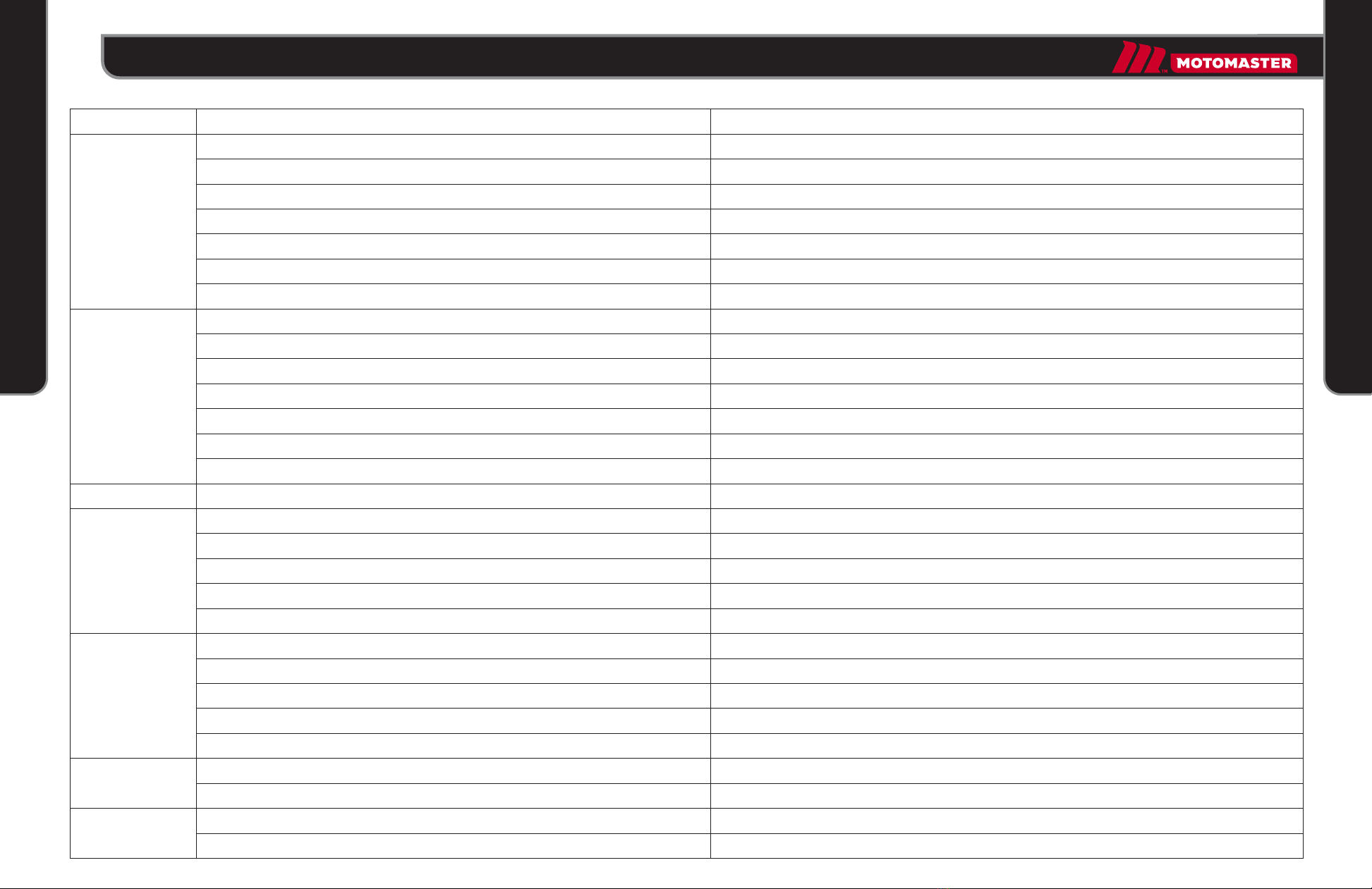
Motomaster 009-1535-4 User manual

2-IN-1 JACK/INFLATOR
INSTRUCTION
MANUAL
model no. 009-1535-4
IMPORTANT:
Please read this manual carefully before operating this jack/inflator
and save it for future reference.

SAFETY WARNINGS
1
2
3
4
5
6
7
8
9
Read all instructions, warnings and cautions provided with and on this unit. Make sure to
understand all instructions before operating this unit.
Failure to heed these warnings may result in electric shock, fire, and/or serious personal
injury.
The unit is heavy [10 lb (4.5 kg)]. Always carry it by the handle. Do not lift using the
pressure rod.
To avoid risk of fire, burns, personal injury and electric shock the unit should not be
played with or placed where children can reach it.
Never expose the unit to rain, frost, snow, moisture, or temperatures below -4 ºF (-20 ºC).
Inspect the unit before use. Do not use if cracked, broken or damaged parts are found.
Have the unit repaired or replaced by a qualified technician.
Do not use the jack on surfaces that are not capable of sustaining the load.
This jack is designed for use only on hard, level surfaces. Use on surfaces other than
those specified here can result in jack instability and possible loss of load.
This unit is for lifting the vehicle only. Immediately after lifting, support the vehicle with
appropriate means.
Use only the supplied accessories. Use of an attachment not recommended or sold by
manufacturer of this unit may result in a risk of fire, electric shock, or injury to persons.
2model no. 009-1535-4 | contact us 1-888-942-6686 3
DANGER: People with electronic devices, such as pacemakers, should consult
their physician(s) before using this product. Operation of electrical equipment in
close proximity to a heart pacemaker could cause interference or failure of the
pacemaker.
DANGER: This product contains chemicals known to cause cancer and birth
defects or other reproductive harm. Wash hands after handling.
WARNING: Not for continuous use. Allow the unit to cool for 10 minutes after
10 minutes of continuous operation.
WARNING: Do not run vehicle while the unit is operating. Engine must be
turned off.
DANGER: Do not crawl or reach underneath the vehicle during lifting or after
vehicle has been lifted off the ground.
WARNING: Do not attempt to lift more weight than this unit is rated for.
Repetitive overloading may cause damage to the unit.
WARNING: Do not leave this unit unattended during or after operation. Lower
the vehicle to the ground and turn off the unit before leaving the site.
WARNING
WARNING

12
13
UP
DOWN JACK
OFF OFF
FEATURES
OPERATION
Jack Function
1
2
3
4
2
1
3
4
5
6
7
8
9
10
11
12
13
Jack/Inflator and Off Switch
Jack Up/Down and Off Switch
Pressure Gauge
Threaded Rod
Protective Pad
Air Hose and Accessories Storage
Base Plate
Safety Value Cap
Handle
12 V Cord Storage
Rubber Foot
Ball/Ballon Adaptor, Spare Fuse and Hex Wrench
Two-stage Telescopic Ram
Make sure both switches on the unit are set to the Off (middle) position.
Press the locking tab inward and swing open the lid of power cord storage on the
side of the unit and remove the power cord.
Insert the power cord plug into the vehicle’s 12 V automotive outlet. Make sure the
red LED indicator on the plug turns on.
Place the jack on a flat, level and solid surface under the vehicle lifting point.
Align the jack saddle with the lifting point and rotate the saddle threaded rod to bring
the saddle closer to the lifting point on the vehicle’s frame.
Set the Inflator/Jack switch to the Jack position and set the jack Up/Down switch to
the Up position to start the jack.
IMPORTANT
Before operating the jack, pull the vehicle over to a secure location.
Shut the engine off, put the vehicle transmission in the Park position and pull
the emergency brake all the way.
45
model no. 009-1535-4 | contact us 1-888-942-6686
OPERATION
FEATURES

Inflator Function
1
1
2
3
4
2
3
4
5
6
7
8
9
10
5
6
7
8
Make sure both switches on the unit are set to the Off (middle) position. Press the
locking tab inward and swing open the lid of power cord storage on the side of the
unit and remove the power cord. Insert the power cord plug into the vehicle’s 12 V
automotive outlet. Make sure the red LED indicator on the plug turns on.
Press the locking tab inward and swing open the lid of inflator hose storage on the
side of the unit and remove the hose.
For inflating vehicle tires, remove the cap from the tire threaded inlet air valve stem
and securely screw the inflator hose connector into the valve stem.
For inflating other objects without the inlet air valve stem, attach desired adaptors to
the hose connector. Insert it inside the air inlet valve of the inflatable object.
Set the Inflator/Jack switch to the inflator position to start the inflator.
Inflate the object to the desired pressure while monitoring the pressure level on the
pressure gauge.
After inflating the object, set the Inflator/Jack switch to the Off (middle) position to
stop the inflator.
Remove the inflator hose from the object, and reattach the cap over the car tire's
threaded inlet valve stem.
Wrap inflator hose into a circle and store the hose in its storage.
Disconnect the power cord from vehicle’s 12 V outlet, wrap the cord into a circle and
store in its storage.
Remove the hex wrench from the accessory storage located on the side of the unit.
Remove the rubber cap over the safety valve on the top of the unit to be able to
access the safety valve hex cap screw.
Insert the hex wrench inside the safety valve hex cap screw and turn the wrench
counter-clockwise to loosen screw.
After jack is lowered, re-tighten the safety valve cap screw and replace the rubber
cap over the safety valve and store the wrench inside the accessory storage.
OFF OFF
INFLATOR
Allow the jack to lift the vehicle until the wheel(s) are slightly off the ground.
Set the Inflator/Jack switch to Off (middle) position.
After servicing the vehicle, set the jack Up/Down switch to the Down position to
lower the vehicle.
When jack is completely lowered, set the jack Up/Down switch and Inflator/Jack
switch to the Off (middle) position.
Disconnect the power cord from vehicle’s 12 V outlet, wrap the cord into a circle and
store in its storage.
OPERATING THE JACK SAFETY VALVE
In a rare occasion when jack’s ram is stuck at UP position and does not come down when
setting the UP/DOWN switch to DOWN position, perform the following:
67
model no. 009-1535-4 | contact us 1-888-942-6686
OPERATION
OPRTATION

TROUBLESHOOTING
Problem
The hose nozzle is not properly attached to the inflatable object.
The inflator hose or inflatable object has a hole, allowing air to escape.
The tire is completely deflated and has separated, allowing air to escape.
The vehicle’s battery voltage is too low.
The inflator has been running too long.
The inflator hose is damaged or is leaking.
The hose connector is not properly connected to the inflatable object air inlet.
The inflator has been running too long.
Refer to vehicle’s operating manual for fuse replacement instructions.
Recharge/replace the battery.
Secure the nozzle to the object.
Repair the hose or object.
Jack up the vehicle to release tire under vehicle’s pressure.
Recharge/replace the battery.
Rest the unit for 15–20 minutes.
Repair the hose.
Secure the nozzle to the object.
Rest the unit for 15–20 minutes.
Does not power on.
The inflator is running but
inflator does not inflate
the object.
The inflator takes too long.
Load is too heavy.
The jack is leaking hydraulic fluid internally.
The jack has not been used for a long time and needs to be cycled.
The safety valve screw is loose.
The jack Up/Down switch is set to incorrect position.
The vehicle’s battery voltage is too low.
The jack has been running too long.
The jack is leaking hydraulic fluid internally.
Ambient temperature is too low causing jack’s hydraulic fluid to thicken.
The safety valve screw is loose.
The load is too heavy.
The jack has been running too long.
The Inflator/Jack switch is set to either Off or Inflator position.
The ram is stuck.
Reduce the load by relocating the jack to a different lifting point on the vehicle.
Unit is defective. Call customer service.
Set the jack Up/Down switch to up and then Down position a few times.
Tighten the release valve screw.
Set the switch to the correct position.
Recharge/replace the battery.
Rest the unit for 15–20 minutes.
The unit is detective. Call customer service.
Warm up the unit for 1 hour.
Tighten the safety valve screw.
Reduce the load by relocating the jack to a different lifting point on the vehicle.
Rest the unit for 15–20 minutes.
Set the switch to jack position.
Loosen the safety valve screw to allow the ram to come down.
The jack motor is running
but jack does not operate.
Only the first stage of
jack’s telescopic ram rises.
The jack ram does not come
down when jack switch is set
to down position.
The jack takes too long to
lift the load.
89
Possible Cause Solution
The two switches on unit are not set to correct positions.
The power cord is not connected securely to the vehicle’s 12 V outlet.
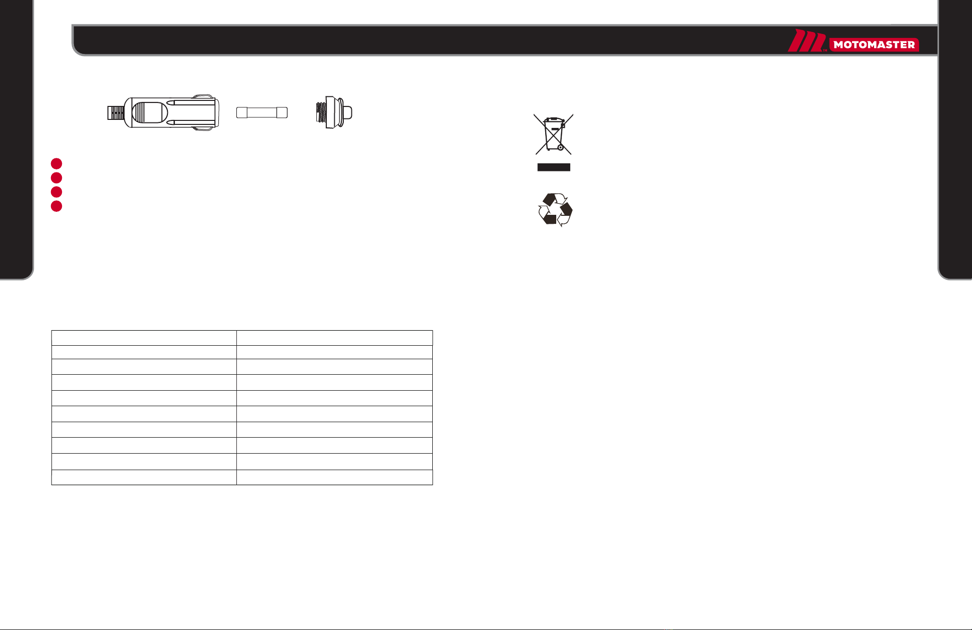
The LED indicator on the power cord plug is off. The power cord internal fuse is blown.
The power cord is damaged.
The vehicle’s 12 V outlet is dirty.
The vehicle’s 12 V outlet protective fuse is blown.
The vehicle’s battery is dead.
Set the switches to their correct positions.
Press the plug inside the outlet and make sure the LED indicator on power cord plug is on.
Replace the fuse.
Have a qualified service person repair cord.
Clean the outlet.
model no. 009-1535-4 | contact us 1-888-942-6686
TROUBLESHOOTING
TROUBLESHOOTING

SPECIFICATIONS
Input Voltage DC 12 V
Max. Loading Car Weight 6000 lb (2722 kg)
Max. Lifting Capacity 1 TON (907 kg) MAXIMUM WEIGHT
Lifting Height Range 5 1/4 to 14" (13.3 to 35.6 cm)
Max. Pressure 120 PSI
Length of Power Cable 11' (3.4 m)
Length of Air Hose 27 1/2" (70 cm)
Adaptors Ball/Balloon adaptor, spare fuse, hex wrench
ENVIRONMENTAL PROTECTION
Do not dispose of this product in the usual household garbage at the end of
its life cycle; hand it over at a collection point for the recycling of electrical
and electronic appliances. The symbols on the product, the instructions for
use or the packing will inform about the methods for disposal.
The materials are recyclable as mentioned in its marking. By recycling, material
recycling or other forms of re-utilization of old appliances, you are making an important
contribution to protect our environment.
Made in China
Imported by MotoMaster Canada Toronto, Canada M4S 2B8
WARRANTY
This MotoMaster product carries a one-(1)-year warranty against defects in workmanship
and materials. This product is not guaranteed against wear, breakage or misuse. Should
this product become defective within the stated warranty period, return it to the store
with proof of purchase, and it will be replaced or repaired free of charge.
Weight
Fuse
10 lb (4.5 kg)
15 A
Dispose of hydraulic oil in accordance with local regulations. Pouring oil onto
the ground or into storm drains, or tossing it into trash cans, even in a sealed
container, is illegal and can contaminate and pollute the environment.
1
2
3
4
Get a new fuse from the storage, and remove the black rubber case.
To replace the fuse in the plug, twist off the upper cover.
Remove the faulty fuse and insert a new one.
Twist the upper cover back on the plug.
FUSE REPLACEMENT
15 A 250 V
CLEANING
Use only mild soap and a damp cloth to clean the unit. Never let any liquid get inside the
casing. Never immerse any part of the unit in a liquid. Always keep the ventilation
openings clear.
10 11
model no. 009-1535-4 | contact us 1-888-942-6686
SPECIFICATIONS
ENVIRONMENTAL PROTECTION
Table of contents
Other Motomaster Jack manuals