AirStage UTY-DCGY User manual

INSTALLATION MANUAL
For authorized service personnel only.
CENTRAL REMOTE
CONTROLLER
English
PART NO. RCIM111207
UT Y- DCGY
UT Y- DCGG

En-1
INSTALLATION MANUAL
CENTRAL REMOTE CONTROLLER
SAFETY PRECAUTIONS1.
The “SAFETY PRECAUTIONS” indicated in the manual▪
contain important information pertaining to your safety.
Be sure to observe them.
For details of the operation method, refer to the operat-▪
ing manual.
Request the user to keep the manual on hand for future▪
use, such as for relocating or repairing the unit.
WARNING
This mark indicates procedures
which, if improperly performed,
might lead to the death or serious
injury of the user.
Perform electrical work by an authorized service
personnel in accordance with the installation manual
and the electrical wiring regulations or implementation
regulations of the country. Also do not install this unit
by yourself. Improper electric work will cause electric
shock or a re.
Perform installation work in accordance with the instal-
lation manual. Request an authorized service person-
nel to perform installation work. Do not install this unit
by yourself. Improper installation will cause injury,
electric shock, re, etc.
In the event of a malfunction (burning smell, etc.), im-
mediately stop operation, turn off the electrical break-
er, and consult authorized service personnel.
Install a leakage circuit breaker to power supply cable
in accordance with the related laws and regulations
and electric company standards.
Use a power source exclusively for this unit. Never
share the power source with indoor unit or other elec-
trical equipment. Doing so will cause re and electric
shock.
WARNING
This mark indicates procedures
which, if improperly performed,
might lead to the death or serious
injury of the user.
Do not install the unit in the following areas:
Do not install the unit near a source of heat, steam,▪
or ammable gas.
Area lled with mineral oil or containing a large ▪
amount of splashed oil or steam, such as a kitchen. It
will deteriorate plastic parts, causing the parts to fail
or the unit to leak water.
Area that generates substances that adversely affect▪
the equipment, such as sulfuric gas, chlorine gas,
acid, or alkali. It will cause the copper pipes and
brazed joints to corrode, which can cause refrigerant
leakage.
Area containing equipment that generates elec-▪
tromagnetic interference. It will cause the control sys-
tem to malfunction, and cause erroneous operation.
Area that can cause combustible gas to leak, con-▪
tains suspended carbon bers or ammable dust, or
volatile inammables such as paint thinner or gaso-
line. If gas leaks and settles around the unit, it can
cause a re.
Do not use the unit for special purposes, such as▪
storing food, raising animals, growing plants, or
preserving precision devices or art objects. It can de-
grade the quality of the preserved or stored objects.
Install the unit in a well-ventilated place avoiding▪
rains and direct sunlight.
Do not operate this unit when your hands are wet.
Touching the unit with wet hands will cause an electric
shock.
When children can approach the unit or touch the unit,
take preventive measures.
CAUTION
This mark indicates procedures
which, if improperly performed, might
possibly result in personal harm to the
user, or damage to property.
Pay abundant care when transporting this unit be-
cause it is a precision device. Improper transportation
will cause trouble.
Do not touch the switches with sharp objects. Doing so
will cause injury, trouble, or electric shock.
Do not expose this unit directly to water. Doing so will
cause trouble, electric shock, or heating.
Do not set vessels containing a liquid on this unit. Do-
ing so will cause heating, re, or electric shock.
Dispose of the packing materials safely. Tear and
dispose of the plastic packing bags so that children
cannot play with them. There is the danger of suffoca-
tion if children play with the original plastic bags.
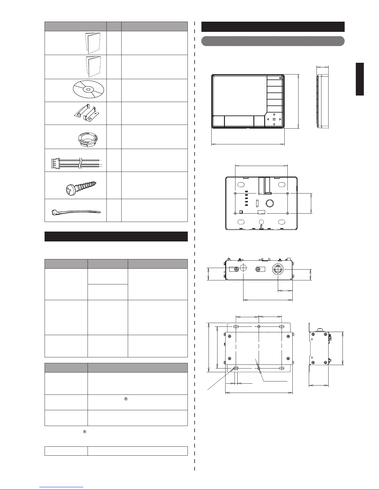
MAIN UNIT AND ACCESSORIES2.
The following parts are supplied. Use them as required.
Name and Shape Q’ty Application
Central remote
controller 1
Main unit
Contents
1. SAFETY PRECAUTIONS……………………………………………… 1
2. MAIN UNIT AND ACCESSORIES …………………………………… 1
3. ELECTRICAL REQUIREMENT ……………………………………… 2
4. SELECTING AN INSTALLATION LOCATION ……………………… 2
4. 1. Dimensions …………………………………………………… 2
4. 2. Installation restrictions ……………………………………… 3
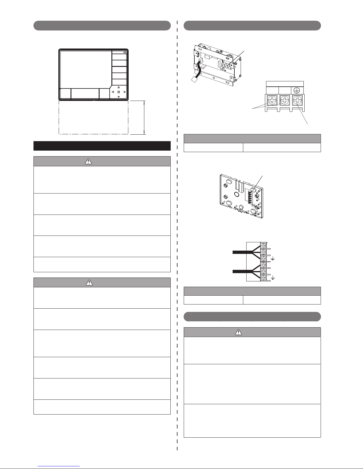
5. WIRING RULES ………………………………………………………… 3
5. 1. Terminal names ……………………………………………… 3
5. 2. Wiring rules …………………………………………………… 3
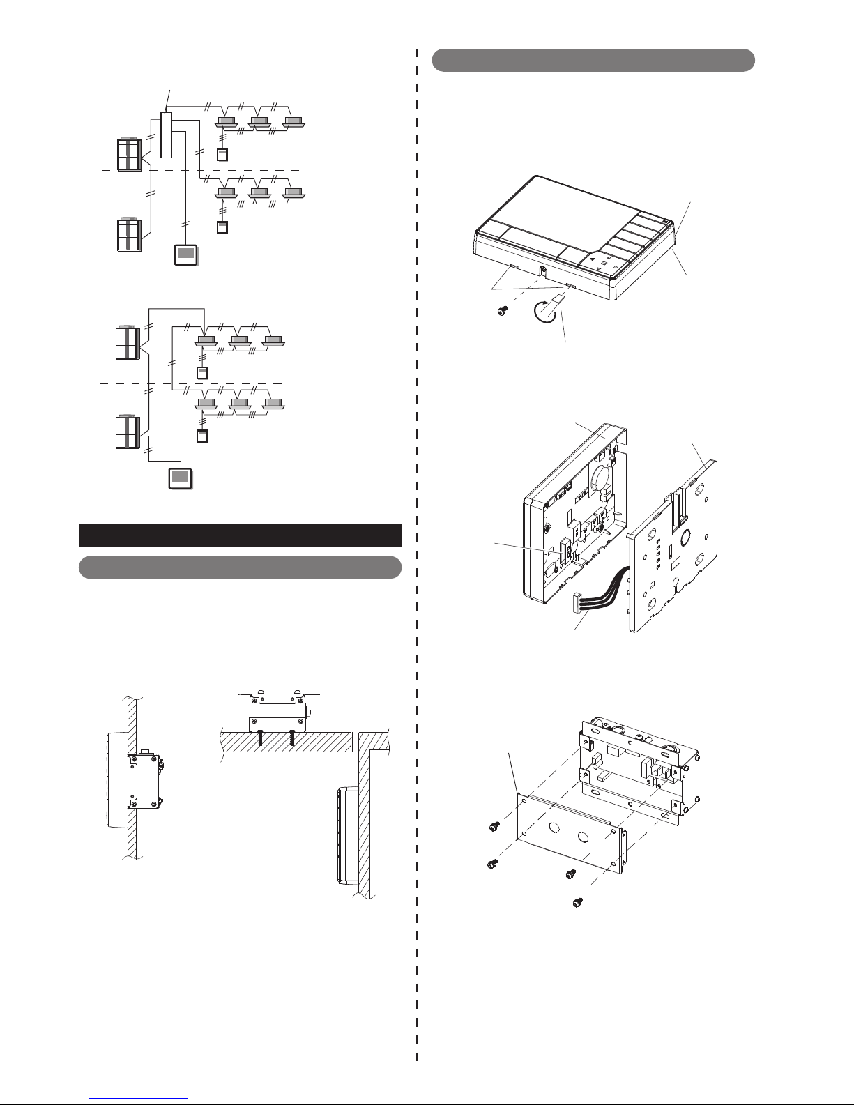
6. INSTALLATION METHOD …………………………………………… 5
6. 1. Selecting the Method of Installation………………………… 5
6. 2. Preparing Installation ………………………………………… 5
6. 3. DIP Switch Setting …………………………………………… 6
6. 4. Installation Method - Integrated type ……………………… 6
6. 5. Installation Method - Separate type………………………… 7
6. 6. External Input/Output function ……………………………… 9
7. TURNING ON THE POWER ……………………………………… 10

En-2
Name and Shape Q’ty Application
Installation
manual 1
This manual
Operating
manual 1
Instruction book for
operation
CD-ROM
1
Include the operating
manual for Central
remote controller
Holder 1
(Set)
For power supply unit
installation (Used for
separate type)
One touch bush
2
For protection of power
supply unit cable
Connection cable
1
For power supply unit
connection
Screw (M4 x 20 mm)
8
For Central remote
controller installation
Binder
4
Prevents dropping off
of the cable
ELECTRICAL REQUIREMENT3.
When connecting the Central remote controller, use the
following wiring.
Use Size Wire type
Power supply
cable
Max.1.25 mm2
(16AWG) Type60245 IEC57
or equivalent
Min.0.5 mm2
(20AWG)
Transmission
cable
0.33mm2
(22AWG)
22AWG LEVEL 4
(NEMA) non-polar 2
core, twisted pair solid
core diameter 0.65mm
(1/32 in.)
External input/
output cable
0.33mm2
(22AWG)
2 core, twisted pair
(Max.cable length :
25m (82ft.)
Use Remark
Power supply
cable
1Φ 50/60Hz 100-240V
2 wire + earth (ground)
(Always earth (ground) the unit)
Transmission
cable
L
ON
W
ORKS
compatible cable
External input/
output cable
Use cable in accordance with local
rules for cable
L
ON
W
ORKS
* is registered trademark of Echelon Corporation
in the United States and other countries.
Fuse capacity 5 A
SELECTING AN INSTALLATION LOCATION
4.
Dimensions4. 1.
Control unit(1) Unit: mm (in.)
162(6-3/8)
120(4-23/32)
Front view
Side view
25.7(1)
Rear view
118(4-21/32)
(1-3/4)
44.8
Power supply unit(2) Unit: mm (in.)
46
(1-13/16) (1-13/16)
46
25(31/32)
22
29 (1-5/32)
99 (3-29/32)
99 (3-29/32)
84 (3-5/16)
135 (5-5/16)
2-φ5
(3/32)
(3/16) (3/16)
5
(1-17/32)
(7/8)
67 (2-5/8)
R2.5
39.2

En-3
Installation restrictions4. 2.
Make a service space to perform installation work.
Unit: mm (in.)
150
(5-15/16)
Service space
WIRING RULES5.
WARNING
Always use the accessories and specied installation
work parts. Check the state of the installation parts.
Not using the specied parts will cause fall, water leak-
age, electric shock, re, etc.
Install at a place that can withstand the weight of the
unit and install positively so that the unit will not topple
or fall.
When installing this unit, make sure that there are no
children nearby. Otherwise, injury or electric shock
could result.
After this unit is installed, perform a test run to verify
that the device operates normally. Then describe the
operation method of this unit to the customer.
Install a circuit breaker. Not installing a circuit breaker
will cause electric shock or re.
CAUTION
Before opening the case of this unit, remove all the
static electricity accumulated on the human body. It
will cause an accident.
When the front cover xing screws are removed, be
careful that the front cover does not fall off. It will
cause an injury.
The circuit boards of this unit are at both the front
cover and rear cover. When a cover is opened, the cir-
cuit boards may be damaged by the screwdriver. This
will cause an accident.
The front cover and rear cover are connected by wir-
ing. When disassembling, be sure that the wiring is not
stretched.
Do not touch this unit's circuit board and circuit board
parts directly with your hands. Doing so may cause
electric shock or injury.
Tightening the mounting screws too tight will damage
the case of this unit.
Terminal names5. 1.
Power supply unit(1)
L N
Power supply
relay connector
output : DC 5V
Power supply terminal
Power supply
Power supply terminal
Earth (Ground)
L,N : Power supply
1Ø AC 100-240V
Tightening torque
Screw size M4 1.2 to 1.8 N·m (10.6 to 15.9 lbf·in)
Control unit(2)
DC +5V
GND
X1
X2
Rear panel terminal
(Rear panel side)
DC +5V
GND
X1
X2
Power supply cable-B (Red)
(Black)
(Green)
Transmission cable
Power supply terminal
Tightening torque
Screw size M2.6 0.3 to 0.5 N·m (2.7 to 4.4 lbf·in)
Wiring rules5. 2.
WARNING
Before starting installation work, turn off the power of
this unit and the connection destination. Do not turn on
the power again until installation is completed. Other-
wise, it will cause electric shock or re.
Use the accessories or specied power supply cable
and connection cables. Do not modify power supply
cable and connection cables other than those speci-
ed, do not use extension cables, and do not use
independent branch wiring. The allowable current will
be exceeded and cause electric shock or re.
Install the connection cables securely to the terminal
block. Conrm that external force is not applied to the
cable. Use connection cables made of the specied
cable. If intermediate connection or insertion xing are
imperfect, it will cause trouble, electric shock, re, etc.

En-4
WARNING
When connecting the power supply cable and trans-
mission cable, layout the wiring so that the cover of
this unit is securely xed. If the cover is imperfectly
xed, it may cause re or overheating of the terminals.
Perform earth (ground) work positively. Do not connect
the earth (ground) cable to a telephone earth (ground)
cable, water pipe, or conductor rod. It will cause
trouble or re.
Always fasten the outside covering of the cable with
binder. If the insulator is chafed by friction, electric
leakage may occur.
If any cable is damaged, do not repair or modify it
yourself. Improper work will cause electric shock or
re.
CAUTION
Do not bind up the power supply cable together with
the transmission cable or remote controller cable. It
will cause erroneous operation.
When performing wiring work, be careful not to dam-
age the cable or injure yourself. Also, connect the con-
nectors securely. Loose connectors will cause trouble,
heating, re, or electric shock.
Install the indoor and outdoor units, power supply
cable, transmission cable and remote controller cable
1m (40 in.) away from television and radio to avoid
distorted images and noise. Otherwise, a malfunction
could result.
Perform wiring so that water does not enter this unit
along the external wiring. Always install a trap to the
wiring or take other countermeasures. Otherwise it will
cause trouble, electric shock, or re.
Conrm the name of each unit and name of each
terminal block of the unit and connect the wiring in
accordance with the directions given in the manual so
that there is no incorrect wiring. Incorrect wiring will
damage the electric parts and cause smoke and re.
When installing the connection cables near a source
of electromagnetic waves, use shielded cable.
Otherwise,a breakdown or malfunction could result.
When wiring between the outdoor unit, indoor unit, and▪
Central remote controller, refer to the indoor unit and
outdoor unit installation manuals.
Always connect both ends of the earth (ground) con-▪
nection of the transmission cable.
Install the disconnect switch to the easily accessible▪
location.
Install the fuse (5A) to the L line of power supply cable.▪
L N
X1 X2
Y1Y2 Y3 L N
X1 X2
Y1Y2 Y3 L N
X1 X2
Y1Y2 Y3
L N
X1 X2
Y1Y2 Y3 L N
X1 X2
Y1Y2 Y3 L N
X1 X2
Y1Y2 Y3
L N
X1 X2
L N
X1 X2
X1 X2 Z1 Z2 H1 H2
Outdoor unit
(Master)
Power
supply
Power
supply
Power
supply
Power
supply
Power
supply
Power
supply
Power
supply
Central remote
controller
Indoor unit
Transmission
Power
Supply
Transmission
Wired remote
controller
Wired remote
controller
Central remote
controller
Fuse (5A)
Switch
(Disconnect switch)
2 remote
controllers
Wireless
remote
controller
Fuse (5A)
Switch
(Disconnect
switch)
Indoor unit
Indoor unit
Indoor unit
Indoor unitIndoor unit
2 remote
controllers
Tra ns -
mission
Tra ns -
mission
Tra ns -
mission
Tra ns -
mission
Tra ns -
mission
Tra ns -
mission
Tra ns -
mission
Tra ns -
mission
Remote
controller
Remote
controller
Remote
controller
Remote
controller
Remote
controller
Remote
controller
Power
Supply
Power
Supply
Power
Supply
Power
Supply
Power
Supply
Power
Supply
Power
Supply
1Ø 50/60Hz
100-240V
1Ø 50/60Hz
100-240V
Wire the transmission cable to any one of the following:▪
Transmission terminal block inside the indoor unit
(Fig. 1)
Terminal block for branch Transmission cable (Pro-
cured at the site) (Fig. 2)
Transmission terminal block inside the outdoor unit
(Fig. 3)
1Fig.
Central remote
controller
Refrigerant
system 1
Refrigerant
system 2

En-5
2Fig.
Separation when
terminal block used
Central remote
controller
Refrigerant
system 1
Refrigerant
system 2
3Fig.
Central remote
controller
Refrigerant
system 1
Refrigerant
system 2
INSTALLATION METHOD6.
Selecting the Method of Installation6. 1.
The following are the 2 methods for installing the central
remote controller based upon the installation method of
the control unit and power supply unit.
A. Control unit and power supply unit together (Fig. A)
B. Control unit and power supply unit separately (Fig. B )
AFig. BFig.
Preparing Installation6. 2.
Controller unit6. 2. 1
Remove the screw (1 pc).(1)
Remove the claws (2 places) with a at-blade (2)
screwdriver, and separate the front panel and
rear panel.
Front panel
Rear panel
Screwdriver
Claws
Disconnect the connection cable connector(3)
from the connector (CN13) of the front panel PC
board.
Rear panel
Front panel
CN13
Connection cable
Power supply unit6. 2. 2
Remove the screws (4pcs).(1)
Remove the cover.(2)
cover

En-6
DIP Switch Setting6. 3.
CAUTION
Use an insulated screwdriver to set the DIP switches.
Do not touch the DIP switch with your hands.
Before using this product, always set DIP switch (SW1)-▪
No.1 to “ON”.
If not set, when the main power is turned on again, the
set data by menu operation will be erased and cause
erroneous operation.
Do not change the setting of other switches.▪
[DIP Switch(SW1)]
Performs the enabling/disabling of the backup function▪
by the internal battery.
It is disabled when shipped from the factory to prevent▪
consumption of the charge.
123
ON
OFF
DIP Switch (SW1)
No. DIP Switch Details
OFF ON
1Disabled Enabled For enabling/disabling the
backup function.
2- Not used. Fixed to "OFF".
3- Not used. Fixed to "OFF".
(:Factory setting)
Installation Method - Integrated type6. 4.
Integrated type6. 4. 1
Pass power supply cable-A through Hole-A,(1)
and connect it to the power supply terminal of
the power supply unit PC board.
Fix with the binder.(2)
L N
Power supply cable-A
Hole-A
POWER SUPPLY
Binder (accessory)
Power supply terminal
Open the knockouts (2 places), and install the(3)
one touch bush (2 pcs, accessories).
Connect the connector of power supply cable-B(4)
(accessory) to the relay connector of the cable
coming from the power supply unit PC board.
One touch bush (accessories)
One touch bush
(accessories)
power supply
cable -B
(accessory)
Relay connector
knockout
knockout
Hole-B
Hole-A
Hole-C
Pass power supply cable-B through Hole-C and(5)
Hole-D, and connect it to rear panel terminal.
Pass transmission cable through Hole-B,(6)
Hole-C, and Hole-D, and connect it to rear
panel terminal. Fix with the binder(accessory).
Hole-B
Binder
(accessory)
Hole-A
Hole-C
Hole-D
Power supply
cable-B
Transmission cable
Fix with the binder (accessory).(7)
+5V
GND
X1
X2
Power supply cable-B
Rear panel terminal
Take care so that the earth (ground) cable does
not get into touch with other cables and parts.
Transmission cable
Binder
(accessory)

En-7
Install the power supply unit to a wall. Then in-(8)
stall the power supply unit cover and rear panel.
Be careful not to pinch the cable.
Screw ×6
(Accessories)
Screw ×4
Connect the connection cable connector to the(9)
connector (CN13) of the front panel PC board.
Install the front panel to the rear panel.(10)
CN13
When installing the front panel to the rear panel, install it care-*
fully so that the cable is not pinched or the parts of the circuit
board are not pushed by things projecting from the rear panel.
The circuit board parts may be damaged.
Install the screw (1 pc) and x the panels.(11)
Installation Method - Separate type6. 5.
For the cable, use the service parts to connect the power
supply unit and control unit.
Service parts
Name and Shape Q’ty Application
Extension cable (5m)
19708798011
A. Power supply unit wiring
Pass power supply cable-A through Hole-A,(1)
and connect it to the power supply terminal of
the power supply unit PC board.
Fix with binder rmly.(2)
POWER SUPPLY
L N
L N
Hole-A
POWER SUPPLY
Binder (accessory)
Power supply
cable-A
Open the knockout of hole-B section, and install(3)
the one touch bush.
Pass the extension cable (Service parts)(4)
through Hold-B, and connect it to the relay con-
nector coming from the power supply unit.
Fix with binder rmly.(5)
POWER SUPPLY
L N
One touch bush
(accessory)
Relay connector
Extension cable
(service parts)
Binder (accessory)
Hole-B
Hole-B
Hole-B
Install the power supply unit cover, and tighten(6)
the screws (4 pcs).

En-8
Fix the holder 1 assembly (2 places) with(7)
screws (2 pcs x 2 places).
Power unit cover
Screw×4
(When xing the
Holder, remove the 4
screws in advance.)
Screw×4
(Accessories)
Holder
(accessory)
B. Controller body wiring
Pull around the transmission cable as shown in(1)
the gure, and connect it to the terminal of the
rear panel.
Pull around the extension cable as shown in the(2)
gure, and connect it to the terminal of the rear
panel. And x with binder rmly.
Transmission cable
Extension cable
(service parts)
+5V
GND
X1
X2
Extension cable
Transmission cable
Terminal connection
Binder
(accessory)
Install the rear panel to a wall.(3)
Transmission cable
Screw ×4
(accessories)
Extension cable
Cut the thin part (gray marked part) at the top of(4)
the front panel with a cutter.
When passing the cable through the rear hole, do not cut off
Ì
the thin part at the top.
Cutting out
Connect the connection cable connector to the(5)
connector (CN13) of the front panel PC board.
Install the front panel to the rear panel.(6)
CN13
When installing the front panel to the rear panel, install it care-*
fully so that the cable is not pinched or the parts of the circuit
board are not pushed by things projecting from the rear panel.
The circuit board parts may be damaged.

En-9
Install the screw (1 pc) and x the panels(7)
External Input/Output function6. 6.
For connection cables, use the specied optional parts.
External input function6. 6. 1
This function performs “Emergency stop” or “Batch
start/stop(All On/All Off)” by using the signal to be input
externally at external input terminals.
There are 2 kinds of input method of External input
terminal: "Dry contact" or "Apply voltage contact".
Dry contact6. 6. 2
When a power supply is unnecessary at the input
device you want to connect, connect the connection
cables to CN6 and CN7.
*1
PCB
CN7
(Green)
CN6
(White)
Do not use the connectors other than specied connectors.*
Short circuit detection resistance (R ON) : ≤ 500 (ohm). *1.
Open circuit detection resistance (R OFF) : ≥ 100 (kilo-
ohm).
A twisted pair cable (0.33mm* 2(22AWG)) should be used.
Maximum length of cable is 25 m (82ft.).
Input Method Terminal Input signal Operation
Edge CN6
Low→High "Emergency stop" or
"All On"
High→Low "Emergency stop"reset
or "All Off"
Pulse
CN6 Low→High "Emergency stop" or
"All On"
CN7 Low→High "Emergency stop"reset
or "All Off"
For “Operation” and “Input method” switching, perform
the settings by “External Input Setting” of menu opera-
tion.
For details of setting method, refer to the operating
manual.
“Operation” “Emergency Stop”
“All On/All Off” (Bach start/stop)
“Input Method” “Edge”
“Pulse”
Apply voltage contact6. 6. 3
When a power supply must be provided at the input
device, connect the connection cables to CN11 and
CN12.
PCB
*4
*3
*2
*4
DC power
supply 24V
CN11 (White) CN12 (Green)
Do not use the connectors other than specied connectors.*
Make the power supply 24V. Select a power supply ca-*2.
pacity with an ample surplus for the connected load.
Do not impress a voltage exceeding 24V across pin 1, 3.*3.
The allowable current is DC5mA or less. (Recommended*4.
DC5mA)
Provide a load resistance such that the current becomes
DC5mA or less.
A twisted pair cable (0.33mm2(22AWG)) should be used.
Maximum length of cable is 25 m (82ft.).
Input Method Terminal Input signal Operation
Edge CN11
Low→High "Emergency stop" or
"All On"
High→Low "Emergency stop"reset
or "All Off"
Pulse
CN11 Low→High "Emergency stop" or
"All On"
CN12 Low→High "Emergency stop"reset
or "All Off"
For “Operation” and “Input method” switching, perform
the settings by “External Input Setting” of menu opera-
tion.
For details of setting method, refer to the operating
manual.
“Operation” “Emergency Stop”
“All On/All Off” (Bach start/stop)
“Input Method” “Edge”
“Pulse”
External output function6. 6. 4
CN9
PCB
1
3
4
+
+
++
-
-
-
-
*3) 2
DC power
supply 12V
connected unit
Connect-
ed load *2
Connect-
ed load *2

En-10
Provide a DC12V power supply. Select a power supply*1.
capacity with an ample surplus for the connected load.
Do not impress a voltage exceeding 12V across pins 1-2,
and 3-4
The allowable current is DC15mA or less. Provide a load*2.
resistance such that the current becomes DC15mA or less.
Polarity is [+] for pins 1,3 and [-] for pins 2,4.*3.
Terminal CH pin Condition
CN9
CH1
412V: 1 or more registered indoor units are
operating.
30V: All registered indoor units are
stopped.
CH2
2
12V: (1) An error occurs at 1 or more
registered indoor unit.
(2) An error occurs at remote control-
ler.
1
0V: (1) All registered indoor units are
operating normally.
(2) Remote controller is operating
normally.
Wiring method6. 6. 5
When using the external input/output function, the con-
nection cable is drawn out as shown in the gure below.
Fix the connection cable securely using the binder.
Ex. 1: When the cable is drawn out from the top of this
unit:
Cutting out
Connection cable
Binder
Ex .2: When the cable is drawn out from the back of this
unit:
TURNING ON THE POWER7.
CAUTION
Check that the power supply voltage is within the▪
specied range. If a power supply voltage outside the
specication is input, it will cause trouble.
Recheck the wiring. Incorrect wiring will cause▪
trouble.
After installation work is completed, check the following
contents:
Is Central remote controller power supply cable and
transmission cable wiring work complete?
Does the power supply match the rating of the Cen-
tral remote controller?
Turn on the power of Central remote controller. Since
there is no power switch at this controller main unit,
turn on the power by means of the power distribution
panel (breaker).
If the following installer setting screen is displayed
at the screen of the Central remote controller panel,
installation work is complete.
For setting and operating of the Central remote control-
ler, refer to the separate operating manual.
Since there is some kind of a problem when the installer set-*
ting screen does not appear, recheck the work contents.
Other manuals for UTY-DCGY
1
This manual suits for next models
1
Table of contents
Other AirStage Controllers manuals
Popular Controllers manuals by other brands

Sensor Access
Sensor Access IC2001 manual

GE
GE C70 instruction manual

Texas Instruments
Texas Instruments TPS70351EVM user guide

Chino
Chino JU Series instruction manual

Control Data
Control Data 3234 Series Hardware reference manual

Mitsubishi Electric
Mitsubishi Electric Melservo HF-KN Series instruction manual