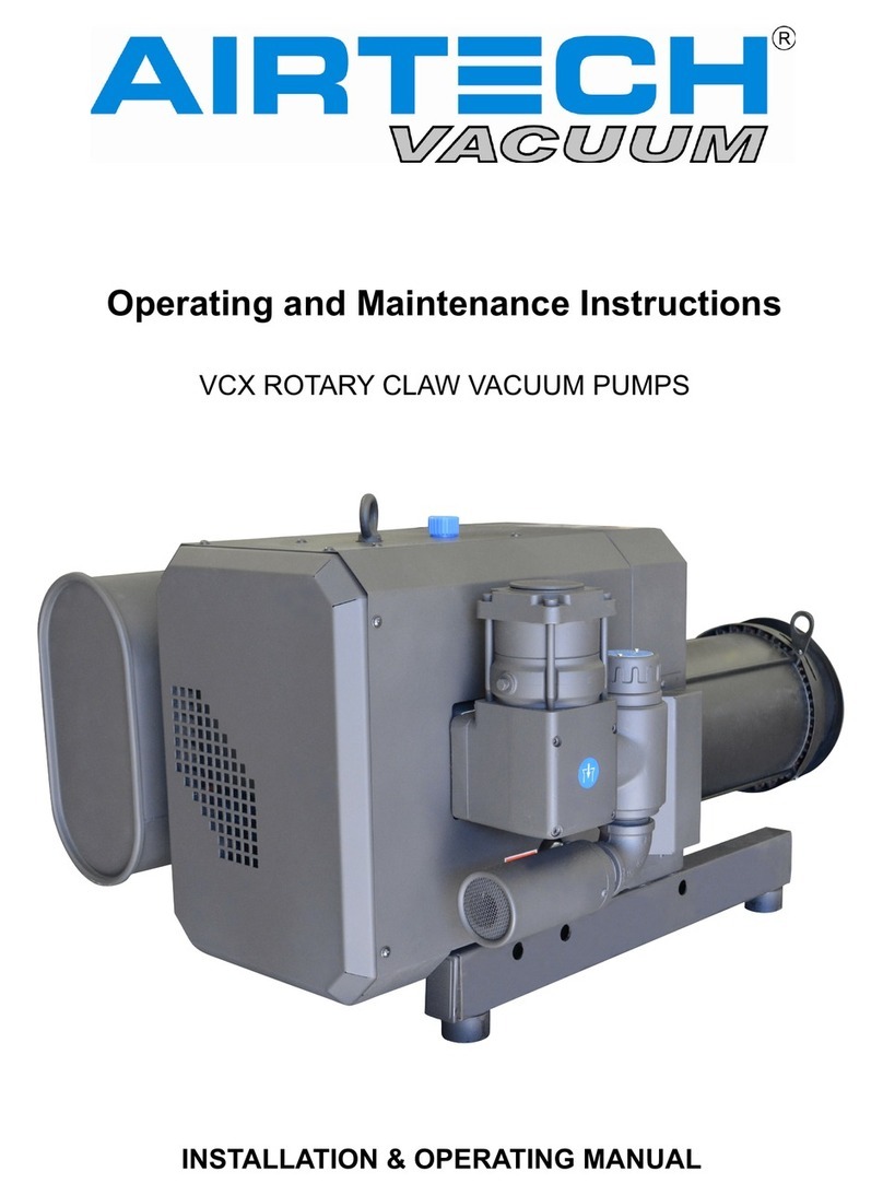
AirTech 3AV95 Setup guide

Repair Instructions
3AV 30 to 3AV 430

REPAIR MANUAL
3AV 30 - 3AV 430
Table of Contents
Section:
1.0 Dismantling Pump
1.1.1 3AV95/ 3AV130/ 3AV155/
3AV330/ 3AV430
1.1.2 3AV255
3
3
3
1.2 Disassembling Impeller 4
1.3 Disassembling Shaft Seal Housing 4
1.4 Disassembling Mechanical Seal 4
2.0 Reassembling Pump 5
2.1 Reassembling Mechanical Seal
2.1.1 Rotating part of Mechanical Seal
2.1.2 Standstill part of Mechanical Seal
5
5
5
2.2 Reassembling Shaft Seal Housing 6
2.3 Reassembling and Adjusting Impeller 7
2.4 Reassembling Inter Casing 7
2.5 Reassembling Pump Case and
Shaft Seal Housing 8
2.6 Reassembling Pump Case and
Inter Casing 8
2
Page
Number:

General Remarks
Before disassembly the pump, isolate the electrical input and disconnect the operation liquid connec-
tion, and inlet and outlet connections. Disassemble and reassemble the pump on a level surface. Mark
all parts as they become accessible during disassembly to ensure correct positioning for reassembly.
Before starting disassembly, collect the parts, materials and standard tools, which are required for
disassembly and reassembly of the pump.
Special Tools, Parts and Materials
Feeler gauge
Molykote G-n Paste or equivalent
Liquid sealant e.g. Epple 32
Metal straight edge
Loctite 242 and Primer
Solvent such as kerosene
1Dismantling Pump
•Remove five fixed pump casing screws (901)
•Remove pump casing (101)
•Remove inter casing (137)
1.1 Disassembling Inter Casing from Pump Casing
1.1.1 Type 3AV 95/3AV 130/3AV 155/3AV 330/3AV 430
•Remove fixed hexagon socket countersunk head screw (901.2) at inter casing (137)
•Remove inter casing (137) from pump casing (101)
1.1.2 Type 3AV 255
•Remove fixed screwed plug (903) at pump casing (101)
•Remove fixed hexagon socket head cap screw (914) at pump casing (101)
•Turn around pump casing (101) and inter casing (137)
•Remove inter casing (137)
Repair Instructions 3AV 30 - 430
3

1.2 Disassembling Impeller
•Block the impeller (230) at shaft seal housing (441)
•Remove fixed hexagon nut from impeller adjusting screw
•Remove impeller (230) from shaft
•Remove impeller screw (906) and distance springs (950) from shaft. Notice position of distance
springs
1.3 Disassembling Shaft Seal Housing
•Remove fixed hexagon nut or hexagon head cap screw at motor flange
•Remove shaft seal housing from motor flange
1.4 Disassembling Mechanical Seal
•Turn around shaft seal housing
•Press mechanical seal out of seat at shaft seal housing (back side)
•Remove rotating part of mechanical seal at impeller
Repair Instructions 3AV 30 - 430
4

2Reassembling Pump
(e.g. 3AV 55)
CAUTION
Thoroughly clean all parts before reassembly, be sure to remove all old gasket mate-
rial from mounting flanges. Remove burrs from mating surfaces and mounting faces.
Remove rust at seat for mchanical seal.
2.1 Reassembling Mechanical Seal
2.1.1 Rotating part of Mechanical Seal
Coat the O-ring of mechanical seal with thin-bodied oil
Move mechanical seal (047) over the shaft of impeller (230). Don‘t touch the surface of the mechanical
seal. Coat the bore of impeller with molykote
2.1.2 Standstill part of Mechanical Seal
Coat the O-ring of mechanical seal with thin-bodied oil
Install mechanical seal (047) at shaft seal housing (441). Don‘t touch the surface of the mechanical
seal
Repair Instructions 3AV 30 - 430
5

Repair Instructions 3AV 30 - 430
2.2
Reassembling Shaft Seal Housing
Set motor on air ventilation cap
Install distance springs (950, with molykote coated) on the impeller adjusting screw (906). Be carefull
because the distance springs should be mounted as shown in the picture above. Coat the thread of
impeller adjusting screw also with molykote
Tread in the impeller adjusting screw into the motor shaft
Align the studs of the motor flange with the holes of the shaft seal housing (441)
Install four washers on the studs of the motor flange
Thread on four nuts on the studs of the motor flange and tighten nuts.
6

Repair Instructions 3AV 30 - 430
2.3
Reassembling and Adjusting Impeller
Install impeller on motor shaft
Coat the disk of impeller with liquid seal (Epple)
Install washer on the coated disk of impeller
Thread on nut to impeller adjusting screw
Adjust impeller with the impeller adjusting screw. There should be a gap of 0.1 – 0.15 mm between the
surface of the impeller and the surface of the shaft seal housing. Use the metal straightedge and the
feeler gauge to adjust the gap.
Block the impeller if the gap is correct. Tighten nut of the impeller screw.
Turn impeller. There should be no contact between impeller and shaft seal housing and also no con-
tact between impeller and metal straightedge. If there is any contact re-adjust the impeller.
2.4
Reassembling Inter Casing
Coat shaft seal housing (411) with liquid seal (Epple)
Install inter casing on shaft seal housing. Correct position of inter casing is given through the pins at
shaft seal housing
7

Repair Instructions 3AV 30 - 430
2.5
Reassembling Pump Case and Shaft Seal Housing
Coat pump casing (101) with liquid seal (Epple)
Install pump case (101) on inter casing (137). Thread in five hexagon head screws (901). Tighten the
screws (901) cross-wise.
Thread in all disassembled hexagon socket screwed plugs with their gaskets.
2.6
Reassembling Pump Case and Inter Casing
Install O-Ring (412) at pump casing
Install inter casing at pump casing. Correct position is given through the pin of pump case
Apply Loctite to thread and thread in hexagon socket countersunk head screw (901.2) and tighten
screw (screw 914 at 3AV 255 / screw 904 at 3AV 330-430).
2.7
Reassembling Pump Case and Shaft Seal Housing
Type 3AV 95-430
Install O-ring (412) at shaft seal housing
Install pump case (101) on shaft seal housing (441)
Thread in five hexagon head screws (901)
Tighten the screws (901) cross-wise
Type 3AV 95/3AV 130/3AV 155/3AV 330/3AV 430
8

Repair Instructions 3AV 30 - 430
3)
2)
412
561.1
746
598
901.3
550.1
901
047 Gleitringdichtung mechanical seal
101 Pumpengeh use pump casing
137 Steuerscheibe inter casing
230 Laufrad impeller
411 Dichtring joint ring
411.1 Dichtring joint ring
412 O-Ring o-ring
441 Geh use f¤r Wellendichtung shaft seal housing
524 Wellenschutzh¤lse shaft protection sleeve
550 Scheibe disk
550.1 Scheibe disk
550.2 Scheibe disk
550.3 Scheibe disk
561 Kerbstift grooved pin
561.1 Kerbstift grooved pin
598 Blech sheet
746 Klappe flap
800Motor m
otor
900 Schraubescrew
901 6ktSchraubehexagonhead capscrew
901.1 6ktSchraube hexagon head capscrew
901.26kt Schraube hexagonheadca
pscrew
901.36kt Schraube hexagonh
ead capscrew
903 Verschlussschraube screwedplug
903.1 Verschlussschraube screwedplug
903.2Ve
rschlussschraubes
crewed plug
906Laufradschraube impeller screw
9206kt Mutter hexagon nut
920.1 6ktMutterhexagonnut
940Passfederk
ey
950Feder spring
970 Schildshield
800
940
441
970
561
230
524
137
101
411
903
411.1
903.1
550.2
901.2
550
906
920
047
550.3
950 550.1
920.1
550.1
901.1
411.1
903.2
900
1)
2)
1) 35/55/65
2) 14/30/50/60
3)nur bei 3AV 155-14/50/55 for 3AV 155-14/50/55 only
9

301 Veterans Boulevard
Rutherford, NJ 07070
Tel: 1 888 222 9940
Fax: 201 569 1696
2nd Building,
Jiangbian Second Industrial Park
Songgang Town, Bao'an District
Shenzhen, China
Tel: +86 755 81730991(Ext.8018)
Fax: +86 755 81730986
www.airtechchina.com
SOUTH
2121 Newmarket Pkwy. Suite 110
Marietta, GA 30067
Tel: 770 690 0700
Fax: 770 690 0709
EUROPE
Pfaffenpfad 5
D-97440 Werneck
Germany
Tel: +49 9722 943 96 0
Fax: +49 9722 943 96 29
www.airtecheu.com
WEST
ASIA
CHINA
42 Digital Drive #9
Novato, CA 94949
Tel: 415 382 9000
Fax: 415 382 9700
www.airtechusa.com
Pfaffenpfad 5
D-97440 Werneck
Germany
Tel: +49 9722 943 96 0
Fax: +49 9722 943 96 29
www.airtechas.com
This manual suits for next models
5
Table of contents
Other AirTech Water Pump manuals