Airtecnics K7 Series User manual

INSTALLATION, OPERATION AND MAINTENANCE MANUAL
K7 purification and disinfection units
Please read the instructions carefully before installation.
Give this manual to the end user.
SECURITY ADVISE SYMBOLS
WELDOM10010-R1(03/03/21)
Attention, Danger, Safety Warning!
High voltage or electric current hazard!
Danger of injury!
¡Attention! Do not stand under the load:
Heavy weight.
Attention! Wear protective glasses
UV-A: Ultraviolet radiation.
Important information.

2
INDEX
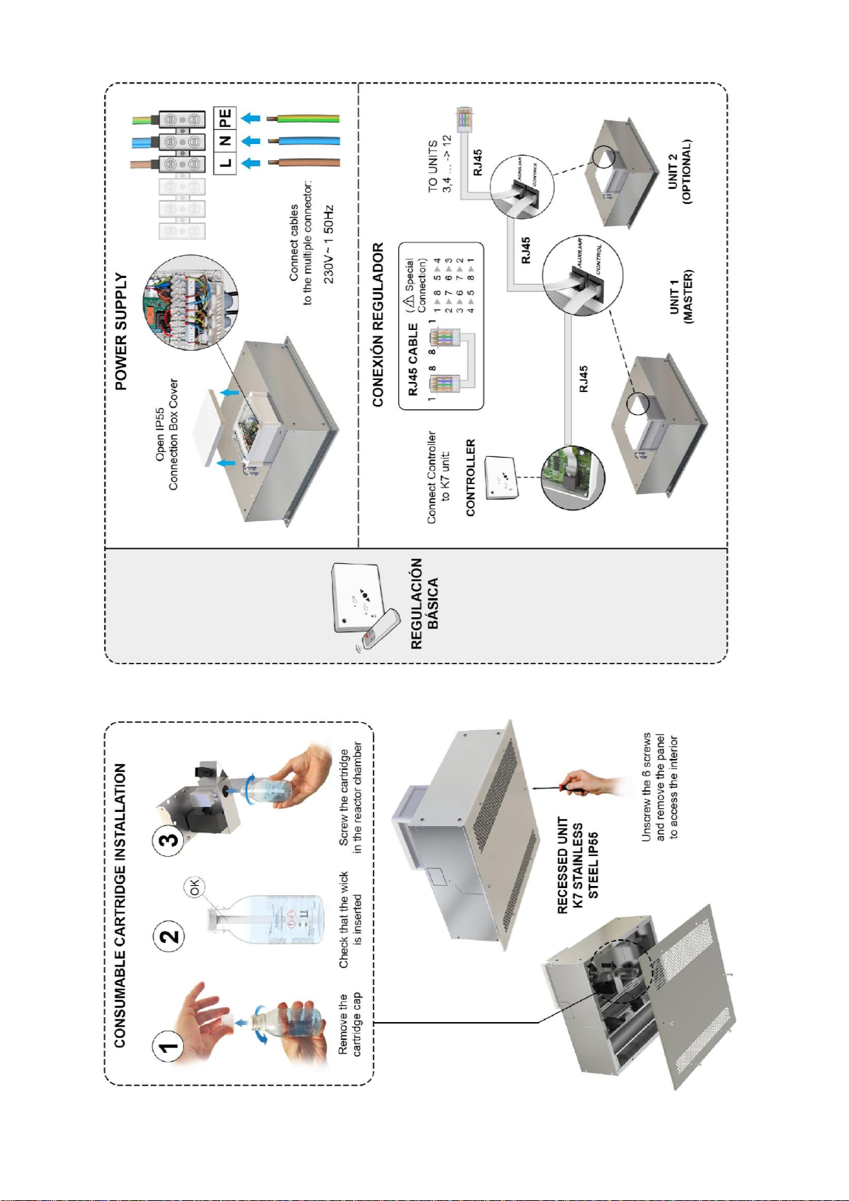
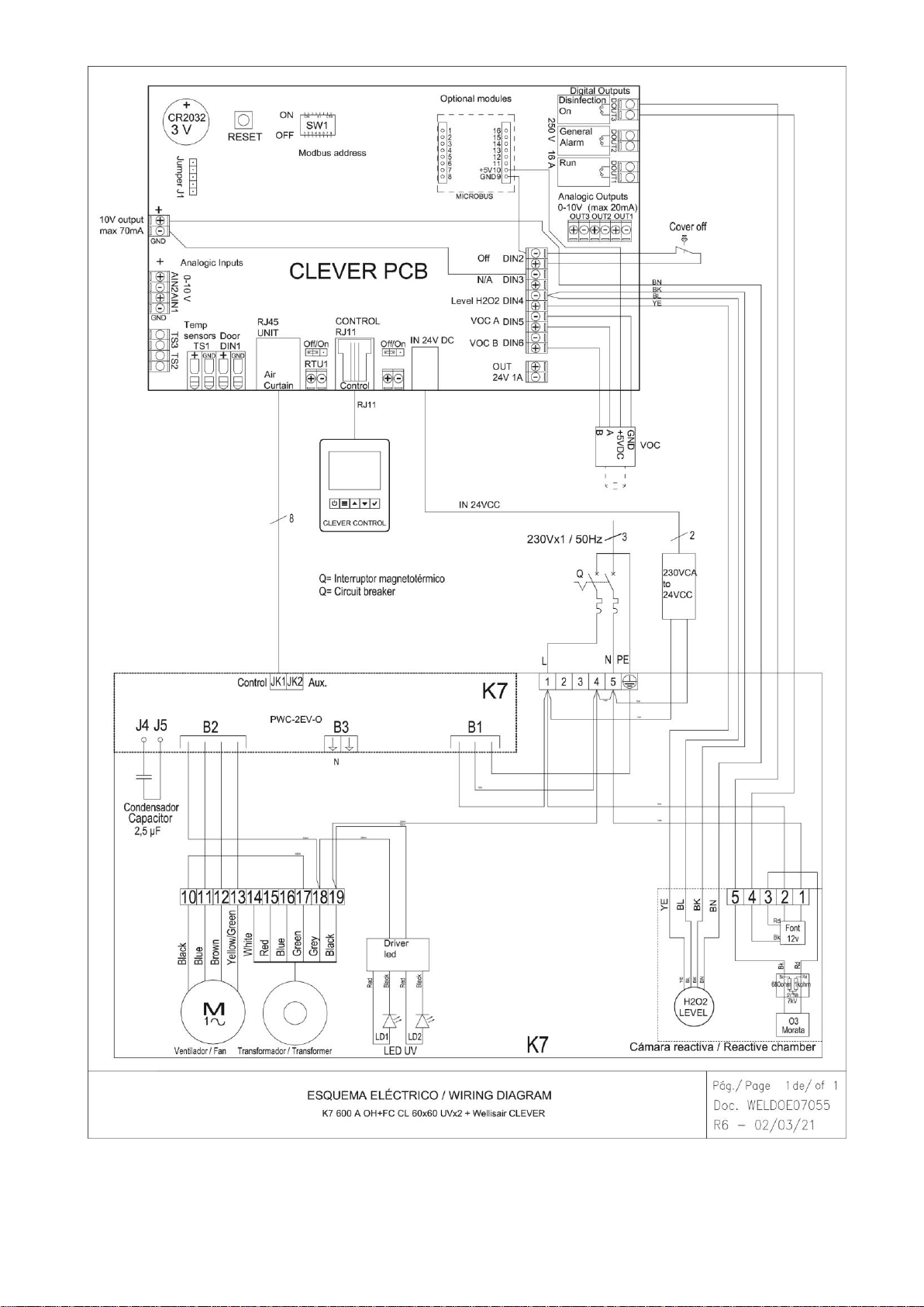
CONNECTION DIAGRAM....................................................................................................................................3
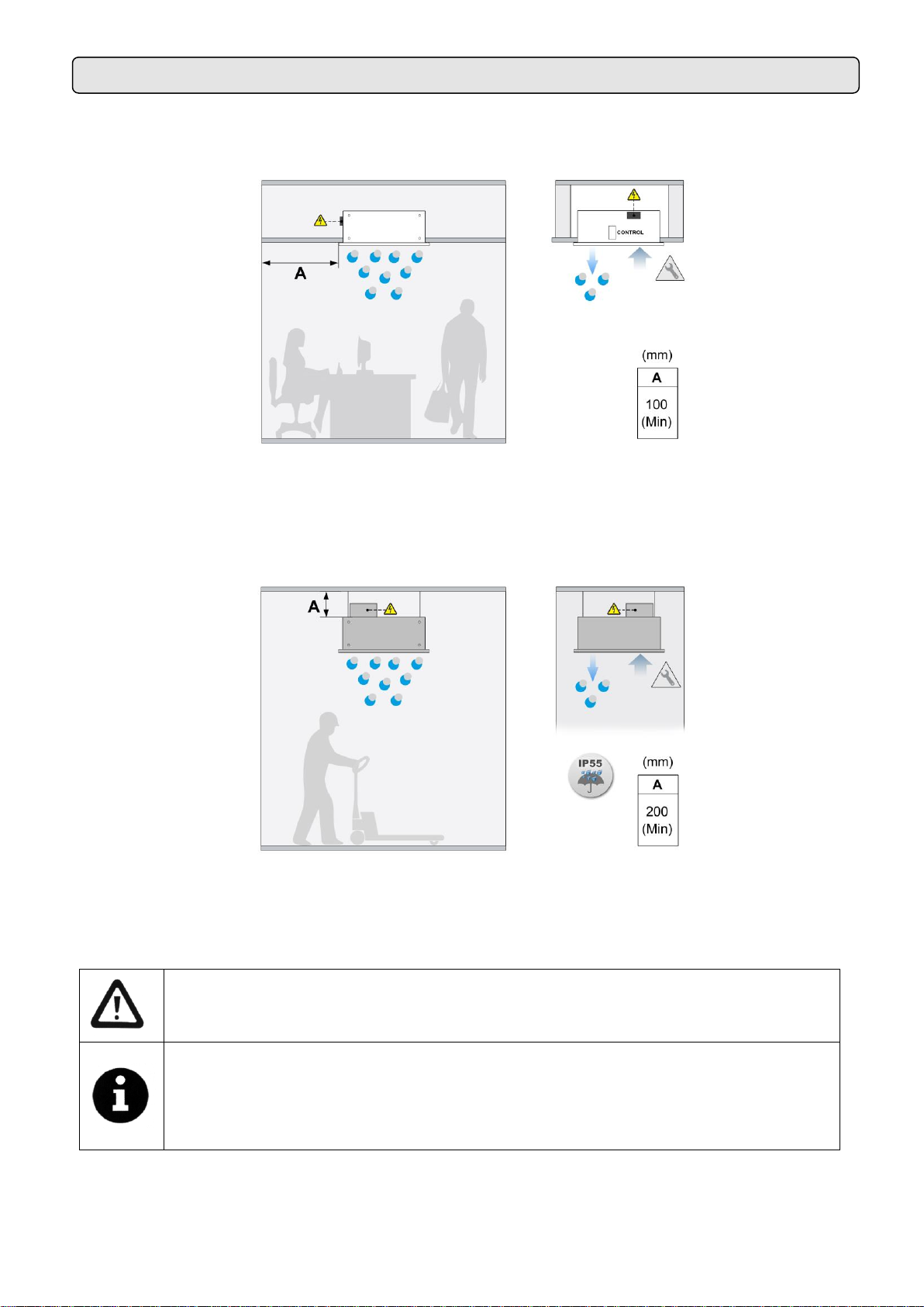
INSTALLATION ....................................................................................................................................................5
Power supply....................................................................................................................................................6
PCB and control ...............................................................................................................................................6
Fixings..............................................................................................................................................................6
TRANSPORT AND STORAGE ............................................................................................................................7
OPERATING INSTRUCTIONS ............................................................................................................................7
Control board features......................................................................................................................................7
Standard controller features.............................................................................................................................7
Special controls................................................................................................................................................8
Remote control features...................................................................................................................................8
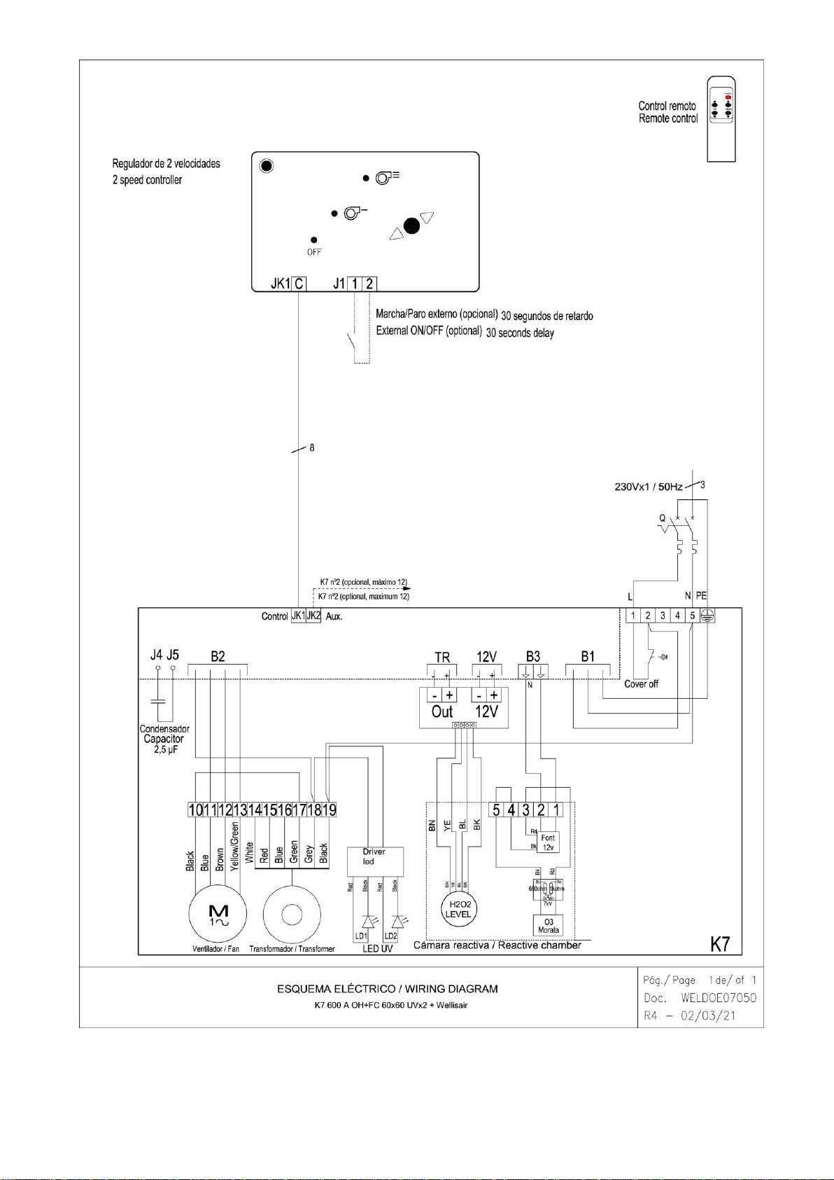
WIRING DIAGRAMS............................................................................................................................................8
DATASHEET ......................................................................................................................................................12
Exterior cleaning.............................................................................................................................................14
Internal cleaning.............................................................................................................................................14
REPAIRS AND REEMPLACEMENTS ...............................................................................................................15
Replacement of the consumable....................................................................................................................15
Standard purifier motor or turbine replacement .............................................................................................16
Fuse replacement...........................................................................................................................................17
PCB replacement ...........................................................................................................................................18
FAILURES AND SOLUTIONS............................................................................................................................19
ACCESSORIES..................................................................................................................................................20
DECLARATION OF CONFORMITY...................................................................................................................21
Purifier identification.......................................................................................................................................22
GUARANTEE .....................................................................................................................................................22

3
CONNECTION DIAGRAM

4

5
INSTALLATION
Valid for models: K7
•Recessed unit K7
MAX. Maximum recommended height, MIN. Recommended minimum distance
(**) Removable sides
•Recessed unit K7 Stainless Steel IP55
MAX. Maximum recommended height, MIN. Recommended minimum distance
(**) Removable sides
The minimum recommended distance between the intake grille and any obstacle is 200mm.
Assembly, connection and disconnection, electrical wiring and maintenance must be
carried out exclusively by qualified personnel, observing these instructions and in
accordance with the applicable standards. In case a special control is supplied, a
specific manual is attached that must be used for its operation and installation.
Depending on the model it is not necessary to remove the service grill to connect the
equipment. All the connections (power and control) and necessary fixings are external
(in the standard case, located on the top or side of the purifier), internal (in the case of
having Clever Control) or in the external waterproof box (in the case of having IP
protection). The equipment has a service grid to place the consumable cartridge and
carry out repairs (see repairs section).

6
Power supply
Depending on the model, you have to access different sites to make your connection:
K7 600 A OH+FC (with standard control) -> On one of the outer sides there is the power board, where the
power must be connected.
K7 600 A OH+FC CL (with advanced Clever control) -> On one of the outer sides there is a black box where
the power supply must be connected.
K7 600 A OH+FC SS (IP55 standard control) -> There is a waterproof box above the purifier where the power
must be entered and connected to the internal terminal block by means of a cable gland.
PCB and control
Depending on the model, you have to access different sites to make your connection. All models include an
RJ telephone cable to communicate with the control.
K7 600 A OH+FC (with standard control) -> using the 7-meter RJ45 cable, connect the power board (located
on one of the outer sides of the purifier) and the control. In this case, it is not necessary to open the intake
grille.
K7 600 A OH+FC CL (with advanced Clever control) -> using the 7-meter RJ11 cable, connect the Clever
regulation board (located inside the equipment) and the TFT control of the Clever. In this case, it is necessary
to open the intake grille (see section “repairs and replacements”). The RJ11 cable must be routed to the
outside through a hole in the top of the housing.
K7 600 A OH+FC SS (IP55 standard control) -> using the 7-meter RJ45 cable, connect the power board
(located in the waterproof box above the purifier) and the control (located inside an IP65 waterproof box). To
enter the cable in each box, you must use the cable glands supplied with the purifier.
The communication between the controller and the board is digital and low voltage.
There are optional accessories and controllers designed to meet the needs of each client (Clever, brackets,
etc.).
The new generation of total control is the Clever control. It leads the new generation of regulation with
maximum control that provides maximum energy efficiency. In addition, it allows you to visually monitor the air
quality and the status of the disinfection function. For more information request the Clever manual.
Fixings
The equipment has several external attachment points (see situation in the model characteristics section).
The anchor must be dimensioned according to the K7 weights indicated on the technical data page.
Installation can be done using threaded rods, turnbuckles or other supports. See available supports in the
accessories section.

7
TRANSPORT AND STORAGE
OPERATING INSTRUCTIONS
Attention! Heavy product.
Do not stand under the suspended equipment during transport or assembly.
Store in a dry place protected from the elements. If the packaging is open, cover the purifier to protect it from
dust. Do not step on or place heavy load son it to avoid damage to he material. Storage temperatura between
-20ºC and +40ºC.
When transporting the material, make sure that it is not damaged by the forklift (penetration of the fork in the
packaging). The instructions on the packaging must be observed.
Includes a consumable with disinfectant liquid (hydrogen peroxide solution).
(EN) PRECAUTIONS: Causes skin irritation.Causes serious eye irritation. It can irritate
the respiratory tract. Avoid breathing dust/fume/gas/mist/vapors/spray. Wash hands
and forearms thoroughly after handling. Use only outdoors or in a well-ventilated área.
Wear protective gloves/clothing/glasses/mask. IN CASE OF SKIN CONTACT: Wash
with plenty of soap and wáter. IN CASE OF INHALATION: Remove person to fresh air
and keep in a position that facilitates breathing. IN CASE OF CONTACT WITH EYES: Rinse carefully with
water for several minutes. Remove contact lenses when present and can be done easily. Continue with the
wash. In case of skin irritation: Consult a doctor. Immediately call a POSISON CENTER or doctor. Remove
contaminated clothing. Store in a well ventilated place. Keep the recipient hermetically sealed. Keep locked
up. Dispose of contents/container to an approved waste disposal facility.
Control board features
The relay boards adjust the two fan speeds depending on the condenser connection.
Standard controller features
•2 ventilation speeds.
•Memory: guarantees that, in the
evento o fan interruption in the power
supply, the speed that we had
selected is preserved when the
service is restored. This function can
be connected-disconnected using the
ON/OFF switch located inside the
controller.
•RJ45 cable and digital communication: they have a fast
connection with a telephone type cable and digital
communication between the controller and the purifier. This
type of communication is reliable even over long distances.
•External start-stop: inside the controller there is the possibility of connecting a normally open contact
(1,2) that governs the on-off of the equipment through any external device. The contact is potential
free. When the contact is open then the purifier is on. When the contact closes the purifier has a 30
second delay before stopping. It can be used for a timer, temperature sensor, fire alarm, PLC, etc.

8
•Remote control: all standards controls have an IR receiver that allows you to use a remote control.
•End of consumable: when the level sensor of the disinfectant cartridge sends the signal through the
board, the control flashes the zero-speed led (red led). In this way the user is notified that the cartridge
must be changed. The ventilation of the purifier continues its operation as it did before the
consumable was finished. Only hydroxyl radicals stop working.
Special controls
If there is a need to control more parameters, there is an advanced control, the Clever. It has its own manual
where all its functions are explained.
Remote control features
WIRING DIAGRAMS
The following diagrams are attached:
K7 600 A
•Purifier and disinfectant K7 600 A OH+FC with standard control. Diagram WELDOE07050
•Purifier and disinfectant K7 600 A OH+FC CL with advanced Clever control. Diagram
WELDOE07055
K7 600 A SS
•Purifier and disinfectant K7 600 A OH+FC with standard control. Diagram WELDOE07060
In case there is a need to connect the purifier to a PLC, the corresponding diagram will be sent.
In electrically heated air curtains, it is
used to modify the heating power. It is
not used for the air purifier.
It works with batteries
of the type AAA/LR03
Increase or decrease
the speed of the fans
Infrared system
Turning the air purifier on and off

9

10

11

12
DATASHEET

13

14
MAINTENANCE INSTRUCTIONS
For safety, before cleaning, turn off the appliance using the controller.
It is forbidden to open the service grille (risk of electric shock, trapping in fans and
glare from UV-A light).
Repairs must be carried out exclusively by authorized personnel.
The inside of the appliance must not be cleaned with water or steam.
Exterior cleaning
It is recommended to clean the intake grille weekly. In addition, it is important to make sure that the purifier is
turned off, on the contrary, the mixture between dust and a damp cloth would form a kind of paste that could
damage the fan rotor when it sucks in the air.
An annual cleaning of the discharge area should be performed.
Cleaning the body of the purifier should be done with a damp cloth and a conventional detergent. Do not use
caustic or acid-containing detergents.
The intake grille prevents objects from entering the internal elements. It is advisable to periodically check that
the intake grille is free of any object that could prevent the entry of air (papers, etc.).
Internal cleaning
In models with perforated grille, it is advisable to clean the inside of the unit with a vacuum cleaner at least
once every 2 years (*), better to do it before winter, using qualified personnel.
It is recommended to clean the inside of the equipment frequently with the help of a vacuum cleaner. (*)
(*) These periods are indicative depending on the conditions of each installation. In places with a high number
of suspended particles it is desirable to increase the frequency of interior cleaning.

15
REPAIRS AND REEMPLACEMENTS
The assembly and the electrical connection must be carried out exclusively by specialized
personnel and observing these instructions.
Before carrying out any repairs, you must:
•Notify staff and indicate that work is in progress.
•Disconnect the power and protect the termal magnet (so that no one can
accidentally actuate it).
•Make sure there is no voltage on the purifier.
•Make sure that the fans have stopped.
•Use only original spare parts.
To open the intake grille, follow these steps:
•Remove the screws from the intake grille.
•Gently pull the grill down.
Replacement of the consumable
Before changing the consumable, notify and indicate that is working, stop the purifier with the control and
make sure that the turbine has completely stopped.
Disassemble the intake grille as indicated in the previous step and proceed to unscrew the bottle from the
reactor chamber.
Disassemble the intake grille as indicated in the previous step and proceed to unscrew the bottle from the
reactor chamber.
Open the new consumable and insert the wick into the bottle. Then screw the bottle into the reactor chamber
and close the suction grille again.

16
There is a safety switch, which deactivates the equipment when opening the grille. This way, the UV-A LED
light can never be seen on while maintenance is being performed.
Standard purifier motor or turbine replacement
Before changing the motor, warn and indicate that is working, disconnect the power supply, make sure that
there is no voltage and that the turbine has stopped.
Remove the side from the motor side.
Disconnect the motor connector on the
power board (*)
Then loosen the turbine fixing screw (Allen 2.5mm) through the discharge port.

17
Remove the motor by loosening the fixing screws. Assemble the replacement one following the process in
reverse order, making sure that the motor and turbine fit perfectly, the turbine screw must coincide with the flat
part of the motor shaft.
Remove with a screwdriver the side of the motor side.
(*) In case of the K7 600 A OH+FC SS, the motor connection must be disconnected in the IP55 waterproof box
located above the purifier.
Fuse replacement
Before doing any manipulations, warn and indicate that you are working, disconnect the power supply, make
sure that there is no voltage and that the fans have stopped.
For K7 600 A OH+FC and K7 600 A OH+FC CL, open the intake grille and remove the fuse by hand or the
help of a screwdriver and replace it.
In the case of the K7 600 A OH+FC SS, the board is inside the waterproof box above the purifier. Simply
unscrew the cap and remove the fuse by hand or the help of a screwdriver and replace it.

18
PCB replacement
K7 600 A OH+FC (standard control) -> Open the inspection door and disconnect the cables from the board
that are visible and the capacitor. Unscrew the board located on one of the sides, disconnect the power supply
and pull it:
K7 600 A OH+FC CL (advanced Clever control) -> Open the inspection door and disconnect the cables from
the board that are visible and the capacitor. Unscrew the power board from the top and perform the necessary
repair:
K7 600 A OH+FC SS (standard control IP55) -> Open the waterproof box above the purifier and disconnect all
cables from the board. Unscrew the bracket clamp to the waterproof box and finally unscrew the bracket plate.

19
FAILURES AND SOLUTIONS
More than 95% of the complaints are submitted during the start of operation of the equipment and are due
to installation errors. Reviewing the following 3 points, more than 90% of the incidents are solved:
A) RJ45 cable manipulated: The cable that connects the controller to the air purifier is an 8 lines crossed RJ45 cable. If
manipulated (cut or removed the connector) and incorrectly joined (reverse way) the purifier Will not work well. Moreover
it can damage the electronics. To solve the problem just turn the connector of the cable (see connection diagram in the first page).
B) Wrong connection of the RJ45 cable. Verify whether the connector position is the correct, between the “control”and “auxiliary”,
according to the installation diagram (particularly if there are several purifiers with a single controller).
C) Wrong current supply/input.The purifier input depends on the type of current available and also on the heating type of the unit.
Connect the unit according to the connection diagrams of the first page.
More common failures and solutions
Effect
Problems
Solutions
All lights of the
controller are OFF
Is the RJ45/RJ11 cable the original
(not manipulated), with no
enlargements either shortenings?
Change cable or reconnect it correctly.
Does the current reaches the
connection box?
Correctly connect the terminals of the connection box:
Between L and N there must be 230V.
Is the controller connected to the
purifier, to the connector “Control”
of the PCBoard?
Connect the cable from the controller to the “Control”, never to the “Aux”.
Is the fuse of the PCBoard in good
conditions?
Check the fuse and replace it in case it is necessary (type T, slow action)
Is the grille in place?
Place the grille in the corresponding position and close the equipment
Some lights of the
controller are flashing
Zero speed light blinks
The consumable has run out and needs to be replaced
The speed changes
continuously
with no apparent
reason but the
lights of the
controller are not
flashing.
Probably the RJ45 cable is near
interference sources, transmitters,
cable plates, particularly those that
supply current to motors, etc.
Pass the cable the furthest possible away from interference sources,
particularly when long distances or use a screened table.

20
ACCESSORIES
Clever Control
External temperature sensor
Interface II
Intelligent proactive regulation,
advanced functions, Automatic/manual
working, door delay, timer, save
energy program, multi equipment
management, BMS Modbus
connection, etc.
It permits to take the
temperatura from a place
different to the control.
Allows the connection to a
centralized management system
(BMS, PLC, etc.).
Supports, vibration dampers, etc. depending on the model.
20m and 50m RJ45 cable
This manual suits for next models
3
Table of contents
Other Airtecnics Air Cleaner manuals