Airtecnics Kleenbox User manual

INSTALLATION, OPERATION AND MAINTENANCE MANUAL
Kleenbox, HEPA filtration box
Please read the instructions carefully before installation.
Give this manual to the end user.
SECURITY ADVISE SYMBOLS
WELDOM20110-R0(24/02/21)
Attention, Danger, Safety Warning!
High voltage or electric current hazard!
Danger of injury!
¡Attention! Do not stand under the load:
Heavy weight.
Attention! Wear protective glasses
UV-A: Ultraviolet radiation.
Important information.

2
INDEX
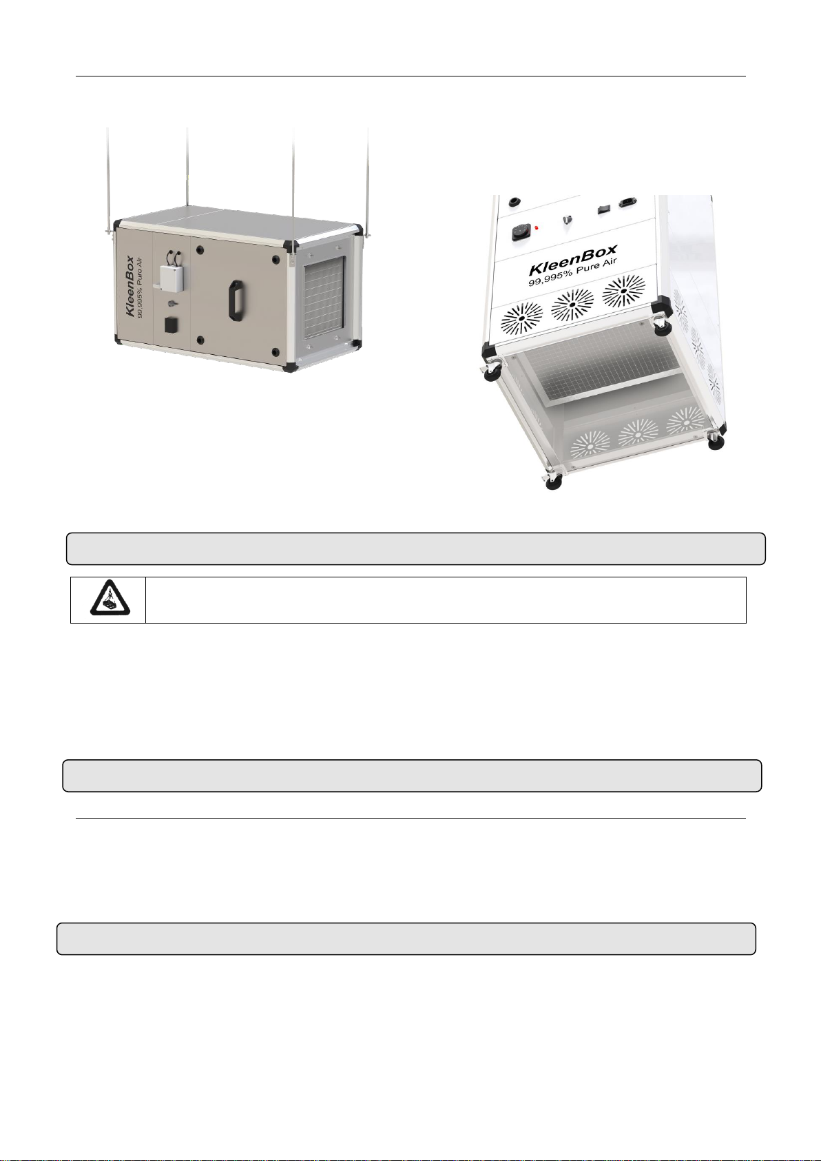
INSTALLATION ..................................................................................................................................................3
Power supply..................................................................................................................................................3
Control............................................................................................................................................................3
Fixings............................................................................................................................................................4
TRANSPORT AND STORAGE ..........................................................................................................................4
OPERATION INSTRUCTIONS ..........................................................................................................................4
Control board features....................................................................................................................................4
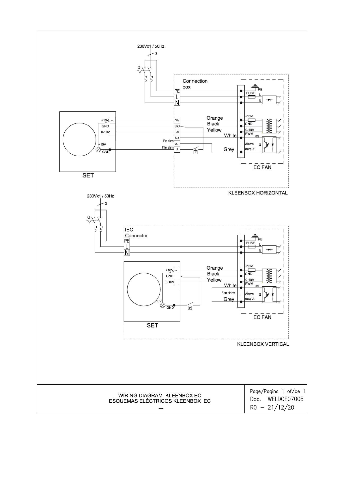
WIRING DIAGRAMS..........................................................................................................................................4
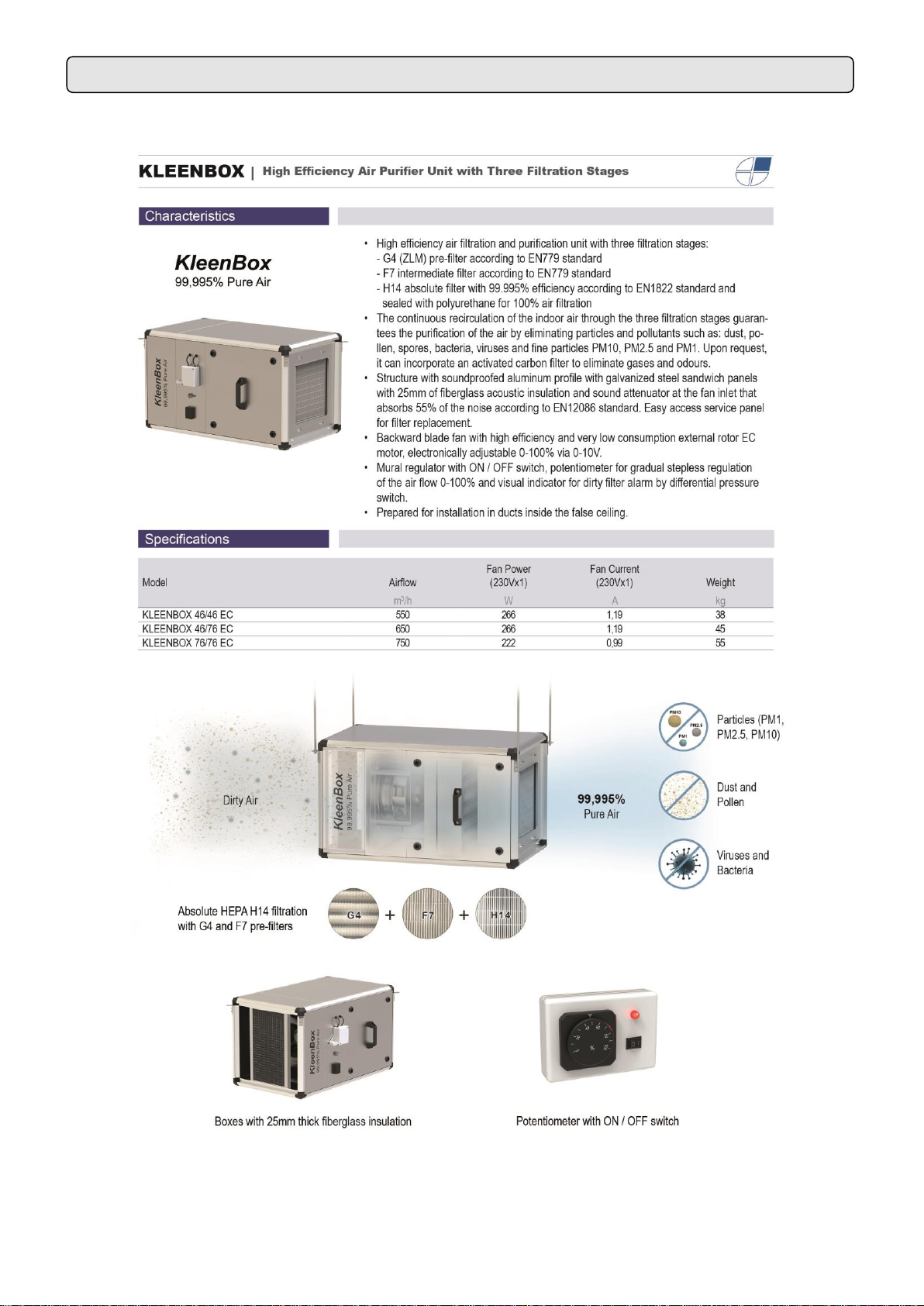
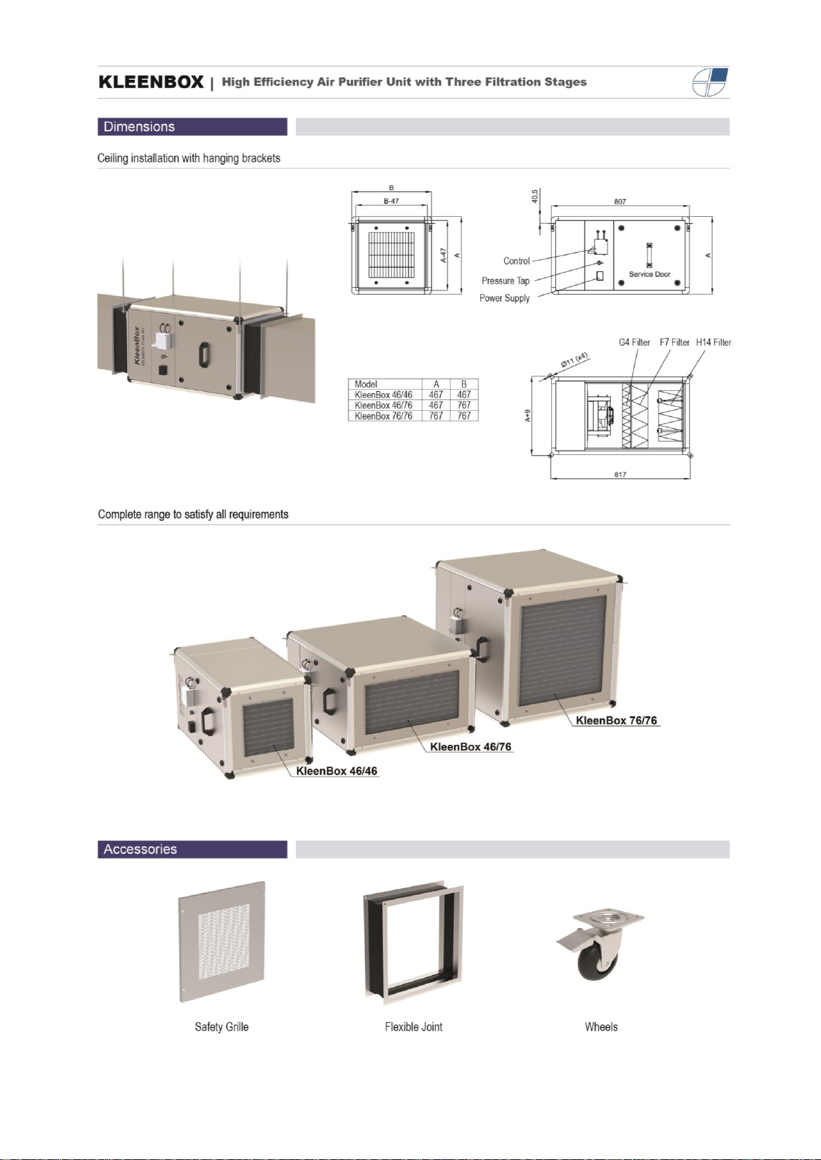
TECHNICAL DATA.............................................................................................................................................6
MAINTENANCE INSTRUCTIONS ...................................................................................................................10
Exterior cleaning...........................................................................................................................................10
Internal cleaning...........................................................................................................................................10
REPAIRS AND REEMPLACEMENTS .............................................................................................................10
Filter reemplacements..................................................................................................................................11
Fan replacement ..........................................................................................................................................13
ACCESSORIES................................................................................................................................................14
DECLARATION OF CONFORMITY.................................................................................................................15
Purifier identification.....................................................................................................................................16
GUARANTEE ...................................................................................................................................................16

3
INSTALLATION
HORIZONTAL
The horizontal models have four roof fixing points.
Keep in mind to asure a minimum distance to open
the service panel and to replace the filters. Depending
on the model, this distance is 500mm (Kleenbox
46/46 and Kleenbox 46/76) or 800mm (Kleenbox
76/76).
VERTICAL
Maintain 300 mm free of obstructions in the inlet
zone.
Assembly, connection and disconnection, electrical wiring and maintenance must be
carried out exclusively by qualified personnel, observing these instructions and in
accordance with the applicable standards. In case a special control is supplied, a
specific manual is attached that must be used for its operation and installation.
It is not necessary to remove the service panel to connect the equipment All the
connections (power and control) and necessary fixings are external (on the lateral of the
equipment). The equipment has a service panel to carry out repairs and replacements
(see “REPAIRS”section).
Power supply
HORIZONTAL
To connect the power supply on the horizontal
model, the user should find a black connection box
(placed on the lateral). Just connect single phase
230V to supply the fan.
VERTICAL
The vertical models include a plug&play wire which
should be connected to the equipment and to a
Shuckowall connector with electrical current.
Control
HORIZONTAL
There is a white connection box placed on the lateral,
next to the black power supply box. It is not needed
to open the service panel to connect the control.
It is necessary to connect the fan 0-10V regulation
and the dirty filter visual alarm (see wiring diagram
section).
VERTICAL
For the vertical model, the control is inbuilt in the
equipment and do not need any kind of installation.
230Vx1
Power Supply
Control
connection

4
TRANSPORT AND STORAGE
OPERATION INSTRUCTIONS
WIRING DIAGRAMS
Fixings
HORIZONTAL
Four fixing points placed on the four corners:
The moorings should be dimensioned according to
the weight of each model (see technical data
section). The installation can be done by threated
rods, tensioners or other supports not included.
VERTICAL
Four wheels to make easier the mobility. Two of
them includes breaks which allow the fix the
equipment and avoid the undesired displacements.
Attention! Heavy product.
Do not stand under the suspended equipment during transport or assembly.
Store in a dry place protected from the elements. If the packaging is open, cover the purifier to protect it from
dust. Do not step on or place heavy load son it to avoid damage to he material. Storage temperatura
between -20ºC and +40ºC.
When transporting the material, make sure that it is not damaged by the forklift (penetration of the fork in the
packaging). The instructions on the packaging must be observed.
Control board features
•ON/OFF: Includes a switch which cuts the fan power supply and immediately stops the equipment.
•Control 0-100%: Includes a 0-10V potentiometer which allows to regulate fan speed from 0 to 100%.
•Dirty filter visual alarm: by using a led indicator, the equipment informs the user that filters are dirty
and need to be replaced to keep the air clean.
The following diagrams are attached:
•Kleenbox horizontal and vertical. Diagram WELDOE07005

5

6
TECHNICAL DATA

7

8

9

10
MAINTENANCE INSTRUCTIONS
For safety, before cleaning, turn off the appliance using the controller.
It is forbidden to open the service panel (risk of electric shock and trapping in
fans).
Repairs must be carried out exclusively by authorized personnel.
The inside of the appliance must not be cleaned with water or steam.
Exterior cleaning
The Kleenbox HEPA filtration boxes do not need any kind of maintenance, except the housing cleaning for
the vertical models.
It is recommended to clean the inlet grille once a month. To do that, is very important to shut down the
equipment. If it keeps running, the fan could hover the wet dust causing damage to the rotor and covering the
filters, reducing its lifetime.
Cleaning the body of the purifier should be done with a damp cloth and a conventional detergent. Do not use
caustic or acid-containing detergents.
Internal cleaning
In models with perforated grille, it is advisable to clean the inside of the unit with a vacuum cleaner at least
once every 2 years (*), better to do it before winter, using qualified personnel.
It is recommended to clean the inside of the equipment frequently with the help of a vacuum cleaner. (*)
(*) These periods are indicative depending on the conditions of each installation. In places with a high
number of suspended particles it is desirable to increase the frequency of interior cleaning.
REPAIRS AND REEMPLACEMENTS
The assembly and the electrical connection must be carried out exclusively by specialized
personnel and observing these instructions.
Before carrying out any repairs, you must:
•Notify staff and indicate that work is in progress.
•Disconnect the power and protect the termal magnet (so that no one can
accidentally actuate it).
•Make sure there is no voltage on the purifier.
•Make sure that the fans have stopped.
•Use only original spare parts.

11
To open the service panel, use the key included with the equipment. The service panel has four closing
points that should be opened to take off the panel:
Once they are opened, take off the panel using the handle.
Filter reemplacements
Both models include a visual dirty filter alarm. When
the led is turned ON, the H14 HEPA filter must be
changed (the lifetime of HEPA filter is around 3.000
hours depending on the environment).
It is recommended to change the other two filters
after:
- G4 →500 working hours
- F7 →1.500 working hours

12
The G4 and F7 filters can be removed by pulling them once the service panel is removed:
G4 Filter
F7 Filter
After removing the G4 and F7 filters, there is enough space to take off the H14 filter. This one is fixed to the
housing by four wing nuts that should be untighten before remove the filter:
HEPA H14 Filter
To place the filters inside the equipment, follow the same steps but in reverse order: first, HEPA H14 filter,
secondly, F7 filter; and, the last one, G4 filter. Finally, close the service panel and close it using the key.

13
Fan replacement
For the fan replacement open the service panel and remove all the filters to get more working space and
avoid damages to them.
Straightaway, disconnect the fan wires. Depending on the model, we have:
Kleenbox Horizontal:
Power supply black box (faston)
0-10V regulation white box (terminals)
Kleenbox Vertical:
Plug&Play connector (faston)
0-10V Inbuilt potentiometer (borna)

14
Finally, unscrew the fan fixation. It has four hexagonal screws:
To assemble the new fan, follow the same steps in reverse order.
ACCESSORIES
Optional accessories not included for the Kleenbox installation:
Protection panel for HEPA filter
Flexible joint for ducts

15
DECLARATION OF CONFORMITY

16
Purifier identification
All air purifiers are identified by a unique serial number printed on
a label located on the inside of the service door. It also indicates
the model of the purifier and its technical characteristics (flow,
technical data of the fans).
It is essential to have this number to provide possible spare parts
or technical information for the purifier in question.
In case you detect errors or ambiguities in this manual, we Will be
happy to receive your feedback, it helps us to improve our
documentation even more.
Airtècnics reserves the right to change any of the specifications in
this manual.
GUARANTEE
Our warranty extends for one calendar year from the date of delivery. The guarantee is limited to repairing or
replacing from our warehouse the that eventually suffer failures attributable to production defects. Installation
costs are borne by the buyer. Products that, in our opinion, have been used improperly, handled incorrectly,
improperly installed, connected to voltages other than the nominal, modified or repaired by unauthorized
personnel, or that have suffered damage during transport, are excluded from any guarantee.
To validate the guarantee, it should be correctly filled and enclosed with the invoice that vouches for the buying date. If its manipulated,
it will lose all validity.
It is the buyer’s responsibility to take the necessary safety measures because in case of a failure or mistake in one of one our products,
no damages to third parties, sets, installations, or people will occur.
Guarantee draft
Purifier data:
Model: ............................................... Series number: .............................................................
Invoice date: ..................................... Invoice number: ............................................................
Buyer data:
Name: ................................................................................................................................................................
Address: ............................................................................................................................................................
Country: ………………………… Phone: ............................. Fax: ........................................................
Seller data:
Name: ................................................................................................................................................................
Address: ............................................................................................................................................................
Country: ………………………… Phone: ............................. Fax: ........................................................
Buyer signature and stamp Seller signature and stamp
This manual suits for next models
3
Table of contents
Other Airtecnics Air Cleaner manuals