AIRTEQ 8250 Series User manual

8250 SERIES
SLIDING DOOR OPERATOR


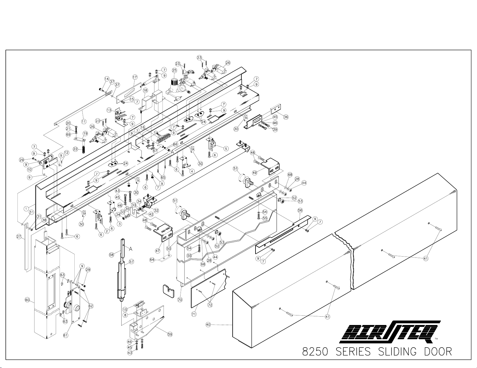
8250 SERIES SLIDING DOOR PARTS LIST
ITEM QTY PART NUMBER DESCRIPTION
1 1 *** BACKPLATE WELDMENT, L/C (SHOWN)
1 1 *** (OR) BACKPLATE WELDMENT, R/C
2 1 82008903 ASSY, LIMIT SWITCH, DBL, LH
3 1 820090 ASSY, SPEED REDUCING SWITCH, LH
4 1 820395 ASSY, SPEED REDUCING SWITCH, RH
5 1 82008904 ASSY, LIMIT SWITCH, DBL, RH
6 9 10001301 SCREW, CARRIAGE, 1/4-20 X 3/4
7 18 10002407 NYLOCK NUT, 1/4-20 ZINC PLATED
8 1 821017 ASSY, OUTSIDE GUIDE
9 23 10000706 FLAT WASHER, 1/4, TYPE B, REG.
10 1 820746 ASSY, BELL CRANK, L/C (SHOWN)
10 1 820747 (OR) ASSY, BELL CRANK, R/C
11 1 *** HORIZONTAL LINKAGE
12 1 10000901 COTTER PIN, 3/32 X 3/4
13 1 82008701 ASSY, LOCK SWITCH, L/C (SHOWN)
13 1 82008702 (OR) ASSY, LOCK SWITCH, R/C
14 1 10002504 SHOULDER SCREW, 5/16 DIA X 3/8 LG, 1/4-20
15 1 821016 ASSY, INSIDE GUIDE
16 1 100072 TERMINAL STRIP
17 1 82004301 ASSY, LOCK CYLINDER, L/C (SHOWN)
17 1 82004302 (OR) ASSY, LOCK CYLINDER, R/C
18 1 820021 LOCKBAR SLIDE BRACKET
19 1 820825 ASSY, BALANCE SPRING
20 1 10001003 SCREW, HEX, CAP, 5/16-18 X 5/8
21 1 10001407 LOCK WASHER, 5/16
22 1 10003201 LOCKBAR SPRING
23 6 10002303 SCREW, RH, SLOTTED, 6-32 X 1
24 6 10002402 HEX NUT, SEMS, 6-32
25 1 820751 ASSY, LOCK CYLINDER VALVE
26 2 82004601 ASSY, DOOR CYLINDER VALVE
27 1 *** VERTICAL LINKAGE
28 4 10001410 LOCK WASHER, 1/2
29 2 10002501 SHOULDER SCREW, 1/4 DIA X 3/8 LG, 10-24
30 4 10006209 SELF RETAINING NUT, SHORT, 3/8-16
31 2 10000704 FLAT WASHER, #10, TYPE B, REG.
32 1 *** ASSY, AIR CYLINDER
33 2* 10000501 FLAT WASHER, .447 I.D. X .880 O.D. X .030
34 2* 10000306 HEX JAM NUT, 7/16-20
35 1* 10000401 GROMMET
36 1 820072 DOOR STOP PLATE
37 2 10000707 FLAT WASHER, .344 I.D. X .688 O.D. X .060
38 1 10002404 HEX NUT, SEMS, 10-24
39 2 10001001 SCREW, HEX, CAP, 3/8-16 X 5/8, GRD 5
40 1 *** HOUSING COVER, L/C, (SHOWN)
40 1 *** (OR) HOUSING COVER, R/C
41 4 10003401 SCREW, TP, BH, 3/8-16 X 1
42 1 820218 DOOR DRIVE BRACKET
ITEM QTY PART NUMBER DESCRIPTION
43 2 10001006 SCREW, HEX, CAP, 3/8-16 X 1
44 4 10000210 HEX NUT, 1/2-13
45 4 10001408 LOCK WASHER, 3/8
46 4 10000708 FLAT WASHER, 3/8, TYPE B,REG.
47 1 820195 LOCK BRACKET, FRONT, L/C (SHOWN)
47 1 820193 (OR) LOCK BRACKET, FRONT, R/C
48 4 10001302 SCREW, CARRIAGE, 1/2-13 X 1-1/4
49 1 82019401 LOCK BRACKET, REAR, L/C (SHOWN)
49 1 82019201 OR) LOCK BRACKET, REAR, R/C
50 1 *** DOOR HANGER
51 2 82009801 ASSY, ROLLER
52 2** 10002803 WASHER, CONICAL, SERRATED, 5/8
53 2** 10000211 HEX NUT, 5/8-11
54 2** 10000707 FLAT WASHER, 5/16, TYPE B, REG.
55 2** 10001004 SCREW, HEX, CAP, 5/16-18 x1-1/2, W/NYLON PATCH
56 1 *** SWITCH ACTUATOR BRACKET
57 1 *** LOCKTUBE WELDMENT
58 1 *** LOCKBAR WELDMENT
59 1 820170 DOOR GUIDE BRACKET, L/C (SHOWN)
59 1 820181 (OR) DOOR GUIDE BRACKET, R/C
60 1 *** RECEIVER JAMB WELDMENT, L/C (SHOWN)
60 1 *** (OR) RECEIVER JAMB WELDMENT, R/C
61 1 *** ASSY, MANUAL OVERRIDE
62 4 10006402 SCREW, TP, FH, 10-24 X 3/4
63 4 10002405 SELF RETAINING NUT, 10-24
64 1 820108 NUT PLATE
65 2 10001000 SCREW, HEX HD, 6-20 X 1/2, TYPE AB
66 1 10002503 SHOULDER SCREW, 3/8 DIA X 1-1/2 LG, 5/16-18
67 1 820107 LOCKBAR SLIDE BEARING
68 4 10000710 FLAT WASHER, 1/2
69 1 10000707 FLAT WASHER, 5/16, TYPE B, REG.
70 1 *** DOOR GUIDE, L/C (SHOWN)
70 1 *** (OR) DOOR GUIDE, R/C
71 1 *** DOOR SKIRT
72 AS REQ'D 10003402 SCREW, TP, BH, 10-32 X 1/2
73 1 820826 WIRING HARNESS, MANUAL OVERRIDE (NOT SHOWN)
74 1 *** 8200 SERIES WIRING HARNESS (NOT SHOWN)
* PART OF ASSY, AIR CYLINDER ITEM #32
** PART OF ASSY, ROLLER ITEM #51
*** PART NUMBER ASSIGNED ON A JOB BY JOB BASIS.
8250-PL1.PM6


LUBRICATION, MAINTENANCE &
ADJUSTMENTS
8220 & 8250
SLIDING DOORS
3224 Mobile Highway Road ●Montgomery, Alabama 36108
(334)281-8440 ●FAX (334)286-4320
Lubrication and Adjustments – 8220/8250 3/2009 1

LUBRICATION and MAINTENANCE
1) Lubrication:
GREASE PIVOT POINTS
GREASE ALL SIDES
OF LOCKBAR
GREASE LOCK
PLATE (SIDES,
BOTTOM & SLOT)
GREASE SLIDE BEARING
(INSIDE & OUT)
OVERRIDE LINKAGE SLOT
& LOCKBAR ASSIST SPRING
GREASE OVERRIDE
MOVING PARTS
The lock plate mechanism, bell crank and
manual override mechanism should be well
lubricated, in the areas shown, with Super
Lube ® Multi-Purpose synthetic lubricant
grease.
Check for dried, caked or dust/debris
contaminated grease.
Wipe off grease in poor condition and
apply new grease
2) Roller Track
DO NOT lubricate the roller track.
To maintain smooth and quiet operation:
Keep roller track free of any
accumulation of dirt, dust, or other
debris.
If the track does not feel smooth:
Wipe track off with a lint free cloth or scouring pad (Scotch Brite® or equivalent.)
Do not use steel wool, sandpaper, or anything that may leave grit or fibers on the track.
3) Rollers
The roller assemblies are factory lubricated and sealed. They do not require lubrication.
If the track is clean and the rollers still do not roll smoothly, wipe rollers with a clean lint free cloth.
4) Bottom Guide Wear Pads
The door bottom is held in place by two Door Guide plates (each having a nylon wear pad.) Check for
excessive door movement in and out from the wall. 1/16th” movement at the bottom of the door is
acceptable. More than 1/16th” movement requires that the guides be adjusted and/or the wear pads be
replaced. Bottom Door Guide adjustment is detailed in the Mechanical Adjustments section, under
number 4 part b: “To Adjust Door Bottom Lateral Position.”
Lubrication and Adjustments – 8220/8250 3/2009 2
LOCK WASHER
DOOR
DOOR GUIDE
WEAR PADS
OUTSIDE
DOOR GUIDE
BOTTOM
DOOR GUIDE
WASHER
BRACKET
ADJUSTMENT
BOLTS
INSIDE
DOOR GUIDE
DOOR GUIDE
ANGLE
BOTTOM
DOOR GUIDE
LOCK
TUBE
DOOR
DOOR
DOOR
GUIDES
WEAR PADS
A
DOOR WITHNOTE:
A
HARDWARE FLUSH PULL
MOUNTED LOCK TUBE SIDE
REQUIRES A 3/16” GAP
1/8"
DOOR GUIDE
NOTCH
DOOR GUIDE
ANGLE
DOOR GUIDE
ANGLE

TO RAISE LOCKBAR
Manually Move Lockplate Away
From Cylinder: 8200 Series
or Motor: 7200 Series
Lockplate Shown In Locked Position
MECHANICAL ADJUSTMENTS
1) Lock Position Adjustment
The lockbar engages the door at the top and bottom in
both the open and closed positions.
The top locking points are determined by the door hanger
mounted front and rear Lock Brackets.
To Check the rear Lock Bracket position:
oMove the door to the fully closed position
oHold the door tight into the receiver column
oManually raise and lower the lockbar. (move the Lockplate slide by hand as shown.)
When raised and lowered the Lockbar should freely enter and exit the lock bracket notch and not bind or hang
If Lock Bracket interferes with the Lockbar raising or lowering or if the Lock Bracket notch presses on either
side of the Lock Bar then the Lock Bracket should be adjusted.
To Adjust Lock Bracket:
oAllow LOCKBAR to drop into the BOTTOM DOOR GUIDE Notch and into the LOCK BRACKET
oLoosen Lock Bracket Adjustment Nuts
oMove LOCK BRACKET to obtain the vertical engagement with the UPPER LOCKBAR LUG shown
oMove LOCK BRACKET horizontally so Lock Bar freely moves in Lock Bracket notch.
oThe LOCKBAR must move freely up and down in the LOCK BRACKET
Move the door to the full open position and repeat this procedure to position the Front Lock Bracket
Do not adjust the REAR LOCK BRACKET so high that the door can not close when the lockbar is unlocked
manually and then the lock bar release to rest on top of the bottom door guide angle as the door is moved (if
the lock bracket is too high it will run into the upper LOCKBAR LUG preventing the door from closing.)
Note: Because the door Drive Bracket is attached to the Front Lock Bracket, any adjustment of the Front
Lock Bracket must be followed by an adjustment of the door drive bracket.
Door Hanger
Drive Bracket
(Fully Driven Models)
Adjust for
Clearance
On Slot Sides
Lock Bar
Lock Bracket
Adjustment Nuts
Lock Bracket
Drive Bracket
Adjustment Bolts
UPPER
LOCKBAR
LUG
⅛”LOCK
BRACKET
Lubrication and Adjustments – 8220/8250 3/2009 3

TO RAISE LOCKBAR
Manually Move Lockplate Away
From Cylinder: 8200 Series
or Motor: 7200 Series
Lubrication and Adjustments – 8220/8250 3/2009 4
Drive Bracket
C
y
linder Rod
End Nut
Front
Lock Bracket
Drive C
y
linder
Drive Bracket
A
d
j
ustment Bolts
A
fter Adjustment DO
NOT Crush Grom-
met When Tight-
ening End Nut
Lockplate Shown In Locked Position
2) Door Drive Bracket Adjustment
The Door Drive Cylinder rod must not be side loaded.
One test for a side load condition:
oMove the door to the open/locked position.
oManually unlock the door by moving the Lock Plate as shown.
oWith the LOCKBAR lifted, manually move the door towards
the closed position. The door should move easily and may even start to move by itself, this is normal.
oApproaching the fully open position, the effort required to move the door should not increase at all.
oPossible conditions present if door movement becomes restricted approaching the fully open position:
Severely side loaded cylinder rod (Drive Bracket Adjustment required)
Vertically misaligned door - either rubbing the cover or bottom door guide slot (Door Height
Adjustment required, followed by a Drive Bracket Adjustment)
Horizontally misaligned door – Robbing the lock column or cover (Door Lateral Position
Adjustment required, followed by a Drive Bracket Adjustment)
Dirty roller track (Roller Track requires cleaning)
Door Skirt is dragging a high spot in the floor (Door Skirt Adjustment required)
To Adjust the Drive Bracket:
oLoosen the Drive Bracket Adjustment Bolts
oSlightly loosen Cylinder Rod End Nut (allows cylinder rod to slide freely in the drive bracket slot).
oMove the door to the open/locked position.
oTypically the cylinder will push the bracket out to the end of the slot. Move bracket by hand in & out
and back & forth until the bracket / cylinder feels ‘free.’
oSecure the Drive Bracket Adjustment Bolts - ensure the drive bracket does not move while tightening
the bolts.
oTighten the Cylinder Rod Nut with the door in the open position. NOTE: Do not over tighten the
cylinder rod nut and crush the rubber grommet!
oDO NOT bind the cylinder rod
oVerify proper cylinder rod alignment (No Side Loading on Cylinder)

BOTTOM
DOOR GUIDE
LOCK
TUBE
DOOR
DOOR
DOOR
GUIDES
WEAR PADS
NOTE:
A
DOOR
W
ITH
A
HARDWARE FLUSH PULL
MOUNTED LOCK TUBE SIDE
REQUIRES A 3/16” GAP
1/8"
DOOR GUIDE
NOTCH
DOOR GUIDE
ANGLE
DOOR GUIDE
ANGLE
3) Door Height Adjustment
Improper door height may result in the door hanger
rubbing on the cover, or the bottom door guide angle
rubbing on the top or bottom of the bottom Door
Guide Notch.
There are two height adjustment bolts, one for each
side of the door. One complete turn will move the door
up or down 1/16".
Turn the bolt clockwise to raise the door and
counterclockwise to lower the door.
When making height adjustments, first determine how
much change is needed, loosen the axle nut, turn the
adjustment bolt the appropriate amount, then tighten
the axle nut securely and check for proper clearances.
Note: After any adjustment is made to the door height or the door in or out, re-adjustment of the drive cylinder to
the drive cylinder bracket is required. (See Item 2 on preceding page)
Drive Bracket
C
y
linder Rod
End Nut
Front
Lock Bracket
Drive C
y
linder
Drive Bracket
A
d
j
ustment Bolts
A
fter Adjustment DO
NOT Crush Grom-
met When Tight-
ening End Nut
1/2"
Wrench
Door Up/Down Adjustment
Lower
Door
Raise Door
Lubrication and Adjustments – 8220/8250 3/2009 5

4) Door Lateral Position Adjustment
The sliding door should clear the lock tube and the sides of the
receiving pocket by a minimum of 1/16"
If the door rubs on any of these surfaces, or if the door hanger
rubs on the cover, adjustment is required.
Note: After any door position adjustment is made. The Door
Drive Bracket / Cylinder Alignment must be re-adjusted.
a) To Adjust Door Top Lateral Position:
The top of the door can be adjusted at both the front and rear
edge of the door. Loosen the appropriate axle nut.
While holding the nut with a wrench, turn the axle with a 1/4"
Allen wrench. Each complete turn of the axle will move the door
approximately 1/8". Turn the axle clockwise to move the door
away from the wall and counterclockwise to bring the door c
to the wall. Tighten the axle nuts securely after adjustm
b) To Adjust Door Bottom
loser
ent.
Lateral Position
side of the bottom door
gainst the door guide angle, move the door and guides to the desired position.
tom door guide angle travels smoothly through the guides throughout limits of door
door Gap throughout travel (Lock column, wall and receiver pocket
After any door position adjustment is made. The Door Drive Bracket / Cylinder Alignment must be re-adjusted.
Loosen the two bolts on the bottom
guide mounting bracket.
While holding the guides a
(a 1/16” shim may be used to help space guides and Bottom Guide Angle properly)
Tighten the bolts
Check that the bot
travel
Check
BOTTOM
DOOR GUIDE
LOCK
TUBE
DOOR
DOOR
DOOR
GUIDES
WEAR PADS
NOTE:
A
DOOR
W
ITH
A
HARDWARE FLUSH PULL
MOUNTEDLOCKTUBESIDE
REQUIRES A 3/16” GAP
1/8"
DOOR GUIDE
NOTCH
DOOR GUIDE
ANGLE
DOOR GUIDE
ANGLE
Axle Nut
15/16" Wrench
1/4" T-Handle
Allen Wrench
Roller Axle
Move Door Out
Move Door In
Wrench to Prevent
Axle Nut From Turning
During In/Out Adjustments
Door In/Out Adjustment
Lubrication and Adjustments – 8220/8250 3/2009 6

Door Stop
Left Close Configuration Shown
Doo
r
Han
g
e
r
Door Stop
Bolts
5) Rear Door Stop Adjustment
The rear door stop locates the door for the proper locked open
position.
If the lock bar does not drop completely and freely into the bottom door
guide notch in the locked open position, the rear door stop MAY need
adjustment
NOTE two other conditions should also be checked if the door is not freely locking in the OPEN position:
1. The door MAY be hanging out of plumb (i.e. one side higher than the other). This condition will
cause the top end of the door to be misaligned with the bottom end. The door should be vertically
adjusted to allow the bottom door guide notch to freely engage the lock bar in the open position.
Depending on installation conditions (receiver not plumb, lock column not plumb, and/or door out
of square) there may need to be some compromise between door plumb and making the device
work.
2. The front (TOP) lock bracket horizontal position may also need adjustment
3. Any door position or front lock bracket adjustment requires that the Door Drive Bracket / Cylinder
Alignment must be re-adjusted
To Adjust the Rear Door Stop:
Loosen the Door Stop Bolts.
Move the door to the position where the lock bar drops completely & freely into the bottom door guide slot.
Slide the Door Stop up against the door hanger at that door position.
Provisionally secure the Door Stop in that position
Check for proper operation of the device (freely locking in both the Open and Closed positions.)
When device operates properly, torque the Door Stop Bolts to 75 ft/lbs.
Lubrication and Adjustments – 8220/8250 3/2009 7

Lubrication and Adjustments – 8220/8250 3/2009 8
PNEUMATIC ADJUSTMENTS
1) Drive Cylinder Pressure:
The drive cylinder pressure is adjusted by a pressure
regulator. Increasing drive cylinder pressure will
increase the door’s travel speed.
To increase Drive Cylinder Pressure:
oTurn Pressure Adjustment knob clockwise
To decrease Drive Cylinder Pressure:
oTurn Pressure Adjustment knob:
Counterclockwise below desired pressure
Clockwise up to desired pressure.
Cylinder drive force is gauge pressure shown
multiplied by 1.23: (i.e. 32.5 psig x 1.23 =40 lbs)
NOTE: Dirt particles in the air stream may lodge
under the pressure regulator diaphragm during door operation. This condition can result in a constant air
"bleed off" that is usually clearly audible. To correct this problem:
oTurn off the air supply to the door.
oDisassemble, clean and re-assemble the pressure regulator
oThe pressure regulator body does not need to be removed from the valve manifold.
oCheck main air system particle filter element(s) at the compressor location
A dirty filter element can permit dirt particles into the line air stream.
oTurn on air supply to the door
2) Lock Cylinder Unlock Speed (Lock bar Unlocking Speed & Noise-“Bang”):
To increase the lock cylinder speed (and raise Lock Bar Unlocking noise/bang):
oLoosen the LOCK CYLINDER UNLOCK SPEED CONTROL jamb nut
oTurn the LOCK CYLINDER UNLOCK SPEED CONTROL adjustment screw OUT (counter clockwise) slightly
oSecure the LOCK CYLINDER UNLOCK SPEED CONTROL jamb nut
To decrease the lock cylinder speed (and reduce Lock Bar Unlocking noise/bang)
oLoosen the LOCK CYLINDER UNLOCK SPEED CONTROL jamb nut
oTurn the LOCK CYLINDER UNLOCK SPEED CONTROL adjustment screw IN (clockwise) slightly
oSecure the LOCK CYLINDER UNLOCK SPEED CONTROL jamb nut
Changes done with the LOCK CYLINDER UNLOCK SPEED CONTROL do not affect the unlocking force exerted
by the lock cylinder on the lock bar. The LOCK CYLINDER UNLOCK SPEED CONTROL does affect the speed
and the corresponding momentum of the lock bar as it raises.
The Lock Cylinder Speed should be adjusted until the lock bar can be clearly heard when unlocking but no
more. Allowing the lock bar to unlock at maximum speed (and noise) puts excessive strain on the lock bar
roller bearing shoulder bolt and should be avoided.
3) Door Deceleration Control
The deceleration controls slow the door down a few inches prior to end of travel for smooth, consistent locking in
the open and closed positions. If a door impacts the receiving column or rear door stop too hard or travels too
slowly in the last few inches of travel, the deceleration control for the door direction in question (Open or Close)
must be adjusted:
To reduce the end of travel speed (to correct door ramming the receiving column or rear door stop):
oTurn the associated direction’s Deceleration Adjustment knob clockwise.
To increase the end of travel speed (to correct door traveling too slowly in the deceleration range):
oTurn the associated direction’s Deceleration Adjustment knob counter clockwise.
Note: If a door “bounces” – (briefly reverses direction) when a deceleration switch is initially contacted:
oDrive cylinder pressure is likely adjusted too high: Decrease drive cylinder pressure (step 1 above)
oAdjust Deceleration Control for appropriate door deceleration speed
Drive Cylinder
Pressure Adjustment
(CW Increase, CCW Decrease)
Lock Cylinder
Air Connection
Main Air Supply
Connection
Lock Cylinder
Unlock Speed Control
(CW Slower
CCW Faster)
RMERS
Air Connection
Door Open
Deceleration Adjustment
(CW Slower, CCW Faster)
Drive Cyl.
Nose Air
Connection
Drive Cylinder
Rear Air
Connection
Drive Cylinder
Pressure Gauge
Door Close
Deceleration Adjustment
(CW Slower, CCW Faster)

Lubrication and Adjustments – 8220/8250 3/2009 9
ELECTRICAL ADJUSTMENTS
LS2A & LS2B
LS1A & LS1B
LS4A & LS4B
LS6 LS3A & LS3B
LS5
8200 Series
Switch Locations
LEFT CLOSE DOOR
(Shown Closed)
1) Secure/Unsecure Indication
Device Status indication is controlled by the Lock
Bar Down Status Switches (LS2A & LS2B) and the
Door Position Switches, Door Closed Status
(LS4A & LS4B) and Door Open Status Switches
(LS3A & LS3B). Both the Door Closed Status
Switch (LS4B) and the Lock Bar Down Status
Switch (LS2A) must be made in order to generate
a secure indication. If either switch is not made,
an insecure indication is provided.
SWITCH ACTUATOR
BRACKET
a) Lock Bar Down Status Switches (LS2A & LS2B)
The Lock Bar Down Status Switches are located in front and near the bottom of the lock mechanism.
Only when the lock bar is at its lowest point should these switches be depressed.
To adjust the Lock Bar Down Status Switch Position:
Place the door in the closed/locked position.
The lock bar lifting pin should be at the bottom end of the Z shaped slot in the horizontal lock slide.
Slots are provided in the mounting bracket for adjustment.
Loosen the screws securing the Lock Bar Down Status Switches.
Lower the switches away from the lifting pin.
Then slowly raise the switches until the contacts close (switches will click at this point).
Secure the screws attaching the Lock Bar Down Status Switches.
b) Door Closed Position Status Switches (LS4A & LS4B)
These Door Closed Position Status Switches are ganged together on a bracket mounted to the device tray near the
receiving column/channel. These Status Switches signal the lock bar to drop when the door reaches the fully
closed position. They should be fully depressed by the SWITCH ACTUATOR BRACKET when the door is in the
closed/locked position. Pulling the door against the Lock bar (away from the receiving column/channel) should not
release either of these Door Closed Position Status Switches.
To adjust the Door Position Status Switch:
Loosen the switch bracket mounting nut that secures switch bracket to the device tray.
Position the door in the closed/locked position.
Hold the door tightly against the lock bar towards the open position.
Position the switches so that they are fully depressed (switch arms fully activated)
Switch Bracket should not at an angle, both switches should make at the same time
Tighten the switch bracket mounting nut.
2) Lock Bar Unlocked Status Switches (LS1A & LS1B)
The Lock Bar Unlocked Status Switch engages the door drive cylinder after the lock bar is fully raised when the
control panel has provided a door open or door close signal. These switches are located in front of and near the top
of the lock mechanism. These Status Switches should be depressed when the lock bar is at the top of its travel.
To adjust the Lock Bar Up Status Switch Position:
Loosen the screws securing the Lock Bar Up Status Switches.
Manually pull the horizontal lock plate to the fully unlocked position, lock bar fully raised
Slots are provided in the mounting bracket for adjustment.
Raise the switches away from the lifting pin.
Then slowly lower the switches until the contacts close (switches will click at this point).
Secure the screws attaching the Lock Bar Up Status Switches.

Lubrication and Adjustments – 8220/8250 3/2009 10
3) Fully Open Switches (LS3A & LS3B)
These Door Fully Open Position Status Switches are ganged together on a bracket mounted to the device tray near
the rear door stop of the device. These Status Switches signal the lock bar to drop when the door reaches the fully
open position. They should be fully depressed by the SWITCH ACTUATOR BRACKET when the door is in the fully
open/locked position.
To adjust the Door Position Status Switch:
Loosen the switch bracket mounting nut that secures switch bracket to the device tray.
Position the door in the opened/locked position.
Hold the door tightly against the lock bar towards the closed position.
Position the switches so that they are fully depressed (switch arms fully activated)
Switch Bracket should not at an angle, both switches should make at the same time
Tighten the switch bracket mounting nut.
4) Deceleration Switches (LS5 & LS6)
There are two deceleration switches: LS5 signals open deceleration and LS6 controls signals close deceleration.
The open deceleration switch (LS5) is located above and near the center of the door when the door is in the open
position. The close deceleration switch (LS6) is located above and near the center of the door when the door is in
the closed position. The deceleration switches deactivate a solenoid valve, which slows down the door travel speed
toward the end of the door’s range of motion. These switches are adjusted in conjunction with the door
deceleration flow control valves.
If the door impacts the receiving column or rear door stop too hard, or if the door moves too slowly at the
end of its travel, first refer to "Door Deceleration Control" in Pneumatic Adjustment section.
If proper deceleration cannot be achieved pneumatically, adjust the position of the deceleration switch.
The position of the deceleration switch determines the point at which the door begins to slow.
To adjust a deceleration switch position:
Loosen the switch bracket mounting nut that secures the deceleration switch bracket to the device tray.
Slide the bracket to the desired position in device tray mounting slot and tighten the nut.
oMoving the switch towards the center of the device will cause the door to decelerate sooner.
oIncreasing the deceleration length will increase the time it takes to open or close the door.
oDecreasing the deceleration length too much can result in the door "bouncing" at the end of its
travel or impacting the receiving column or rear door stop too severely.
Check that the Deceleration switch arm is riding smoothly onto the SWITCH ACTUATOR BRACKET and is
not interfering with any door or roller hardware. If interference is detected adjust the switch position to
remove the interference.

BOTTOM GUIDE
ANGLE
LOCK TUBE
NOTCH
BOLTS
DOOR
WEAR PADS
GUIDES
Fig. B
Fig. C
LOCK CYLINDER
SPEED ADJUSTMENT
DRIVE PRESSURE
ADJUSTMENT

CLEARANCE
ALL SIDES
LOCKBAR
DOOR DRIVE BRACKET
(ROD CYLINDER MODEL
ONLY)
LOCK BRACKET
Fig. E
Fig. D
DECELERATION
ADJUSTMENT
This manual suits for next models
1
Table of contents
Popular Door Opening System manuals by other brands

GEZE
GEZE UFO-NT IP Wiring diargam

Vimar
Vimar ELVOX 0930/000.04 Wiring diagram

Assa Abloy
Assa Abloy Corbin Russwin PED5000 DB Series installation instructions

Falcon
Falcon SC80 installation instructions

Assa Abloy
Assa Abloy SECURITRON DEM680E Series Installation & operating instructions

Dorex
Dorex DX1 PV/FV installation instructions

CornellCookson
CornellCookson SGHN4-100 Series Installation instructions and operation manual

CAME
CAME 803XA-0320 instructions

Dorma
Dorma TS93 T installation guide

Vision
Vision ZG 8101 IN Installation & operation manual

GEZE
GEZE TS1000 installation instructions

Nice
Nice STX KIT Instructions and warnings for installation and use