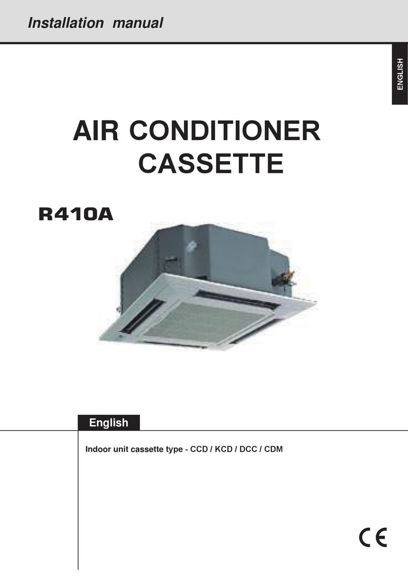
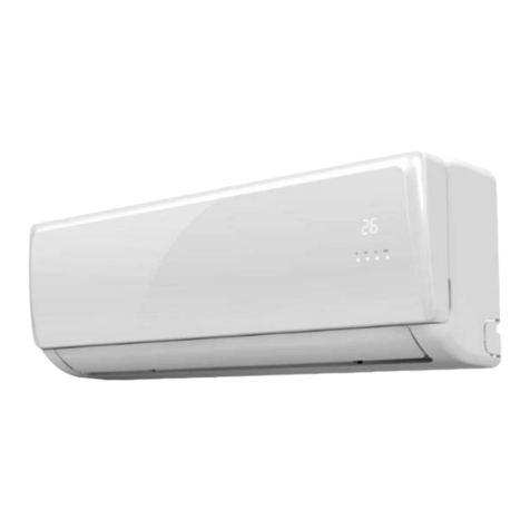
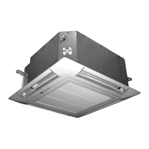
Airwell SXV009 User manual
Other Airwell Air Conditioner manuals

Airwell
Airwell ZDAA-2040-09M25 User manual
Airwell
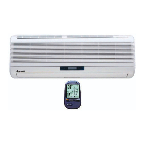
Airwell DLS series User manual
Airwell
Airwell FLO 7 N User manual
Airwell
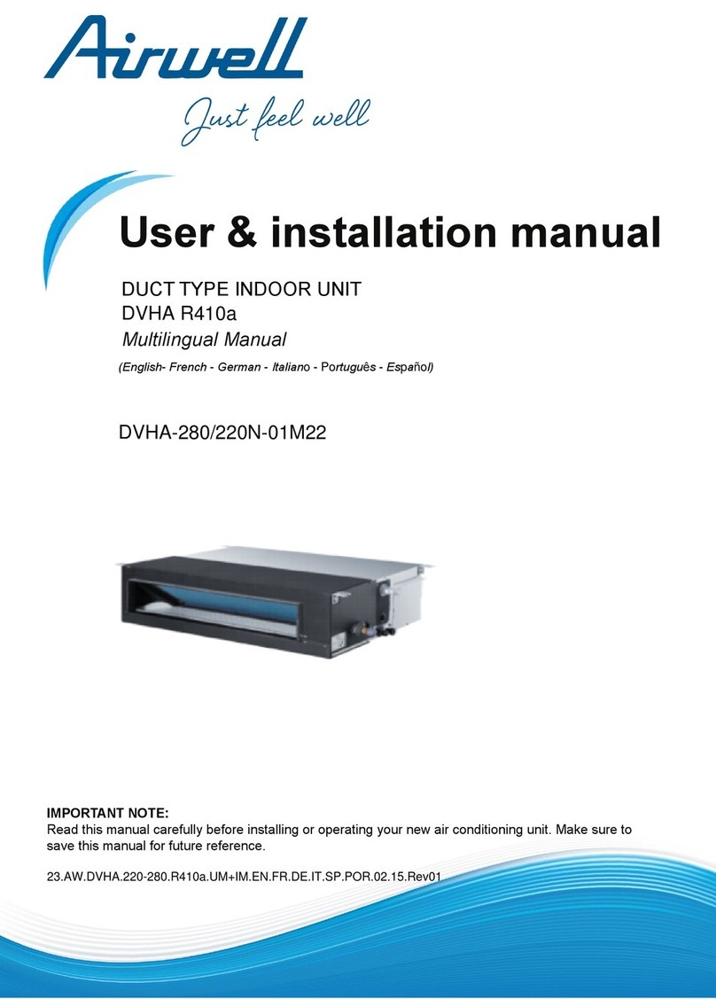
Airwell AW-HDL012-N91 User manual
Airwell
Airwell DVHA-220N-01M22 Guide
Airwell
Airwell AWSI-HJD009-N11 User manual

Airwell
Airwell CDMX-035N-09M25 User manual
Airwell
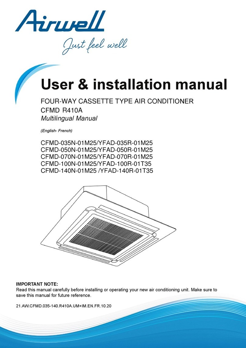
Airwell CFMD-035N-01M25 Guide

Airwell
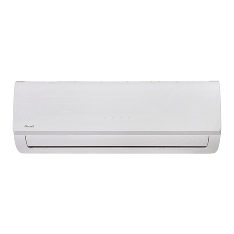
Airwell GC 9 DCI Nordic User manual
Airwell
Airwell HDLA R32 Series Guide

Airwell
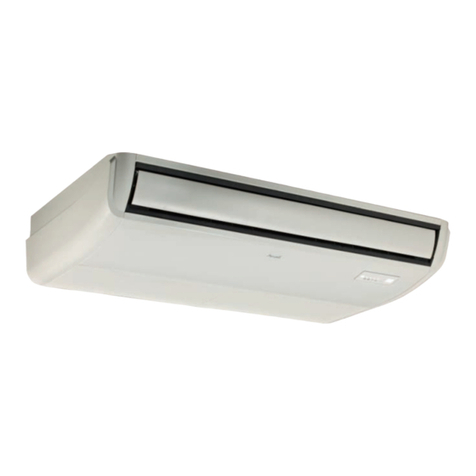
Airwell KXV021 User manual
Airwell
Airwell Aqu@Scop Advance R410A User manual
Airwell
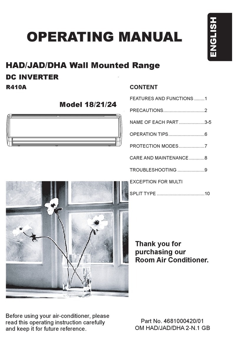
Airwell 18 User manual

Airwell
Airwell CK DC Series User manual
Airwell
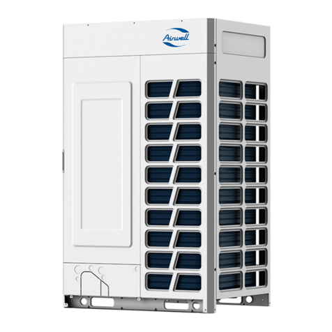
Airwell ODU VRF VVEA Series User manual
Airwell
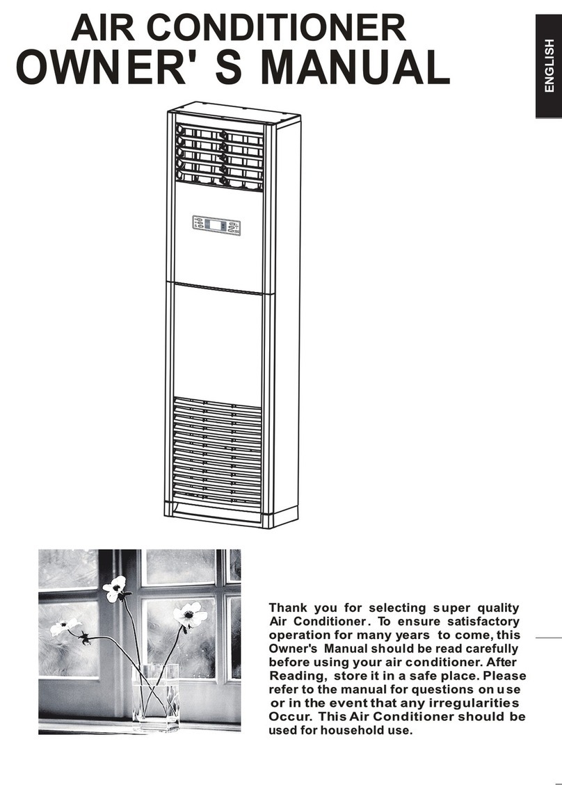
Airwell SBF User manual

Airwell
Airwell Aqu@Scop Advance R410A User manual

Airwell
Airwell CDMX-022N-09M25 Guide

Airwell
Airwell FBD 045 User manual
Airwell
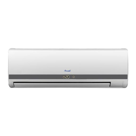
Airwell ST-NKFL 7R User manual
Popular Air Conditioner manuals by other brands

CIAT
CIAT Magister 2 Series Installation, Operation, Commissioning, Maintenance

Bestron
Bestron AAC6000 instruction manual

Frigidaire
Frigidaire FFRE0533S1E0 Use & care guide

Samsung
Samsung AS09HM3N user manual

Frigidaire
Frigidaire CRA073PU11 use & care

Soleus Air
Soleus Air GB-PAC-08E4 operating instructions

McQuay
McQuay MCK020A Technical manual

Webasto
Webasto Frigo Top 25 DS Instructions for use

Frigidaire
Frigidaire FAZ12ES2A installation instructions

Mitsubishi Electric
Mitsubishi Electric MSC-GE20VB operating instructions

Mitsubishi Electric
Mitsubishi Electric PLA-M100EA installation manual

Daikin
Daikin Split Sensira R32 Service manual
