manuals.online logo
Brands
  1. Home
  2. •
  3. Brands
  4. •
  5. Airwell
  6. •
  7. Controllers
  8. •
  9. Airwell AHU V2-7ACELH040 User manual

Airwell AHU V2-7ACELH040 User manual

•Please read this operation manual before using the air conditioner.
•Please keep this manual carefully and safely.
CONTENT
Parts and Functions............................................................ 1
Operation............................................................................ 5
Wired Controller Wiring Instruction....................................13
Wired Controller
Operation & Installation Manual
AHU V2-7ACELH040
23.AW.7ACELH040.UM.IM.EN.08.17.V01
1
Parts and Functions
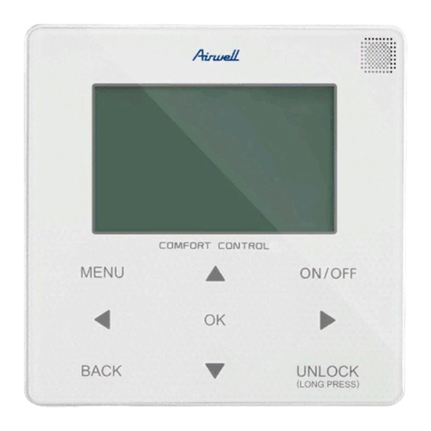
Appearance
2
Parts and Functions
Interface Display
Time Year/month/day/hour/min./sec./week
Operation status OFF/mode
Fan High/medium/Low
Setpoint temp. Adjusting range is 16 to 30°C. The
adjusting accuracy is 0.5°C
Error code Real time display the error code
Ambient temp. Ambient temp. of unit
3
Parts and Functions
Button
Button icon Function
ON/OFF
Press this button to turn on/off
the unit. It will display green after
turned on.
Mode Press this button to adjust
operation mode
UP Press this button to adjust fan
speed or adjust function
Down Press this button to adjust fan
speed or adjust function
Increase Press this button to adjust the
temp. or the other parameters
Decrease Press this button to adjust the
temp. or the other parameters
ok Press this button to conrm
Menu Press this button to enter menu
function
4
Parts and Functions
Button icon Function
back
Press this button to return back the
previous screen. Hold this button
for 5s to return back to the main
screen directly.
5
Function
Press [ ] to enter the menu interface:
Press [ / ] button to adjust function, press
[ ] button to conrm
1. Time and date setting:
6
Press [ / ] button to adjust function, press
[/ ] button to adjust the parameter values.
For multi units in the system, press [ / ] button to adjust
the unit.
2. System Status:
Function
7
Function
3. System setting:
8
Press [ / ] button to adjust function and
press [ ]  button to conrm. As a result, the selected 
function will be displayed in black. Press [ / ] button to
adjust the parameter values. The system setting function is as
follows:
①Fan setting. This function is used to set fan speed range,
including High/medium/Low; High/Low; High.
②Mode setting. Select this function and press [ ] button
to enter this function:
Function
9
Under this function, each mode can be set.
③Revise overheat: 5 groups of parameters can be adjusted.
④Revise overcool: 5 groups of parameters can be adjusted.
⑤Anti cold air temp. compensation: 5 groups of parameters
can be adjusted.
⑥Power off memory of unit: ON/OFF can be adjusted.
⑦ Ambient temp. compensation in heating: -10~10°C can be
adjusted.
⑧Ambient temp. compensation in cooling: -10~10°C can be
adjusted.
⑨EEV full open/close: ON/OFF/Normal can be adjusted.
10 Thermo.ON opening: 5 groups of parameters can be
adjusted.
11 Thermo.ON opening: 5 groups of parameters can be
adjusted.
Function
10
Note:
[/ ] button is used to adjust the unit when the function is
not conrmed by [ ] button.
4. Error code inquiry:
Function
13 Thermo.ON lower limit: 5 groups of parameters can be
adjusted.
11
Press [ / ] button to adjust function, press
[ ] button to inquire the Current/ Historical error.
Press [ / ] button to turn the page to inquiry
more errors in Current/ Historical error interface.
Function
12
5. Display setting:
Screen brightness: 30%, 50%, 60%, 80%, 100% adjustable.
Screen saver setting: 00s, 15s, 30s, 60s adjustable . 00s
means the backlight is always bright.
Function
13
Wired Controller Wiring Instruction
Cautions:
1. The normally used temp. range of wired controller: -10~60°C
2. The wiring of wired controller:
The length of the wiring The size of the wiring
≤ 250m 0.75mm2×4 shielded wire
The length of the wiring is not allowed to exceed 250m. If it
exceeds 250m, it must be equipped with an adapter.
14
Wired Controller Wiring Instruction
Dimension Drawing
15
Wiring connection method
Wired Controller Wiring Instruction
1.Push down and remove the pendant from the bottom of the
wired controller, install the pendant on the 86 cassette.
16
2. Connect the wiring as follows.
Wiring color Line terminal
White B
Green A
Black GND
Red 12V
Wired Controller Wiring Instruction
WARNING :
The design and specifications are subject to change without prior
notice for product improvement. Consult with the sales agency or
manufacturer for details.
ATTENTION :
Le design et les données techniques sont donnés à titre indicatif
et peuvent être modifiés sans préavis.
22.AW.RWV06.UM.IM.EN.12.
AIRWELL RESIDENTIAL SAS
10,Rue du Fort de Saint Cyr,
78180 Montigny le Bretonneux - France www.
airwell.com
01.V01
23.AW.RWV10.UM.IM.EN.08.14.V01

Other Airwell Controllers manuals

Airwell WELLEA MONO SPLIT A R32 User manual

Airwell

Airwell WELLEA MONO SPLIT A R32 User manual

Airwell CCM30/BKE-A Operating instructions

Airwell

Airwell CCM30/BKE-A Operating instructions

Airwell RWV01 User manual

Airwell

Airwell RWV01 User manual

Airwell RCW21 User manual

Airwell

Airwell RCW21 User manual

Airwell RCW30 User manual

Airwell

Airwell RCW30 User manual

Airwell RCW22 Installation instructions

Airwell

Airwell RCW22 Installation instructions

Airwell RWV04 User manual

Airwell

Airwell RWV04 User manual

Airwell RCW30 User manual

Airwell

Airwell RCW30 User manual

Airwell RWV03 User manual

Airwell

Airwell RWV03 User manual

Popular Controllers manuals by other brands

Endress+Hauser RA33 Brief operating instructions

Endress+Hauser

Endress+Hauser RA33 Brief operating instructions

Sony MB-8N user guide

Sony

Sony MB-8N user guide

Omron E5ED-8 Series instruction manual

Omron

Omron E5ED-8 Series instruction manual

Temptek G-500 Series instruction manual

Temptek

Temptek G-500 Series instruction manual

Heat Controller DXM2 Application and instruction manual

Heat Controller

Heat Controller DXM2 Application and instruction manual

Lian-Li BORA120R-1 user guide

Lian-Li

Lian-Li BORA120R-1 user guide

Salus PC11W manual

Salus

Salus PC11W manual

3Ware 720-0192-00 Guide

3Ware

3Ware 720-0192-00 Guide

Asparion D700 manual

Asparion

Asparion D700 manual

BIFFI ALGA Series Installation, operation and maintenance manual

BIFFI

BIFFI ALGA Series Installation, operation and maintenance manual

Siemens SIRIUS 3RW30 manual

Siemens

Siemens SIRIUS 3RW30 manual

Zennio MAXinBOX 16 Plus Technical documentation

Zennio

Zennio MAXinBOX 16 Plus Technical documentation

Lincoln Electric NA-3S Operator's manual

Lincoln Electric

Lincoln Electric NA-3S Operator's manual

Siemens PXC Series installation instructions

Siemens

Siemens PXC Series installation instructions

EURONOM ExoTrol MULTI C Installation and user guide

EURONOM

EURONOM ExoTrol MULTI C Installation and user guide

Omron NE1A-SCPU02 instruction manual

Omron

Omron NE1A-SCPU02 instruction manual

AIMS Power SCC-20A MPPT Installation and operation manual

AIMS Power

AIMS Power SCC-20A MPPT Installation and operation manual

ATTO Technology SC 5550E Installation and operation manual

ATTO Technology

ATTO Technology SC 5550E Installation and operation manual

manuals.online logo
manuals.online logoBrands
  • About & Mission
  • Contact us
  • Privacy Policy
  • Terms and Conditions

Copyright 2025 Manuals.Online. All Rights Reserved.