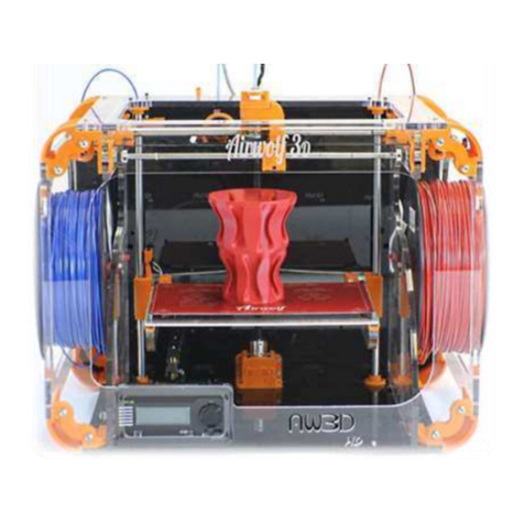
Airwolf 3D HD2x User manual


TABLE OF CONTENTS
INTRODUCTION .....................................3
TECHNICAL SPECIFICATIONS ...............4
BOX CONTENTS .....................................5
PARTS DIRECTORY ................................6
HOW IT WORKS .....................................7
VIKI LCD SCREEN ...................................8
VIKI LCD SCREEN LAYOUT .....................9
VIKI LCD: HOW TO ................................10
RAMBO DRIVER INSTALLATION ..........11
SOFTWARE INSTALLATION: CURA ......16
SOFTWARE INSTALLATION:
REPETIER HOST ...................................20
5 STEPS TO 3D PRINTING ....................22
SLICING PROCESS ................................23 2
GUIDE TO 3D PRINTING .......................24
1. FILE CREATION ......................24
2. CREATING STL .......................24
3. FILE CLEANUP (NETFABB) ....25
4. SLICING ..................................26
CURA INTERFACE ......................27
4a. SINGLE HEAD PRINTING .....29
4b. SINGLE HEAD PRINTING
WITH SUPPORT .........................32
4c. DUAL HEAD PRINTING
WITH SUPPORT .........................33
4d. DUAL HEAD PRINTING
WITH 2 COLORS / MATERIALS ..34
5. USING THE REPETIER
HOST INTERFACE .......................37
QUICKSTART GUIDE ...............................41
MATERIALS ............................................42
MAINTENANCE ......................................43
TROUBLESHOOTING ..............................46
AIRWOLF 3D
YOUTUBE CHANNEL

THE ALL-NEW HD2x FROM AIRWOLF 3D
Printing in one material or one color is a thing of the past. Welcome to dual color/dual material printing
with the all-new HD2x from Airwolf 3D. The HD2x features a print volume of (11”x8”x12”), and offers
layer-to-layer resolution as fine as .06mm (.002”), lightning-fast speeds and a partially enclosed, yet
easily accessible proprietary frame design. The HD2x is also fully autonomous, meaning that it is not
necessary to couple it to a computer to print. The HD2x comes standard with Airwolf’s new proprietary
JR2x dual high temperature hot end, and hosts a number of new features including upgraded motors,
durable nylon extruder gears, a finer 2mm threaded Z rod, and enhanced movement control speeds.
• Dual extruder for 2 material / 2 color printing
• Large 11 x 8 x 12” build envelope
• Fastest Print Speeds in its class
• Prints in over 20 different materials
• Reliable, high-torque motors
• 2mm pitch z-rod provides excellent z resolution
• Fully autonomous control
• Patented one-piece / 2 nozzle hot end design
• Finest layer resolution in its class
• Durable, nylon extruder gears
• Interchangeable nozzles for fine resolution printing
3

TECHNICAL SPECIFICATIONS
MODEL: HD2x
ASSEMBLED: YES
NUMBER OF PRINTING MATERIALS: 20+
BUILD ENVELOPE WxDxH: 11” x 8” x 12”
BUILD VOLUME: approx 1,150 cubic inches
(18,878 cubic centimeters)
NOZZLE DIAMETER (mm): .5 + .35 (optional)
FILAMENT DIAMETER: Nominal: 3.00mm
Actual: 2.85 +- 0.1mm
MINIMUM LAYER THICKNESS (mm): .06
MAX SPEED (mm/s): Perimeter 150 mm/s,
Travel 400 mm/s
THEORETICAL POSITIONING PRECISION
(mm): .02
INPUT FORMAT: Gcode
SOFTWARE: Marlin Firmware, Repetier Host
Print Controller, Cura
SYSTEM COMPATIBILITY: WINDOWS/MAC
PRINTER SIZE WxDxH: 24” x 18” x 18” (600
mm x 440 mm x 450 mm)
POWER SUPPLY: Internal auto-switching
13.5V DC, 320W
WEIGHT: 18kg
4

BOX CONTENTS
AIRWOLF 3D
HD2x PRINTER
QUICK START GUIDE SPOOL OF ABS FILAMENT GLASS WITH PET FILM
USB DRIVE WITH PRINT
SETTINGS
MICRO SD CARD WITH
SAMPLE PRINTS
HEX WRENCH SET
5

PARTS DIRECTORY
EXTRUDER MOTOR Z ADJUSTMENT SCREW
Y MOTOR X MOTOR Z MOTOR
USB CONNECTION FILAMENT HOLE
SPOOL
MINDER
FILAMENT SPOOL
LCD SCREEN
GUIDE TUBE
REAR VIEW TOP VIEW
6

1SPOOL OF FILAMENT
The extruder gears and hobbed bolt pull the filament from the spool and feed it into the
guide tube.
HOW IT WORKS
2EXTRUDER GEARS AND HOBBED BOLT
The extruder gears and hobbed bolt pull the filament from the spool and feed it into the
guide tube.
3HOT END
For a dual color/material print, you will notice one head purging out material. At this stage, it
is priming itself to begin the print. During printing, you will notice one nozzle retracting while
the other is extruding in order to execute a clean color/material change.
4NOZZLE
Once the pressure is built up, the printer will start printing your part, layer by layer.
HOT END AND HEAT BED MOTION/AXIS
X
Y
Z
HEAT BED
FRONT VIEW
NOZZLE
TOP VIEW
NOZZLE
TOP VIEW
7

VIKI LCD SCREEN
Out of all the features the VIKI LCD Screen has, there are four main ones that you will use regularly.
They include Auto Home, Preheat ABS, Move Axis and Print from SD. The following page has a layout of
all of the features the VIKI has to offer and these four functions are underlined.
Auto Home- Auto Home (AKA the origin) will use the minimum limit switches to move the nozzle to the
front left corner, and the bed to the top. Home is very important because that is where every print will
start from automatically.
Preheat ABS- Preheat ABS is a great feature for preheating your printer before printing. When you are
done designing, slicing, and loading your SD card, your printer is ready to go.
Move Axis- Move Axis allows you to manually move the nozzle and bed in each direction. This is
also where you will extrude material through the nozzles. Purging is very important when switching
materials.
Print from SD- Print from SD is where you can access the GCODE files on your micro SD card. We have
already loaded a library of sample prints for you to run right away.
HOME SCREEN
This is the home screen for the VIKI LCD Screen. There are two heated components on the printer, the
nozzle and the bed. Both actual and target temperatures are displayed. The “FEED RATE” is a multiplier.
At 100%, the printer is running exactly what the GCODE is instructing it to do. If the feed rate is increased
or decreased, the printer will speed up or slow down in every direction. To change the federate, turn
the dial on the VIKI home screen and watch the percent change. It is not recommended to go any faster
when using the fast settings. The SD Card _ _% is how full your micro SD Card is. The “Time” is the
amount of time that the printer has been printing its current job.
Nozzle 1 Temperature (°C)
Actual / Target
Nozzle 2 Temperature (°C)
Actual / Target
Bed Temperature (°C)
Actual / Target
Z-Axis Location
Feed Rate __%
(Speed Multiplier)
SD Card __% Time __:__ Printer Status
8

VIKI LCD LAYOUT
HOME
SCREEN
PREPARE OR
TUNE CONTROL PRINT FROM
SD
MICRO SD CARD: WHEN INSERTING A NEW MICRO SD
CARD, IT MAY BE NECESSARY TO CLICK “INITIATE SD
CARD,” SO THE CARD CAN BE RECOGNIZED.
DISABLE
STEPPERS
AUTO HOME
PREHEAT PLA
PREHEAT ABS
COOL DOWN
SWITCH
POWER OFF
MOVE AXIS
TEMP
MOTION
RESTORE
FAILSAFE
MICRO
SD- SAMPLE
PRINTS
NOZZLE= 210C
BED= 60C
NOZZLE= 240C
BED= 120C
10MM
1MM
.1MM
NOZZLE
BED
FAN SPEED
DISABLES STEPPER
MOTORS SO THE HOT
END CAN BE MOVED
MANUALLY
MOVES NOZZLE TO
FRONT LEFT CORNER,
JUST OFF THE BED
TURNS OFF THE
NOZZLE AND BED
HEATERS
X,Y
X, Y, Z, E
X, Y, Z, E
USING THE VIKI LCD SCREEN:
First, insert the micro SD card into the slot on the front of the
printer. Use the center button to move between rows. Use the
scroll function to move left and right. “Print from SD” will display
the GCODE files on the card. Remember, these files are specific to a
certain type of material.
9

VIKI LCD: HOW TO
The four main functions of the VIKI LCD screen are to prepare the printer for printing, manual control,
running a print and controlling the printer while running a print. Use the layout on the previous page as a
road map to find each function. To navigate between rows, simply click the center button. Use the scroll
wheel to navigate left and right in the road map. If left idle for 15 seconds, the VIKI will return to the
home screen.
PREPARE: The main functions used under “Prepare” are “Auto Home,” “Preheat ABS,” and “Move Axis.”
“Auto Home” will instruct the printer to move the extruder to home in each direction (X, Y, Z). The printer’s
HOME position is essentially the origin in the XYZ coordinate system. “Preheat ABS” will turn on both
heaters for the extruder and bed and heat them to ABS temperature ranges. This way, when you start
your print, the printers temperatures will be in the correct temperature range for the material you are
printing.
MANUAL CONTROL: Under “Prepare,” you will find the “Move Axis” function. Once selecting increment
and axis, the extruder and bed can be manually controlled by the user. This function can be used to purge
the machine of a previous material or color. When changing materials, purge between 500 and 1000mm
to completely get rid of any old material in the head. (See the material section for more info on specific
materials.
PRINT FROM SD: “ Print from SD” utilizes GCODE files to run the printer. Once an STL file is sliced and
GCODE is created, it can be saved onto the micro-SD card. Keep in mind that once a part is sliced, that
GCODE file is for a specific material (temperatures, speeds, etc.
TUNE: There are a few settings that can be altered during a print by using the VIKI LCD screen. One of
them is speed or feed rate. This will speed up or slow down a print. The rule of thumb is not to go any
faster than the Airwolf 3D standard fast settings, and to not go any slower than the Airwolf 3D slow
settings. At 100% the printer is running the GCODE exactly, utilizing the print settings. Above 100%, the
printer will increase its speed; below 100%, the printer will decrease its speed. It is not recommended to
increase the feed rate higher than 125% or lower than 75%. This is mainly because of the retraction in the
bowden system.
The other way to increase or decrease speed during a print is to spin the wheel while looking at the home
screen; this will cause the feed rate value to change accordingly. The nozzle and bed temperatures can
also be altered during a print. For big or tall parts, it may be useful to increase the bed temperature during
the print. The fan speed is only used for materials that would require fans (refer to “Materials Section”).
ABS does not requite fans.
10

RAMBo DRIVER INSTALLATION
WINDOWS 8
Windows 8 by default will not let you install unsigned drivers. This means that a Windows
8 computer will not recognize the RAMBo board unless you follow these steps to start
Windows 8 in “Disable Driver Signature Enforcement” mode.
1 SETTINGS BUTTON
Move the cursor to the bottom right corner of the screen and select the GEAR icon
“Settings.”
2 CHANGE PC SETTINGS
Select “Change PC Settings”
3a GENERAL
If you see “General” come up, select it and proceed to step 4
3b UPDATE AND RECOVERY
If you do not see the “General” option, select “Update and Recovery.”
3b RECOVERY
Select “Recovery”
11

RAMBo DRIVER INSTALLATION
4 ADVANCED STARTUP > RESTART NOW
Scroll down and select “Restart Now” under “Advanced Startup.”
5 TROUBLESHOOT > ADVANCED OPTIONS > STARTUP SETTINGS
After selecting “Startup Settings,” select “Restart.”
6 RESTART > CHOOSE OPTION 7
The PC will restart. Upon startup, click the “7”
key on your keyboard.
7 INSTALL RAMBo DRIVER
PROCEED TO INSTALL THE RAMBo driver
12

RAMBo DRIVER INSTALLATION(PC ONLY)
1Only PC computers need the RAMBo driver.
2Plug the printer into the computer with the USB cable. Insert the Airwolf 3D USB drive
(came with the printer) into the computer.
3In the “Control Panel,” open “Devices and Printers.” Under “Unspecified,” you should see
a device labeled “RAMBo.” Right click the device and select “Properties.”
4A second window will appear. Under the second tab labeled “Hardware,” select
“Properties.”
5A third window will appear. Under the first tab labeled “General,” select “Update Driver.”
13

RAMBo DRIVER INSTALLATION(PC ONLY)
6A fourth window will
appear. Select “Browse my
computer for driver software.”
7Select the “Browse” button.
8Browse for the Airwolf USB stick. Select the folder
“Rambo Driver” and select “OK.”
9The window will close and return to the “search for
driver” screen.
14

RAMBo DRIVER INSTALLATION(PC ONLY)
10 Another screen may appear and say “Windows can’t verify the publisher of this
driver software.” Select “Install this driver software anyway.”
11 If installed correctly, this is the screen you should see. Select “Close -> Close,” and
“OK.”
12 Now in your “Devices and Printers,” under “Unspecified,” this screen should show.
If installed correctly, you will see a COM number. The “(COM17” is dependent on what USB
port on the computer the printer is plugged into. Yours may display a different COM number.
15

SOFTWARE INSTALLATION: CURA
1Download Cura. Visit http://www.software.ultimaker.com
2Launch Cura Installer
3Choose which file types you would
like Cura to open by default. Make sure
you have “STL” and “AMF” checked.
Uncheck “Install Arduino drivers.”
Click Install.
4When the software extraction is complete, click “Next.” Then click “Finish.”
5Open Cura. This will open the “First time run wizard” window. Click “Next.”
16
Introduction to Cura:
Cura will be your slicing engine for printing. First it will be set up for single head printing and
then set up for dual head printing.

SOFTWARE INSTALLATION: CURA
6Select Your machine: Select “Other (Ex: RepRap, MakerBot)” then click “Next.”
7Other machine information:
Select “Custom...,” then click “Next.”
8Machine Specifications: Fill in
data according to the picture then
click “Finish.”
9Dual Head Machine Specifications: Only follow these steps if setting up the HD2x for
dual color / dual material printing. See next page.
17

SOFTWARE INSTALLATION: CURA (DUAL)
10 Open Cura: Click on the
“Machine” tab in the top menu and
click “Machine Settings.”
11 Click the button “Add New
Machine.”
12 Add New Machine Wizard: Click “Next.”
13 Repeat steps 6-8. Use the exact same settings for the bed dimensions. Give the
printer a new name (i.e. HD2x Dual).
14 The “Machine Settings”
window will re-open. For the “Extruder
Count, ”make sure to select “2.” This will
set up “HD2x Dual” to be a dual head
printer. Then click “OK.”
18

SOFTWARE INSTALLATION: CURA (DUAL)
15 Go back to the “Machine” drop
down and select “Machine settings.”
17 Make sure that under Extruder 2, the “Offset Y” and “Offset X” are both set to 0.
18 Cura is now ready to prepare dual color / dual material files. You can delete the robot
that comes with Cura as default by right clicking the figure and selecting “Delete Object.”
19

SOFTWARE INSTALLATION: REPETIER HOST
20
1Download Repetier Host.
Visit http://www.repetier.com/download/
2Run the Install File. Once
the installation is complete,
click “Finish.”
3Open Repetier Host. Click
“Printer Settings” in the upper right
menu. A new window will now open
with the “Connection” tab active.
4Name the printer. Replace
“Default” with a new printer name
(i.e. HD2x). While still in the
“Connections” tab, also change the
Baud Rate to 250,000.
5Click on the “Printer” tab, then
change the “Default Extruder
Temperature” to 240C, and the
“Default Bed Temperature” to 115C.
Manual Extrusion Speed: 1 & 5 mm/s
1: TPU and other soft materials
5: ABS and other hard materials
Table of contents
Other Airwolf 3D 3D Printer manuals