AIT HSV Series User manual

UK
83059300iUK
Accessories for
heat pumps
Operating Manual
Hydraulic Station

2Subject to technical amendments without prior notice | 83059300iUK | ait-deutschland GmbH
Table of contents
1 About this operating manual ...................... 3
1.1 Validity....................................................... 3
1.2 Reference documents............................... 3
1.3 Symbols and markings.............................. 3
1.4 Contact...................................................... 4
2 Safety ............................................................... 4
2.1 Intended use ............................................. 4
............................ 4
2.3 Personal protective equipment ................. 4
2.4 Residual risks............................................ 5
2.5 Avoid damage to property......................... 5
3 Operation and care....................................... 5
3.1 Energy and environmentally conscious
operation ................................................... 5
3.2 Care .......................................................... 6
4 Scope of supply............................................. 6
4.1 Accessories............................................... 6
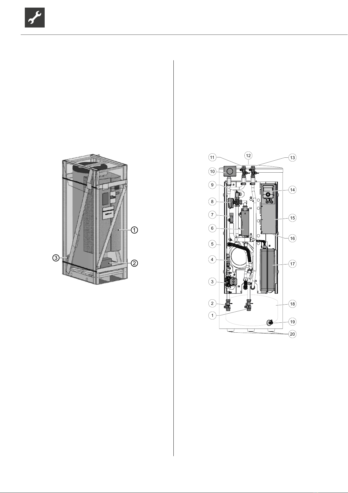
4.2 Components of the device ........................ 6
5 Storage, transport, installation................... 7
5.1 Storage...................................................... 7
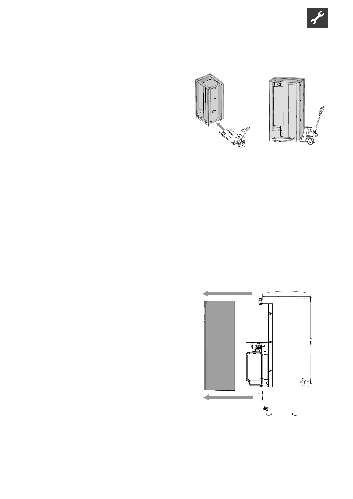
5.2 Unpacking and transport........................... 7
5.3 Installation................................................. 9
6 Installing the hydraulic connections ....... 10
6.1 Heating circuit ..........................................11
6.2 Expansion vessel .....................................11
6.3 Hydraulic connection for the
domestic hot water tank ...........................11
7 Electrical installation................................... 12
7.1 Connect the electrical cables.................. 12
7.2 Electrical connection............................... 12
8 Installing the control panel........................ 14
...................... 14
9.1 Heating water quality .............................. 14
domestic hot water charging circuit......... 15
the domestic hot water tank .................... 16
10 Insulate hydraulic connections ................ 16
............................................. 17
........ 17
13 Commissioning ............................................ 17
14 Faults.............................................................. 18
14.1 Unlock the safety temperature limiter ..... 18
15 Dismantling and Disposal......................... 18
15.1 Dismantling ............................................. 18
15.2 Disposal and Recycling........................... 18
................... 19
HSV… ............................................................. 19
HSDV… ............................................................ 20
Free pressing ...................................................... 21
....................................................... 21
..................................................... 21
HSV 12.1M3...................................................... 21
HSDV 12.1M3 ................................................... 21
Dimensioned drawings ..................................... 22
.................................................. 22
HS(D)V 12.1M3 ................................................. 23
Installation plans................................................. 24
.................................................. 24
HS(D)V 12.1M3 ................................................. 25
Terminal diagrams ............................................. 26
HSV… ............................................................. 26
HSDV… .......................................................... 28
Terminal diagram, mains connection
heat pump 1~230V
+ electric heating element 3~400V ......... 30
Terminal diagram, mains connection
heat pump 1~230V
+ electric heating element 1~230V ......... 31
Terminal diagram, mains connection
heat pump 3~400V
+ electric heating element 3~400V ......... 32
Circuit diagrams.................................................. 33
HSV… ............................................................. 33
HSDV… .......................................................... 37

3Subject to technical amendments without prior notice | 83059300iUK | ait-deutschland GmbH
1 About this operating manual
This operating manual is part of the device.
Before working on or with the device, read the op-
erating manual carefully and follow it for all activi-
ties at all times, especially the warnings and safe-
ty instructions.
Keep the operating manual to hand at the de-
vice and hand over to the new owner if the device
changes hands.
If you have any questions or anything is unclear,
ask the local partner of the manufacturer or the
factory's customer service.
Note and follow all reference documents.
1.1 Validity
This operating manual exclusively refers to the de-
( “Nameplate“,
page 7)
.
1.2 Reference documents
The following documents contain additional informa-
tion to this operating manual:
Planning & design manual, hydraulic integration
Operating manual of the heat pump
Operating manual of the heating and heat pump
controller
Brief description of the heat pump controller
Operating manual of the expansion board (acces-
sories)
Log book
1.3 Symbols and markings
Symbol Meaning
Safety-relevant information.
Warning of physical injuries.
DANGER Indicates imminent danger resulting
in severe injuries or death.
WARNING Indicates a potentially dangerous
situation, which can result in severe
injuries or death.
CAUTION Indicates a potentially dangerous
situation, which can result in
moderate or minor injuries.
IMPORTANT Indicates a potentially dangerous
situation, which can result in
property damage.
Symbols in the document
Symbol Meaning
Requirement for action
Procedural instructions:
Single step action prompt
1., 2., 3., … Procedural instructions:
Numbered step within a multi-step
action prompt. Keep to the given
order.
Additional information, e.g. a tip on
making work easier, information on
standards
Reference to further information
elsewhere in the operating manual
or in another document
Listing
Secure connections against twisting

4Subject to technical amendments without prior notice | 83059300iUK | ait-deutschland GmbH
1.4 Contact
Addresses for purchasing accessories, for service
cases or for answers to questions about the device
and this operating manual can be found on the internet
and are kept up-to-date:
www.ait-deutschland.eu
2 Safety
condition and only use it as intended, safely and aware
of the hazards, and follow this operating manual.
2.1 Intended use
The unit is designed for household use and is solely
intended for the following purposes:
Heating
Domestic hot water preparation
Proper use includes complying with the operating
conditions ( -
ply“, from page 19) and the operating manu-
al and noting and following the reference docu-
ments.
When using the local regulations note: laws,
standards, guidelines, directives.
All other uses of the device are not as intended.
2.2
The operating manuals supplied with the product are
intended for all users of the product.
The operation of the product via the heating and heat
pump control and work on the product which is intend-
groups of persons who are able to understand the ac-
tivities and the resulting consequences and can carry
out the necessary activities.
Children and adults who are not experienced in han-
dling the product and do not understand the neces-
sary activities and the resulting consequences must
be instructed and, if necessary, supervised by persons
experienced in handling the product and who are re-
sponsible for safety.
Children must not play with the product.
All procedural instructions in this operating manual is
the work on the device safety and correctly. Interfer-
-
ing injuries and damage to property.
Ensure that the personnel are familiar with the lo-
cal regulations, especially those on safe and haz-
ard-aware working.
Work on the refrigerating circuit may only be car-
only people permitted to work on the electrics and
electronics.
Other work on the system should only be carried
Heating engineers
Plumbers
During the warranty and guarantee period, service
work and repairs may only be carried out by personnel
authorised by the manufacturer.
2.3 Personal protective equipment
During transport and work on the unit, there is a risk of
cuts due to the sharp edges of the unit.
Wear cut-resistant protective gloves.
During transport and work on the unit, there is a risk of
foot injuries.
Wear safety shoes.
When working on liquid-conveying lines, there is a risk
of injury to the eyes due to leakage of liquids.
Wear safety goggles.

5Subject to technical amendments without prior notice | 83059300iUK | ait-deutschland GmbH
2.4 Residual risks
Electric shock
Components in the device are energised with
life-threatening voltage. Before working on the unit:
Disconnect the device from power supply.
Protect the device against being switched back
on again.
Existing earthing connections within housings or on
mounting plates must not be altered. If this should nev-
ertheless be necessary in the course of repair or as-
sembly work:
Restore earthing connections to their original con-
dition after completion of the work.
Injuries caused by high temperatures
Before working on the unit, let it cool down.
2.5 Avoid damage to property
Improper action
Requirements for minimum scale and corrosion dam-
age in hot water heating systems:
Proper planning, design and commissioning
Closed system with regard to corrosion
Integration of an adequately dimensioned pres-
sure maintaining device
Use of demineralised heating water (VE water) or
water corresponding to the VDI 2035 norm
Regular servicing and maintenance
If a system is not planned, designed, started up and
operated according to the given requirements, there is
a risk that the following damage and faults will occur:
Malfunctions and the failure of components, e.g.
pumps, valves
Internal and external leaks, e.g. from heat ex-
changers
Cross-section reduction and blockages in compo-
nents, e.g. heat exchanger, pipes, pumps
Material fatigue
Gas bubbles and gas cushion formation (cavita-
tion)
coatings, deposits, and associated noises, e.g.
Note and follow the information in this operating
manual for all work on and with the device.
water in the heating circuit
heat generator and the heating components depend
decisively on the quality of the heating water.
-
ter, calcium precipitates as scale. Lime scale deposits
form on the heat transfer surfaces of the heating. The
-
es, the heat exchangers will be damaged.
Fill the system with deionised heating water
(VE water) or with water corresponding to the VDI
2035 norm only (low-salt operation of the system).
3 Operation and care
NOTE
The device is operated via the control panel
of the heating and heat pump controller
( operating manual of the heating and
heat pump controller).
3.1 Energy and environmentally
conscious operation
The generally accepted requirements for energy con-
scious and environmentally conscious operation of a
heating system also apply to use of a heat pump. The
most important measures include:
No unnecessarily high domestic hot water tem-
perature (note and follow local regulations)
Do not open windows with just a gap or tilt open
(continuous ventilation), but instead open wide for
a short time (shock ventilation)
Always ensure that the controller settings are cor-
rect

6Subject to technical amendments without prior notice | 83059300iUK | ait-deutschland GmbH
3.2 Care
Wipe down the outside of the device only using a
damp cloth or cloth with mild cleaning product (wash-
ing up liquid, neutral cleaning product). Do not use any
harsh, abrasive, acid or chlorine-based cleaning prod-
ucts.
4 Scope of supply
Example of scope of supply arrangement
1 Compact device (domestic hot water tank and
2 Accompanying parts package: safety module,
pump ball valves, outdoor temperature sensor,
adjustable feet
3 Accompanying parts package: control panel for
the heating and heat pump controller
1. Inspect the delivery for outwardly visible signs of
damage.
2. Inspect the scope of supply for completeness.
Any defects or incorrect deliveries must be report-
ed immediately.
4.1 Accessories
The following accessories are available for the device
through the manufacturer's local partner:
Expansion circuit printed board with various addi-
tional functions
Room control panel for controlling the main func-
tions from the living room
Electrical connection kit EVS or EVS 8 (not for
dual units)
4.2 Components of the device
5
12
11
2
13
18
19
4
9
20
1
7
3
8
6
10
17
15
14
16
(with drain tap only in the case of
HS(D)V 9…)
*)
*)
3 Heating circuit recirculating pump (HUP)
(only with HSDV variants)
5 Domestic hot water tank
6 Electric heating element behind shielding
panel
8 Switchover valve domestic hot water
9 Vent valve
10 Heating circuit safety module (insulated)
*)
(return)
*)
12 Protection anode

7Subject to technical amendments without prior notice | 83059300iUK | ait-deutschland GmbH
(supply)
*)
14 Control panel
*)
15 Switch box
16 Sockets for the electrical connection kit EVS
or EVS 8
17 Expansion tank
20 Adjustable feet *)
*) to be mounted at the installation location
Nameplate
A nameplate is attached to the outside of the unit at
the factory.
The nameplate contains the following information at
the very top:
Model, item number
Serial number
The nameplate also contains an overview of the most
important technical data.
5 Storage, transport, installation
5.1 Storage
Store unit protected against:
Frost
Dust and dirt
5.2 Unpacking and transport
Notes on safe transport
The device is heavy (
supply“, from page 19). There is a risk of injuries or
damage to property if the device falls or overturns.
The hydraulic connections are not designed for me-
chanical loads.
Do not lift or transport the device by the hydraulic
connections.
Transport the device preferably with a pallet truck,
alternatively with a handcart or by carrying.
5.2.1 Transport with a pallet truck
Unpacking
1. -
age the device.
2. Dispose of the transport and packaging material
in an environmentally friendly way and in accord-
ance with local regulations.
If the device is to be carried, then it is recommended
that the wooden pallet is not removed yet.
5.2.2 Making transport easier
In order to make the transport simpler and easier, the
whole hydraulic system(including the controller with
switch box) can be unscrewed beforehand.
1.

8Subject to technical amendments without prior notice | 83059300iUK | ait-deutschland GmbH
2. Disconnect the domestic hot water temperature sen-
sor (TBW) inside the switch box and withdraw the
sensor cable out of its grommet in the switch box.
Opening and closing the switch box:
“Open the side cover of the electrical switch box”,
page 13
Terminals for the domestic hot water temperature
sensor:
„Terminal diagrams“, from page 26
3.
4x
4.
5.
IMPORTANT
cable of the domestic hot water temperature sensor
through its grommet in the support plate and place it
behind the support plate. Be careful not to damage
the cable.
6. Re-attach the hydraulics and hood after aligning
the unit.
“5.3 Installation”, page 9
5.2.3 Transport with handcart
IMPORTANT
Do not damage the hydraulic connections on the rear
of the unit, the hood on the hydraulics or the insula-
5.2.4 Carrying the unit
In order to make it easier to carry, a T-piece with two
outlet. It is recommended that the wooden pallet is on-
ly removed after carrying is complete.
Carry the unit to the installation site with 3 – 4 per-
sons.

9Subject to technical amendments without prior notice | 83059300iUK | ait-deutschland GmbH
5.3 Installation
Installation site
IMPORTANT
Only ever install the device inside buildings.
The installation area must be frost-free and dry. It must
„Installation plans“, from page 24 and „Dimen-
sioned drawings“, from page 22, for the respec-
tive model
1. Place the device on a stable and horizontal sur-
face, preferably decoupled from structure-borne
noise.
2. Tilt the device slowly and carefully to one side.
3. Secure the tilted device to ensure that it cannot tip
back to its initial position.
4. Fit the adjustable feet (①) to all 3 feet.
1
5. Tilt the device slowly and carefully back to its ini-
tial position.
6. Level out the 3 adjustable feet.
7. If the hydraulic system was dismantled for trans-
port reasons, then it must be screwed back into
place on the tank!
7.1.
IMPORTANT
When mounting the hydraulic system, insert the ca-
ble of the domestic hot water temperature sensor
through its grommet into the support plate. Take care
not to damage the cable.
7.2.
7.3.
7.4.
4x

10 Subject to technical amendments without prior notice | 83059300iUK | ait-deutschland GmbH
6 Installing the hydraulic
connections
IMPORTANT
Dirt and deposits in the (existing) hydraulic system
can cause damage to the heat pump.
Ensure that a sludge separator is installed in the
hydraulic system.
Rinse the hydraulic system thoroughly prior to es-
tablishing the hydraulic connection of the heat
pump.
IMPORTANT
Damage to the copper pipes due to unacceptable
loading!
Secure all connections against twisting.
Cross-sections and lengths of the pipes for the
heating circuit are adequately dimensioned. In do-
ing so, ensure that the connection pipework be-
tween the heat pump and hydraulic station are also
taken into account.
Freely pressing the recirculating pump produces
at least the minimum throughput required for the
device type ( “Free pressing”, page 21).
ceiling at a maximum distance of 20 cm from the
centre of the respective unit connection.
Insert the vent at the highest point of the heating
circuit.
Lift up the hood at the front of the hydraulic station
( “5.2.2 Making transport easier“, page 7).
8. temperature sensor (TBW) through its grommet
into the switch box and connect it.
Opening and closing the switch box:
“Open the side cover of the electrical switch box”,
page 13
Terminals for the domestic hot water temperature
sensor:
„Terminal diagrams“, from page 26
9. If no further hydraulic or electrical work is being
carried out for the time being, put the hood on the
hydraulics.
6x

11Subject to technical amendments without prior notice | 83059300iUK | ait-deutschland GmbH
6.1 Heating circuit
1.
the connections provided. Use seals from the ac-
cessory pack.
2. Lay the safety discharge of the safety valve into
the drain via a funnel waste trap according to the
relevant standards and guidelines.
It is essential that the safety discharge is connect-
ed.
Heating water inlet and outlet
1. Establish the hydraulic connection to the unit.
2. Establish the hydraulic connection to the heating
circuit.
Position of the connections: “Dimensioned draw-
ings”, page 22
6.2 Expansion vessel
The expansion vessel for the heating circuit is integrated.
Always inspect whether the size of the expansion ves-
sel is large enough for the system. If necessary, an ad-
ditional expansion vessel must be installed on site in
accordance with the relevant valid standards.
NOTE
The admission pressure of the expansion
vessel must be adjusted to the system (ap-
-
sure) in accordance with calculation accord-
ing to the relevant standards (EN 12828).
6.3 Hydraulic connection for the
domestic hot water tank
Connect the domestic hot water tank according to DIN
1988 and DIN 4753 Part 1 (or the standards and direc-
tives applicable locally).
Position of the connections: “Dimensioned draw-
ings“, page 22
The working overpressure cited on the name plate
must not be exceeded. Install a pressure reducer if re-
quired.
The sensor for the domestic hot water preparation is
already connected in the switch box.
IMPORTANT
The electrical conductivity of the domestic hot water
-
able water quality limits.

12 Subject to technical amendments without prior notice | 83059300iUK | ait-deutschland GmbH
7 Electrical installation
7.1 Connect the electrical cables
IMPORTANT
Irreparable damage to the compressor due to wrong
the compressor load infeed.
Basic information on the electrical connection
company may apply to electrical connections
Fit the power supply for the heat pump with an
all-pole circuit breaker with at least 3 mm contact
spacing (per IEC 60947-2)
Note the level of the tripping current („Technical
Comply with the electromagnetic compatibility
regulations (EMC regulations)
Lay unshielded power supply cables and shielded
Maximum line length: 30m
Cable extension details see operating manual of
the heat pump
Establish the electrical connections between
the heat pump and the hydraulic station
Operating manual of the heat pump
NOTE.
For dual output-controlled heat pumps, the
lines (8 m) are already connected to the heat
pump.
7.2 Electrical connection
The electrical connection is established via the switch
box.
The hydraulic station is connected on site to the
sub-distribution according to the following scheme:
1 Heat pump
2 Load Compressor
3 Bus (shielded)
4 Control voltage (for dual heat pump only)
5 Hydraulic station
6 Elektric heating element load line
7 Control voltage
8 Load Compressor
9 Sub-distribution
1. Feed the control and sensor cables, the Bus and
load cable from the heat pump, the cable for the
EVU blocking time as well as the cables of exter-
nal loads through the grommet on the rear (①) of
the device into the interior of the device.
1
1
2
2. Feed the cables through the cable duct (②) to the
switch box.

13Subject to technical amendments without prior notice | 83059300iUK | ait-deutschland GmbH
9. Route plug-in connections for the control panel
out of the openings (⑦) in the front cover of the
electrical switch box.
6
7
N
NOTE
The control panel for the heating and heat
pump controller can be connected to a com-
puter or network using a suitable network ca-
ble, enabling the heating and heat pump con-
troller to be controlled remotely from there.
If such a connection is desired, route a
shielded network cable (Ⓝ, category 6, with
RJ45 connector) through the electrical switch
box and plug it to the corresponding socket
of the control panel.
“Connections on the control panel”, page 14
NOTE
In devices with integrated electric heat-
ing element, the electric heating element
is connected for 9 kW (6 kW) in the factory.
At contactor Q, it is possible to select 6 kW
(4 kW) = 2 phase operation. Disconnect
-
The values in brackets are for the 6 kW heat-
ing element. Disconnected cables must be
furnished with screw terminals. Only the
phases cited above may be disconnected
(safety temperature limiter).
Q
10. Close the electrical switch box by re-attaching the
side cover.
3. Insert the wired plugs of the heat pump load cable
(③) and the bus cable (④) into the corresponding
socket at the bottom of the electrical switch box.
34
4. Strip of all other cables before feeding them into
the switch box (stripping length of each of the indi-
vidual wires: 6 mm).
5. Open the side cover (⑤) of the electrical switch
box.
5
5
6. Feed the cables into the cable ducts of the switch
box.
7. Carry out electrical connections in accordance
with the terminal diagram.
„Terminal diagram“ for the respective model, from
page 26
8. Insert all cables introduced into the switch box in-
to the cable ducts in the switch box, route them
through the strain reliefs (⑥) and screw them into
the strain reliefs.

14 Subject to technical amendments without prior notice | 83059300iUK | ait-deutschland GmbH
8 Installing the control panel
1.
4x
2.
4x
3. Make cable connections on the bottom of the con-
trol panel.
1 2 43
1 RS485 for connecting the room control unit
RBE (accessory)
2 RJ45 for network cable connection
3 RS485 LIN bus cable connection to the
control board
4 RJ45 connection Modbus cable to Modbus
distributor.
9
9.1 Heating water quality
NOTE
For detailed information refer, among other
things, to the VDI Guidelines 2035 “Ver-
meidung von Schäden in Warmwasserhei-
zanlagen” (preventing damage in hot water
heating systems)
Required pH value: 8.2 … 10;
for aluminium materials:
pH value: 8.2 … 8.5
Fill the system with deionised heating water
(VE water) or with water corresponding to the VDI
2035 norm only (low-salt operation of the system).
Advantages of low-salt operation:
Low corrosion-promoting properties
No formation of mineral scale
Ideal for closed heating circuits
the system
If the required water quality is not achieved, con-
sult a company specialising in the treatment of
heating water.
Keep a system log for hot water heating systems
in which relevant planning data is entered (VDI
2035).

15Subject to technical amendments without prior notice | 83059300iUK | ait-deutschland GmbH
9.2
domestic hot water charging
circuit
Outlet pipe of the safety valve is connected.
Ensure that the set pressure of the safety valve is
not exceeded.
NOTE
The venting programme on the controller can
-
ing process. It is possible to control individual
recirculating pumps and also the switchover
valve via the venting programme. As a result,
it is not necessary to remove the valve motor.
1. Vent the system at the highest point.
2. Open the vent valve (①) on the 3-way switching
valve.
1
3. (②) on the back of the valve mo-
tor (③) on the switching valve (④) upwards.
2
3
4. Carefully pull the valve motor (③)
3-way switching valve (④).
43
5. Turn the spindle of the 3-way switching valve so
that the rounded side of the spindle points in the
direction of marking A of the connections of the
3-way switching valve.
A
B
6. Flush the domestic hot water charging circuit for
approx. 1 minute.
7. Turn the spindle so that the rounded side of the
spindle points in the direction of marking B of the
connections of the 3-way switching valve.
8. Flush heating circuit thoroughly, until no more air
is discharged.
9. Position the valve motor (③) on the 3-way switch-
ing valve (④).
43

16 Subject to technical amendments without prior notice | 83059300iUK | ait-deutschland GmbH
10. Insert the U-clip (②) into the base of the valve mo-
tor (③).
2
3
11. Ensure that the U-clip has latched into position
correctly:
Valve motor sits securely on the 3-way switch-
ing valve.
Both prongs of the U-clip sit on the lug.
The tips of the U-clip are not visible more than
approx. 2 mm.
12. Close the vent valve (①) on the 3-way switching
valve.
1
9.3
the domestic hot water tank
IMPORTANT
tank, the outlet pipe of the safety valve must be con-
nected. The set pressure of the safety valve must not
be exceeded.
1. Open the domestic cold water supply valve on the
domestic hot water tank.
2. Open the domestic hot water valves at the tapping
points.
3. Flush the domestic hot water tank until no more air
discharges from the valves at the tapping points.
4. Close the domestic hot water valves at the tap-
ping points.
10 Insulate hydraulic connections
Insulate hydraulic lines in accordance with local regu-
lations.
1.
2. Perform a pressure test and check for leaks.
3. Insulate external piping on site.
4.

17Subject to technical amendments without prior notice | 83059300iUK | ait-deutschland GmbH
11
2
1
1 O
2 Adjusting knob
Operating manual of the heat pump
12
heat meter
(only with HSDV variants)
①) integrat-
ed in HSDV units is used to measure the heat quan-
tity generated by the heating system and made avail-
able for domestic hot water preparation and building
heating.
1
The measuring ranges are set in the heating and heat
pump controller. Measured values can be read out on
the control panel display.
Operating manual of of the heating and heat
pump controller
13 Commissioning
Water supply to the domestic hot water tank is
open
NOTE
If the heat pump is switched on whilst the tank
is empty, the control panel indicates a fault.
Operating manual of the heating and heat pump
controller
Operating manual of the heat pump

18 Subject to technical amendments without prior notice | 83059300iUK | ait-deutschland GmbH
14 Faults
Read out the cause of the fault via the diagnostics
programme of the heating and heat pump control-
ler.
Contact the local partner of the manufacturer or
the factory's customer service. Have the fault
message and device number to hand.
14.1 Unlock the safety temperature
limiter
A safety temperature limiter is installed in the electric
heating element. If the heat pump fails or there is air in
the system:
Check whether the reset
button
(①) in the centre
of the safety temperature limiter
(②,
located
underneath the cover) has tripped.
If the reset button
(①)
has tripped, press it again
using a small screwdriver
(③)
.
2
1
3
If the safety temperature limiter trips again, con-
tact the local partner of the manufacturer or the
factory’s customer service.
15 Dismantling and Disposal
15.1 Dismantling
Separate components by their materials.
15.2 Disposal and Recycling
Recycle or ensure proper disposal of device com-
ponents and packaging materials in accordance
with local regulations.
1.
on the processor circuit board of the heating and
heat pump controller.
2.
local regulations.

19Subject to technical amendments without prior notice | 83059300iUK | ait-deutschland GmbH
Accessories for heat pump type HSV 9M1/3 HSV 12.1M3
Air/water 8 kW output-controlled | Air/water 12 kW output-controlled • yes – no • | – • | •
Air/water dual output-controlled • yes – no – | – – | –
Air/water 7 kW to 8 kW output-controlled | Air/water 10 kW to 18 k
Outdoor installation • yes – no – | – – | –
Air/water 9 kW to 14 kW RX Outdoor installation • yes – no – | – – | –
Air/water dual Outdoor installation • yes – no – | – – | –
Air/water dual RX Outdoor installation • yes – no – | – – | –
Installation location
Room temperature min. | max. °C 5 | 35 5 | 35
Relative humidity %60 60
Sound
Sound pressure level at 1 m distance inside dB(A) 36 36
Sound power level inside dB(A) 44 44
Heating circuit
Flow rate: minimum | maximum (see heat pump for pipe dimensioning) l/h | l/h 600 | 1200 600 | 1900
Free pressing | Pressure loss | Flow rate bar | bar | l/h 0,63 | – | 1200 0,55 | – | 1900
Max. allowable operating pressure bar 3 3
Circulation pump control range min. | max. l/h 600 ı 1200 600 ı 1900
General unit data
Total weight kg 150 161
Weight of individual components kg | kg | kg – | – | – – | – | –
Domestic hot water tank
Net volume l180 279
Magnesium sacrificial anode Impressed current | Magnesium • yes – no – | • – | •
Domestic hot water temperature, heating pump mode | Electric heating element up to °C | up to °C 55 | 65 55 | 65
Mixed water quantity according to ErP: 2009/125/EC (at 40 °C, draw-off of 10 l/min) l230 365
Standing loss according to ErP: 2009/125/EC (at 65 °C) W55 66
Maximum pressure | Operating pressure bar | bar 6 | 10 | 13 6 | 10 | 13
Electrics
Voltage code | all-pole fuse protection for heat pump *)**) 1 phase … | A 1~N/PE/230V/50Hz | B16 1~N/PE/230V/50Hz | B16
Voltage code | all-pole fuse protection for heat pump *)**) 3 phases … | A – | – 3~N/PE/400V/50Hz | B16
Voltage code | Control voltage fuse protection **) … | A 1~N/PE/230V/50Hz | B10 1~N/PE/230V/50Hz | B10
Voltage code | Electric heating element fuse protection **) 1 phase … | A 1~N/PE/230V/50Hz | B32 – | –
Voltage code | Electric heating element fuse protection **) 3 phases … | A 3~N/PE/400V/50Hz | B10 3~N/PE/400V/50Hz | B16
Degree of protection IP 20 20
Residual current circuit breaker if required type B B
Electric heating element output 3 | 2 | 1 phase kW | kW | kW 6 | 4 | 2 9 | 6 | 3
Circulation pump power consumption, heating circuit min. | max. W4 | 75 4 | 75
Other unit information
Safety valve Heating circuit | Response pressure included in scope of supply: • yes – no | bar • | 3 • | 3
Buffer tank | Volume included in scope of supply: • yes – no | l • | 62 • | 83
Diaphragm expansion vessel Heating circuit | Volume | Prepressure incl. in scope of supply: • yes – no | l | bar • | 12 | 1,5 • | 12 | 1,0
Overflow valve | Changeover valve, heating -Domestic hot water integrated: • yes – no • | • • | •
Vibration decoupling, Heating circuit | Heat source included in scope of supply or integrated: • yes – no – –
Controller | Heat quantity recording | Extension board included in scope of supply or integrated: • yes – no • | • | – • | • | –
813320b 813326a
*) compressor only, **) note local regulations
HSV…

20 Subject to technical amendments without prior notice | 83059300iUK | ait-deutschland GmbH
Accessories for heat pump type HSDV 9M1/3 HSDV 12.1M3
Air/water 8 kW output-controlled | Air/water 12 kW output-controlled • yes – no – | – – | –
Air/water dual output-controlled • yes – no • •
Air/water 7 kW to 8 kW output-controlled | Air/water 10 kW to 18 k
Outdoor installation • yes – no – | – – | –
Air/water 9 kW to 14 kW RX Outdoor installation • yes – no – –
Air/water dual Outdoor installation • yes – no – –
Air/water dual RX Outdoor installation • yes – no – –
Installation location
Room temperature min. | max. °C 5 | 35 5 | 35
Relative humidity %60 60
Sound
Sound pressure level at 1 m distance inside dB(A) 33 33
Sound power level inside dB(A) 46 46
Heating circuit
Flow rate: minimum | maximum (see heat pump for pipe dimensioning) l/h | l/h 700 | 1600 700 | 1600
Free pressing | Pressure loss | Flow rate bar | bar | l/h 0,65 | – | 1150 0,81 | – | 1150
Max. allowable operating pressure bar 3 3
Circulation pump control range min. | max. l/h 600 ı 1200 600 ı 1900
General unit data
Total weight kg 150 161
Weight of individual components kg | kg | kg – | – | – – | – | –
Domestic hot water tank
Net volume l180 279
Magnesium sacrificial anode Impressed current | Magnesium • yes – no – | • – | •
Domestic hot water temperature, heating pump mode | Electric heating element up to °C | up to °C 60 | 65 60 | 65
Mixed water quantity according to ErP: 2009/125/EC (at 40 °C, draw-off of 10 l/min) l230 365
Standing loss according to ErP: 2009/125/EC (at 65 °C) W55 66
Maximum pressure | Operating pressure bar | bar 6 | 10 | 13 6 | 10 | 13
Electrics
Voltage code | all-pole fuse protection for heat pump *)**) 1 phase … | A 1~N/PE/230V/50Hz | B16 1~N/PE/230V/50Hz | B16
Voltage code | all-pole fuse protection for heat pump *)**) 3 phases … | A – | – – | –
Voltage code | Control voltage fuse protection **) … | A 1~N/PE/230V/50Hz | B16 1~N/PE/230V/50Hz | B16
Voltage code | Electric heating element fuse protection **) 1 phase … | A 1~N/PE/230V/50Hz | B25 – | –
Voltage code | Electric heating element fuse protection **) 3 phases … | A 3~N/PE/400V/50Hz | B10 3~N/PE/400V/50Hz | B16
Degree of protection IP 20 20
Residual current circuit breaker if required type B B
Electric heating element output 3 | 2 | 1 phase kW | kW | kW 6 | 4 | 2 9 | 6 | 3
Circulation pump power consumption, heating circuit min. | max. W4 | 75 4 | 75
Other unit information
Safety valve Heating circuit | Response pressure included in scope of supply: • yes – no | bar • | 3 • | 3
Buffer tank | Volume included in scope of supply: • yes – no | l • | 62 • | 83
Diaphragm expansion vessel Heating circuit | Volume | Prepressure incl. in scope of supply: • yes – no | l | bar • | 12 | 1,5 • | 12 | 1,0
Overflow valve | Changeover valve, heating -Domestic hot water integrated: • yes – no • | • • | •
Vibration decoupling, Heating circuit | Heat source included in scope of supply or integrated: • yes – no – –
Controller | Heat quantity recording | Extension board included in scope of supply or integrated: • yes – no • | • | – • | • | –
813324a 813327b
*) compressor only, **) note local regulations
HSDV…
This manual suits for next models
5
Table of contents
Other AIT Heat Pump Accessories manuals