AIT MFS 600S User manual

UK
83017400dUK
Accessories for
heat pumps
Operating Manual
Multi-functional domestic hot water storage tank
MFS 600S, MFS 830S, MFS 1000 S

2Subject to change without notice | 83017400dUK | ait-deutschland GmbH
1 Please read first
This operating manual provides important information
on the handling of the unit. It is an integral part of the
product and must be stored so that it is accessible
in the immediate vicinity of the unit. It must remain
available throughout the entire service life of the unit.
It must be handed over to subsequent owners or users
of the unit.
Read the operating manual before working on or
operating the unit. This applies in particular to the
chapter on safety. Always follow all instructions
completely and without restrictions.
It is possible that this operating manual may contain
instructions that seem incomprehensible or unclear. In
the event of any questions or if any details are unclear,
contact the factory customer service department or
the manufacturer’s local partner.
Since this operating manual was written for several
different models of the unit, always comply with the
parameters for the respective model.
This operating manual is intended only for persons
assigned to work on or operate the unit. Treat all
constituent parts confidentially. The information
contained herein is protected by copyright. No part of
this manual may be reproduced, transmitted, copied,
stored in electronic data systems or translated into
another language, either wholly or in part, without the
express written permission of the manufacturer.
2 Symbols
The following symbols are used in the operating
manual. They have the following meaning:
Information for operators.
technicians.
DANGER
Indicates a direct impending danger
resulting in severe injuries or death.
WARNING
Indicates a potentially dangerous situation
that could result in serious injuries or
death.
CAUTION
Indicates a potentially dangerous situation
that could result in medium or slight
injuries.
IMPORTANT
Indicates a potentially dangerous situation,
which could result in property damage.
NOTE
Emphasised information.
1., 2., 3., … Numbered step within a multi-step
instruction for action.
Adhere to the given sequence.
Single-step instruction for action
List
Reference to further information elsewhere
in the operating manual or in another docu-
ment.

3
Subject to change without notice | 83017400dUK | ait-deutschland GmbH
Contents
1 Please read first ............................................ 2
2 Symbols........................................................... 2
3 Intended use................................................... 4
4 Disclaimer ....................................................... 4
5 Safety ............................................................... 4
5.1 Personal protective equipment ................. 5
6 Contact............................................................. 5
7 Warranty / Guarantee .................................. 5
8 Disposal........................................................... 5
9 Maintenance of the unit............................... 5
10 Scope of delivery .......................................... 5
11 Transport, Installation, Assembly.............. 6
11.1 Transport to installation location ............... 6
11.2 Installation................................................. 7
11.3 Circulation kit installation .......................... 8
11.4 Insulate the circulation connection............ 9
11.5 Hydraulic connections............................... 9
11.6 Sensor installation................................... 10
Technical Data .....................................................11
Dimensional drawings....................................... 12
MFS 600 S........................................................ 12
MFS 830 S........................................................ 13
MFS 1000 S ...................................................... 14
Installation plan for all storage tanks................ 15
Hydraulic connections....................................... 16
Variant 1 ........................................................... 16
Variant 2 ........................................................... 17
Legend hydraulic diagram ................................ 18

4Subject to change without notice | 83017400dUK | ait-deutschland GmbH
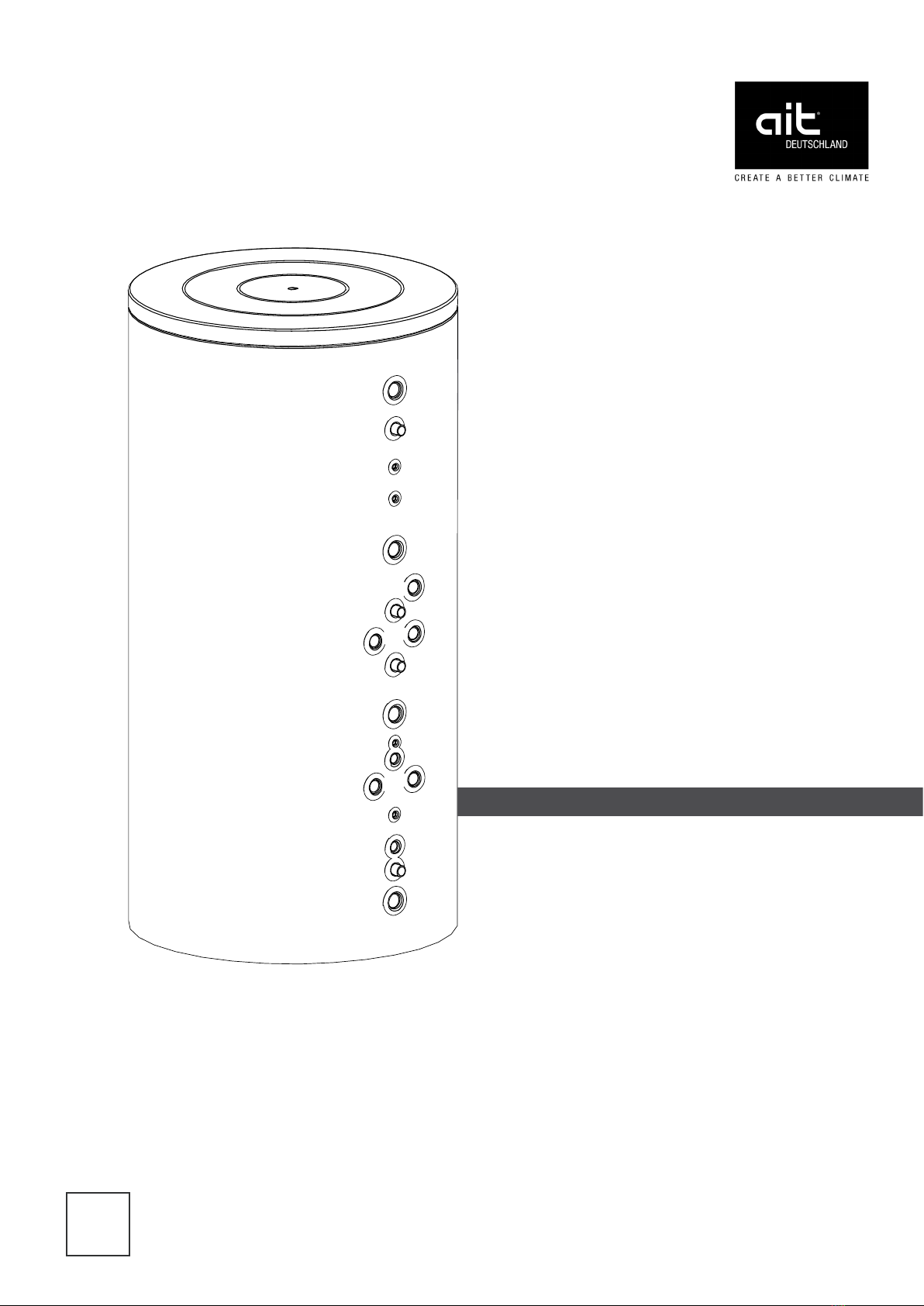
3 Intended use
The multi-functional storage tank may be used only for
the intended purpose.
This is as a stratified storage tank used in conjunction
with heat pumps.
with buffer area for heating system water
domestic water heating using the continuous
flow principle
for air/water heat pumps
brine/water heat pumps
water/water heat pumps
Can be connected to solar systems and solid fuel
boilers.
The unit may be operated only within its technical
parameters.
“Technical data” overview and “Technical da-
ta / Scope of delivery” overview of the operating
manual for the heat pump to which the multi-func-
tional storage tank is connected.
If local regulations apply, observe: laws, stand-
ards and directives.
4 Disclaimer
The manufacturer is not liable for losses resulting from
any use of the unit which is not its intended use.
The manufacturer’s liability also expires:
if work is carried out on the unit and its compo-
nents contrary to the instructions in this oper-
ating manual.
if work is improperly carried out on the unit and
its components.
if work is carried out on the unit which is not
described in this operating manual, and this
work has not been explicitly approved by the
manufacturer in writing.
if the unit or components in the unit have been
altered, modified or removed without the ex-
plicit written consent of the manufacturer.
5 Safety
The unit is safe to operate when used for its intended
purpose. The construction and design of the unit
conform to current state-of-the-art standards, all
relevant DIN/VDE regulations and all relevant safety
regulations.
The operating manuals supplied with the product are
intended for all users of the product.
The operation of the product via the heating and he-
at pump control and work on the product which is in-
tended for end customers / operators is suitable for all
age groups of persons who are able to understand the
activities and the resulting consequences and can car-
ry out the necessary activities.
Children and adults who are not experienced in hand-
ling the product and do not understand the necessa-
ry activities and the resulting consequences must be
instructed and, if necessary, supervised by persons
experienced in handling the product and who are re-
sponsible for safety.
Children must not play with the product.
The product may only be opened by qualified personnel.
All instructional information in this operating manual is
solely directed at qualified, skilled personnel.
Only qualified, skilled personnel is able to carry out
the work on the unit safety and correctly. Interference
by unqualified personnel can cause life-threatening
injuries and damage to property.
Ensure that the personnel is familiar with the local
regulations, especially those on safe and hazard-
aware working.
Only allow qualified personnel with “electrical”
training to carry out work on the electrics and
electronics.
Only allow qualified, skilled personnel to do any
other work on the system, e.g.
Heating installer
Plumbing installer
Refrigeration system installer (maintenance
work)
Every person who carries out work on the unit must
comply with the applicable accident prevention and
safety regulations. This applies in particular to the
wearing of personal protective clothing.
During the warranty and guarantee period, servicing
and repair work may only be carried out by personnel
authorised by the manufacturer.

5
Subject to change without notice | 83017400dUK | ait-deutschland GmbH
5.1 Personal protective equipment
There is a risk of cutting your hands on sharp edges
of the unit.
Wear cut-resistant protective gloves during trans-
port.
6 Contact
Addresses for purchasing accessories, for servicing
or for answers to questions about the unit and this
operating manual can be found on the internet and are
kept up-to-date.
“Contact” in the heat pump operating manual
7 Warranty / Guarantee
For warranty and guarantee conditions, please refer to
the purchase documents.
NOTE
Please contact your dealer about all matters
concerning warranties and guarantees.
8 Disposal
When decommissioning the unit, always comply with
applicable laws, directives and standards concerning
recovery, recycling and disposal.
9 Maintenance of the unit
The components of the heating circuit and the heat
source (valves, expansion vessels, circulating pumps,
filters, dirt traps) should be inspected as well as
cleaned as needed - at the very least annually - by a
qualified heating or cooling system technician.
Check the safety valve (provided by customer) for the
hot water tank at regular intervals.
It is a good idea to have a maintenance contract with a
heating installation company. The company will carry
out the required maintenance at regular intervals.
10 Scope of delivery
Multi-functional domestic hot water storage tank
2 insulation shells, Sky jacket, rosettes for con-
nections, circulation connection kit
In extra box:
Circulation connection kit and insulation, 2 hot
gas sensors, 4 cable ties
1. Check the delivery for outwardly visible signs of
damage.
2. Check to make sure that the delivery is complete.
Report defects or incorrect deliveries immediately.
Accessories
IMPORTANT
Use only original accessories from the manu-
facturer of the unit.
Select heating elements, between 4.5 to 9 kW
depending on the specific system and order as
additional items.
Type MFS 600 S MFS 830 S MFS 1000 S
EHZI 45
EHZ 60
EHZ 75
EHZ 90
:suitable combination, n.g. :not suitable
For details of the quantity and positioning of the
heating element sockets, refer to the dimensioned
drawing of the respective tank.

6Subject to change without notice | 83017400dUK | ait-deutschland GmbH
11 Transport, Installation,
Assembly
The following applies to all work to be done:
NOTE
Always comply with the applicable local ac-
cident prevention regulations, statutory regu-
lations, ordinances, guidelines and directives.
WARNING
The storage tank may only be installed and
assembled by qualified technicians!
NOTE
It must be installed in a frost-free room with
short pipe lengths to the load. Please also
ensure that it is installed on a dry, firm sur-
face able to safely support its weight.
“Technical data, weight” overview
11.1 Transport to installation location
To avoid damage during transport, you should
transport the storage tank (secured on the wooden
pallet) to its final installation location using a lifting
truck.
If it is not possible to transport the unit to the final
installation location using a lifting truck, you can also
transport the unit using a hand truck.
WARNING
Several people are required to transport
the unit. Do not underestimate the weight
of the tank.
“Technical data, weight” overview.
CAUTION
Wear safety gloves.
WARNING
The unit can tip over when being removed
from the wooden pallet and during
transport with a hand truck or lift truck.
This can result in personal injuries and
damage.
Take suitable precautions, which pre-
vent the tipping hazard.
Proceed as follows if transport with a lifting truck is not
possible:
Remove packaging and insulating material. Remove
storage tank from the wooden pallet and bring it to the
installation location.
Dispose of the transport and packaging materials
properly and under ecological aspects.
Fastening on the wooden pallet
NOTE
The multi-functional domestic hot water stor-
age tank is delivered with full insulation. If
necessary, the insulation (Sky jacket and the
4 insulation shells) can be removed to trans-
port the tank into the basement.
IMPORTANT
All parts of the insulation must be carefully
removed and put aside so that they are not
damaged!
1. Remove the protective transport sheeting.
2. Remove the grommets from the connections.

7
Subject to change without notice | 83017400dUK | ait-deutschland GmbH
3. Lift off the tank cover.
4. Undo the Sky jacket zip and remove the jacket.
5. Remove both insulation shells and put them in a
safe place.
NOTE
Please note that all components must be re-
assembled in the reverse order!
WARNING
Make sure you secure the tank against
slipping during transport. Always secure
the tank on the hand truck with a ratchet
strap!
11.2 Installation
NOTE
Ensure that the foam insulation is still in the
bottom of the storage tank.
WARNING
The storage tank must always be tilted by
at least 2 people to prevent the risk of it
tipping over. Do not tilt the storage tank by
more than 20° during this step. Hands and
fingers can be crushed when the tank is
righted!
Do not grip the bottom of the tank!
Wear protective gloves!
1. Before you re-attach the insulation half-shells,
check whether a) the grommets are placed over
the pipe sockets and b) the soft foam sleeve is po-
sitioned over the top connection.
a) Grommets
b) Sleeve
2. Re-attach the insulation half-shells to the storage
tank.

8Subject to change without notice | 83017400dUK | ait-deutschland GmbH
3. Use adhesive tape to fix the insulation half-shells
at the top, bottom and in the middle part of the
tank.
4. Place the Sky jacket around the storage tank so
that the punched out holes fit over the sockets.
Then close the zip.
IMPORTANT
The zip must be closed by two people to re-
lieve the strain!
5. Replace the tank cover and push the grommets
over the corresponding pipe connections.
11.3 Circulation kit installation
NOTE
The connection between the top and bot-
tom heat exchanger must always be installed,
even if there is no circulation pipe!
1. Seal the two threads (1 and 2).
2. Screw the tee onto thread 1 and move into the
correct position (connection part facing down-
wards).
3. Seal the thread of the flexible corrugated pipe and
screw into the tee.

9
Subject to change without notice | 83017400dUK | ait-deutschland GmbH
4. Screw the 90° elbow onto thread 2 and move in-
to the correct position (elbow must face upwards).
5. Stretch the flexible corrugated pipe and insert the
seal between the elbow and the flexible corrugated
pipe.
6. Use the union nut to screw together the flexible
corrugated pipe and the elbow.
IMPORTANT
Tighten the union nut carefully to prevent
damage to the seal!
11.4 Insulate the circulation connection
NOTE
The circulation connection is installed outside
the shell insulation over the Sky jacket and is
then insulated.
1. Push the 110 mm long insulation hose (with pipe cut-
out) over the thread of the circulation connection.
2. Insulate the remaining piping of the circulation
connection with 220 mm long insulation hose (1).
Then fix the insulation hoses in 4 places using the
cable ties (2).
11.5 Hydraulic connections
Note and follow all relevant regulations, standards,
guidelines and directives when integrating the multi-
functional storage tank in the drinking water and heating
network.
Note and follow the relevant DVGW regulations and
recommendations and the regulations of the water
supply company when connecting to the drinking
water.
Integrate the multi-functional storage tank in the
heating system and domestic hot water circuit as
shown in the hydraulic diagram.
Hydraulic connection

10 Subject to change without notice | 83017400dUK | ait-deutschland GmbH
Do not exceed the operating pressures specified on
the rating plate and in the technical data. Install a
pressure reducer, if necessary.
IMPORTANT
The electrical conductivity of the domestic
hot water must be > 100 µS/cm and lie within
the required drinking water quality. The sul-
phate and chlorine content must not exceed
300 mg/l in total!
We recommend installing a suitable expansion vessel
(not included in delivery) in the hot water circuit. This
equalises pressure fluctuations or water shocks in the
cold water network and prevents unnecessary loss of
water.
Use a safely valve according to the respective relevant
standards, guidelines and directives and according
to the maximum allowable operating pressures of the
storage tank and components.
The safety drain of the safety valve must lead into
the drain via a funnel siphon in accordance with the
applicable standards and regulations!
Domestic hot water connection diagram to DIN 1988
1 Shut-off valve 2 Pressure reducing valve
3 Check valve 4 Pressure gauge and test valve
5 Safety valve 6 Emptying valve
7 Circulation pump 8 Vent valve
NOTE
This diagram does not take into account any
scalding protection!
Hydraulic connections
11.6 Sensor installation
Always use the sensor springs included in the scope
of delivery when installing the sensors (domestic hot
water sensor and return temperature sensor).
1. Position the sensor on the outside of the sensor
spring.
2
1 Sensor spring
2 Sensor
3 Sensor pocket (is already installed in the tank)
2. Push the sensor and sensor spring together into
the respective sensor pocket.
3. Push in the sensor up to the end of the sensor
pocket.
For position of the sensor pocket, see dimen-
sioned drawing
NOTE
Always install the sensor springs, to ensure
optimum temperature transfer! Take care not
to damage the insulation of the sensor cable!
NOTE
Refer to the instruction manual for the heat-
ing and heat pump regulator for the regula-
tor settings required for parallel tank. Refer to
the terminal diagram of the respective heat
pump type for details of the circulating pump
connections and, if installed, the changeover
valve!
Sensor connection as shown in the “terminal dia-
gram of the respective heat pump type”.

11
Subject to change without notice | 83017400dUK | ait-deutschland GmbH
MFS 600S MFS 830S MFS 1000S
• yes – no • • •
… – – –
W111 124 135
l552 826 903
°C 7 | 95 7 | 95 7 | 95
m³/h 5 5 5
…DIN 4753 DIN 4753 DIN 4753
• yes – no – – –
l504 769 830
bar 3 3 3
bar 4,5 4,5 4,5
°C – | 95 – | 95 – | 95
kW – – –
l 8 11 17
bar | l/h - | - - | - - | -
bar 10 10 10
bar 15 15 15
°C | 95 | 95 | 95
l40 46 56
bar | l/h - | - - | - - | -
bar 6 6 6
bar 12 12 12
°C – | 95 – | 95 – | 95
…1.4404 (V4A) 1.4404 (V4A) 1.4404 (V4A)
°C 55 55 55
m³/h 3 3 3
l200 210 210
l170 180 180
l220 240 240
l200 220 220
°C 7 | 35 7 | 35 7 | 35
%65 65 65
…SVGW / SEV SVGW / SEV SVGW / SEV
• yes – no • | – • | – • | –
mm 72,5 95 95
• yes – no • | – • | – • | –
• yes – no – | • – | • – | •
813605 813606 813607
Operating temperature minimum | maximum
Tank name
Multi-functional domestic hot water tank
Energy efficiency class according to ErP
Standing loss according to ErP (at 65°C)
Total tank volume according to ErP
Pressure loss | flow rate
Maximum allowable heating water flow rate
Corrosion protection according to
Enamelled surface
Heating water reservoir
Capacity
Max. operating pressure
Test pressure
Operating temperature minimum | maximum
Maximum heating output of the heat pump at heat source max.
Solar heat exchanger
Capacity
at heat pump flow temperature
Max. operating pressure
Test pressure
Operating temperature minimum | maximum
Domestic hot water heat exchanger
Capacity
Pressure loss | flow rate
Max. operating pressure
Test pressure
Operating temperature minimum | maximum
Material
Available quantity of domestic hot water
Material: Rigid foam | soft foam
Heat pump flow on charging
10 l/min drawn off at 45°C
20 l/min drawn off at 45°C
10 l/min drawn off at 38°C
20 l/min drawn off at 38°C
Installation location
Room temperature minimum | maximum
Relative humidity maximum (non-condensing)
General unit data
Tests
Insulation
Insulation thickness
as per DIN 4753
Sheet metal jacket ı Foil jacket
*) for further details see dimensional drawing | Manufacturer: ait deutschland GmbH | Index: a
Technical Data

12 Subject to change without notice | 83017400dUK | ait-deutschland GmbH
150
800
650
0
160
250
340
420
400
525
580
765
850
910
1005
1480
1250
1587
1740
1930
465
680
1 2
6
4
3
7
5
9
11
13
12
14
15
16
17
18
1" IG
Zirkulationsanschluss
(im Lieferumfang)
8
10
8
7
6
5
4
3
2
1
www.alpha-innotec.de
D - 95359 Kasendorf
Industriestraße 3
Alpha-InnoTec GmbH
Schutzvermerk nach DIN 34 beachten
1
1
Ers. d.
Ers. f.
A
B
C
D
E
F
F
E
D
C
B
A
4
3
2
1
Benennung
Maßbild
MFS 600S
819328
-
Zust.
Änderungstext
PEP 033/2009
Datum
3.2.2010
RA
Von
Blatt
von
Werkstoff
Gewicht
Maßstab
1:25
1:5
Det. Maßstab
Datum
Name
Erstellt
Gepr.
Norm.
19.1.2010
Aepfelbach
3.2.2010
Aepfelbach
toleranz
Allgemein-
DIN ISO 2768 -c
Oberflächen
ArtikelNr.
Net weight incl. insulation: 140 kg
Tilting dimension without insulation: 1900
Keys: UK819328 Domestic hot water exchanger: 7.5 m²
All dimensions in mm. Solar heat exchanger: 1.5 m²
1Ventilation
2 Flow of second heat generator
3 Domestic hot water withdrawal
4Sensor pocket (domestic hot water sensor) Ø 13 x 75
5Sensor pocket Ø 13 x 75
6Heating element, hot water (max. 9kW)
7 Domestic hot water return heat pump
8 Circulation bottom connection kit
9 Heating circuit flow | heat pump, heating and domestic hot water flow
(both can be replaced)
10 Circulation bottom connection kit
11 Heating element, heating (max. 9kW)
12 Sensor pocket (return temperature sensor)
13 Solar exchanger flow Ø 13 x 75
14 Return heating circuit | return flow, heat pump
(both can be replaced)
15 Sensor pocket (Solar) Ø 13x75
16 Cold water inlet
17 Sensor exchanger return
18 Return of second heat generator (draining)
MFS 600 S
Circulation connection
(included in scope of delivery)
Dimensional drawing

13
Subject to change without notice | 83017400dUK | ait-deutschland GmbH
150
990
790
0
170
270
340
540
440
615
755
995
1080
1140
1270
1430
1530
1650
1770
1985
665
910
12
6
4
3
7
5
9
11
12
13
14
15
16
17
18
1" IG
Zirkulationsanschluss
(im Lieferumfang)
8
10
8
7
6
5
4
3
2
1
www.alpha-innotec.de
D - 95359 Kasendorf
Industriestraße 3
Alpha-InnoTec GmbH
Schutzvermerk nach DIN 34 beachten
1
1
Ers. d.
Ers. f.
A
B
C
D
E
F
F
E
D
C
B
A
4
3
2
1
Benennung
Maßbild
MFS 830 S
819214
c
b
a
-
Zust.
Änderungstext
PEP 028/2007
ÄM 999/2009
ÄM 999/2009
PEP 028/2007
Datum
22.4.2008
3.7.2008
23.6.2009
25.6.2009
DM
Von
DM
RK
RA
Blatt
von
Werkstoff
Gewicht
Maßstab
1:25
1:5
Det. Maßstab
Datum
Name
Erstellt
Gepr.
Norm.
16.4.2008
Markieton
25.6.2009
Aepfelbach
toleranz
Allgemein-
DIN ISO 2768 -c
Oberflächen
ArtikelNr.
Net weight incl. insulation: 200 kg
Tilting dimension without insulation: 1990
Keys: UK819214c Domestic hot water exchanger: 8.7 m²
All dimensions in mm. Solar heat exchanger: 2.2 m²
1Ventilation
2 Flow of second heat generator
3 Domestic hot water withdrawal
4Sensor pocket (domestic hot water sensor) Ø 13 x 100
5Sensor pocket Ø 13 x 100
6Heating element, hot water (max. 9kW)
7 Domestic hot water return heat pump
8 Circulation bottom connection kit
9 Heating circuit flow | heat pump, heating and domestic hot water flow
(both can be replaced)
10 Circulation bottom connection kit
11 Heating element, heating (max. 9kW)
12 Sensor pocket (return temperature sensor) Ø 13x100
13 Solar exchanger flow
14 Return heating circuit | return flow, heat pump
(both can be replaced)
15 Sensor pocket (Solar) Ø 13 x 100
16 Sensor exchanger return
17 Cold water inlet
18 Return of second heat generator (draining)
MFS 830 S
Circulation connection
(included in scope of delivery)
Dimensional drawing

14 Subject to change without notice | 83017400dUK | ait-deutschland GmbH
150
990
790
0
170
270
340
685
490
790
940
1145
1230
1290
1420
1680
1580
1800
1920
2140
840
1060
1
2
6
4
3
7
5
9
11
12
13
14
15
16
17
18
1" IG
Zirkulationsanschluss
(im Lieferumfang)
8
10
8
7
6
5
4
3
2
1
www.alpha-innotec.de
D - 95359 Kasendorf
Industriestraße 3
Alpha-InnoTec GmbH
Schutzvermerk nach DIN 34 beachten
1
1
Ers. d.
Ers. f.
A
B
C
D
E
F
F
E
D
C
B
A
4
3
2
1
Benennung
Maßbild
MFS 1000 S
819312
b
a
-
Zust.
Änderungstext
PEP 008/2009
ÄM 999/2009
ÄM 999/2009
Datum
4.6.2009
19.6.2009
25.6.2009
RA
Von
RK
RA
Blatt
von
Werkstoff
Gewicht
Maßstab
1:25
1:5
Det. Maßstab
Datum
Name
Erstellt
Gepr.
Norm.
16.3.2009
Markieton
25.6.2009
Aepfelbach
toleranz
Allgemein-
DIN ISO 2768 -c
Oberflächen
ArtikelNr.
Net weight incl. insulation: 230 kg
Tilting dimension without insulation: 2090
Keys: UK819312b Domestic hot water exchanger: 10.9 m²
All dimensions in mm. Solar heat exchanger: 3.1 m²
1Ventilation
2 Flow of second heat generator
3 Domestic hot water withdrawal
4Sensor pocket (domestic hot water sensor) Ø 13 x 100
5Sensor pocket Ø 13 x 100
6Heating element, hot water (max. 9kW)
7 Domestic hot water return heat pump
8 Circulation bottom connection kit
9 Heating circuit flow | heat pump, heating and domestic hot water flow
(both can be replaced)
10 Circulation bottom connection kit
11 Heating element, heating (max. 9kW)
12 Sensor pocket (return temperature sensor) Ø 13 x 100
13 Solar exchanger flow
14 Return heating circuit | return flow, heat pump
(both can be replaced)
15 Sensor pocket (Solar) Ø 13 x 100
16 Sensor exchanger return
17 Cold water inlet
18 Return of second heat generator (draining)
MFS 1000 S
Circulation connection
(included in scope of delivery)
Dimensional drawing

15
Subject to change without notice | 83017400dUK | ait-deutschland GmbH
>
1000
>
800
Legende: DE819397
Alle Maße in mm.
Technische Änderungen vorbehalten.
C Draufsicht
MF Mindestfläche um Betriebsfähigkeit und Service sicher zu stellen
1 Speicher
MF
C
1
8
7
6
5
4
3
2
1
www.alpha-innotec.de
D - 95359 Kasendorf
Industriestraße 3
Alpha-InnoTec GmbH
1
1
Ers. d.
Ers. f.
A
B
C
D
E
F
F
E
D
C
B
A
4
3
2
1
Benennung
Aufstellungsplan- Mindesabstände
Speicher
819397
-
Zust.
Änderungstext
Datum
18.5.2011
DM
Von
Blatt
von
Werkstoff
Gewicht
Maßstab
1:10
Det. Maßstab
Datum
Name
Erstellt
Gepr.
Norm.
17.5.2011
Markieton
20.5.2011
Markieton
toleranz
Allgemein-
DIN ISO 2768 -c
Oberflächen
ArtikelNr.
Schutzvermerk ISO 16016 beachten
Keys: UK819397
All dimensions in mm.
1 Storage tank
C Top view
MF Minimum area to ensure ability to operate and service
Installation plan for all storage tanks

16 Subject to change without notice | 83017400dUK | ait-deutschland GmbH
16
7
24
3
3
8
8
1
104
8
8
8 8
10
10
14
BUP
23
ZUP
833308 / Code 218
22
11 11
88
88
10 10
8
8STA
D
15
9
HUP
21
FP1
MK1
C
TB1
88
724
16
53
max. 15 KW
101
B
TBW
G
TRL
20
ZWE 2
18
ZWE 1
T
M
T
108
30
6
45
max. 20 m²
E
TSK
E
TSS
17
SLP
000
J62
107
8
10
8
88
10
7
10
69
42
ZIP
Variant 1 Hydraulic connection MFS

17
Subject to change without notice | 83017400dUK | ait-deutschland GmbH
16
7
24
3
3
8
8
1
104
8
10
26
BUP
23
ZUP
A
B
A B
8
833308U / Code 217
22
11 11
88
88
10 10
8
8STA
D
15
9
HUP
21
FP1
MK1
C
TB1
88
724
16
53
max. 15 KW
101
B
TBW
G
TRL
20
ZWE 2
18
ZWE 1
000
J62
T
M
T
108
30
6
45
max. 20 m²
E
TSK
E
TSS
17
SLP
107
8
10
8
88
10
7
10
69
42
ZIP
Variant 2Hydraulic connection MFS

18 Subject to change without notice | 83017400dUK | ait-deutschland GmbH
Legend hydraulic diagramm
140304
/ ATkna tno i t a r epeS15pmu p t a eH1
A
External sensor
r osnesr e t awt ohc i t semoDB/WBTrel i ob- l ioro-saG25s r o t a i da r /gn i t aehr oo l f r ednU2
1s t i uc r i cr ex imr osnesr e t awdeeFC/ 1BTr e l i obdooW35noi talosinoi tarbiV3
ret imi lerutarepmtroo lFDr edn i l y cr e t awt oH45yal rednuenihcampi r tsremolyS4
nruterlanretxerosneSG/LRThct iwserusserpen i rB55egan i a r ddnae r uso l C5
TSr egnahc xet aehl oopgn immi wS65t s i lgn i kcapl essevno i snapxE6
A
Line pressure regulator valve
r egnahc xet aehl amr eh t oeG75evlavytefaS7 TRL/H Sensor return
(
h
y
draulic module, dual
)
metsysnoi tal i tneV85e r uso lC8
97r egnahc xet aehe t a l P95pmupnoi talucr icgni taeH9 Motor valve
08r edn i l ycgn i l ooC16ev l avyaweno/ ev l avn r u t e rnoN01 Mixin
g
valve
18rotubi r tsidtcapmoC56no i t a l uge rmoo r l aud i v i dn I11 S
p
lit heat
p
um
p
outdoor unit
28s l i ocnaF66ev l avwo l f r evO21 S
p
lit heat
p
um
p
indoor unit
38redni lycretawecivres/ raloS76noi talusnithgi tmaetS31 Circulation
p
um
p
48redni lycretawecivres/ raloS86pmupnoi talucr i cretawecivreS41 Switchin
g
valve
r o t a r enegt aehdn2no i t cennoC311kna tno i t cnu f i t l uM96)egrahcs id1KM(rex imyaw-eerhtt iucr i crex iM51
e l udomc i l ua r dyhl auD17r emo t sucybde i l ppusl essevno i snapxE61 BT1 Outdoor tem
p
erature sensor
de t nuoml l awkna t r e f f uB27) gn i t aeh (do rgn i t aeH81 BT2 Flow tem
p
erature sensor
n i - dae lep i P37)egrahc1KM(rex imyaw- ruoft i ucr i crex iM91 BT3 Return tem
p
erature sensor
r ewo t n eV4 7)WS(do rgn i t aeH02 BT6 Domestic hot water tem
p
erature sensor
l aud, r ewo tc i l ua r dyh, y r ev i l edf oepocS57)1PF(pmupnoi talucr ict iucr icrexiM12 BT12 Flow tem
p
erature li
q
uefier
23 Feed circulating pump (reconnect the integrated circulating pump
in the heat pump) 76 Fresh water station BT19 Temperature sensor immersion heater
retsoobretaw/ retawy lppusfoepocS77dluf inaM42 BT24 Tem
p
erature sensor 2nd heat
g
enerator
lanoi tporetsoobretaw/ retawsei rosseccA87pmupno i t a l uc r i cgn i t aeH52
26
Switching valve (heating/service water)(B= normallyopen)
27 Heating element
28 Brine circulation pump Comfort board / Expansion board:
29 Dirt-trap 0.6 mm mesh 15 Mixer circuit three-wa
y
mixer
(
MK2-3 dischar
g
e
)
rota lugerecneref f iderutarepmeT71) l ano i t po (gn i l oocr o f t a t somr eh tmooR001x imen i rbrüfyar t - l l i pS03
)egrahc2KM(rex imyaw- ruoft i ucr i crex iM91r emo t sucybde i l ppuss l o r t noC101hguo r h t kae r bl l aW13
)3-2PF(pmupnoi talucr ict iucr icrexiM12) l ano i t po ( r o t i nomt n i op -weD201epiptelnI23
pmupgn i t a l uc r i c l oopgn immi wS22t s i lgn i kcapn iecapsecne r e f e r r o f t a t somr eh tmooR301dluf inameni rB33
) 2KMno i t cnu fgn i l ooc (ev l avr ex imyaw- ee r hT44pmupt aehy l ppuS401r o t ce l l ocdnuo rG43
74noi tal latsnirofelbaevomerxobeludomt iucr icgni looC501se i kn i l sdnuo rG53
Changeover valve swimming bath preparation(B= normallyopen)
06erutximelocylgci f icepS601pmupgn i r psr e t awdnuo rG63 Changeover valve cooling operation(B = normallyopen)
) l ano i t po ( r e t emt aeH26evlavreximci tatsomreht/noi tcetorpdlacS701t ekca r bl l aW73
36y l bme s s apmu p r a l o S8 0 1hct iwswolF83 Changeover valve solar circuit(B = normallyopen)
pmupnoi talucr icgni looC46deso l cebt sumev l avwo l f r evO901l lewnoi tcuS93
e l udomno i t a r epesr a l oS07rewo tc i l ua r dyht s i lgn i kcaP011l l ewde t r evn I04
3-2st iucr i crex imrosnesretawdeeFC/3-2BTt neme l egn i t aehl ano i t i ddar o fgn i t nuoM111t i uc r i cgn i t aehgn i t t i fesn i R14
wol (lor tnocecneref f i derutarepmet, rosneSE/SSTev l avgn i x imeh t f ogn i l puocedl amr eh to tecna t s i dmumi n iM211pmupno i t a l uc r i C24 temperature)
43 Brine / Water heat exchanger (cooling function) TSK/E Sensor, temperature difference control (high temperature)
44 Three-way mixer valve (cooling function MK1) TEE/F Sensor external energy source
45 Cap valve
46 Filler and drainage valve
48 Domestic hot water charging pump
49 Direction of groundwater flow
50 Buffer storage
Important notice !
These hydraulic diagrams are schematic representations and are for assistance only. They do not relieve of the obligation to carry out appropriate planning! They do not include all necessary shut-off valves, ventilator
fittings or safety devices. These must be incorporated in accordance with the standards and regulations applicable to the respe
ctive installation. All country-specific standards, laws and regulations must be observed! The
tubes have to be dimensioned according to the nominal volume flow of the heat pump resp. the free pressing of the integrated ci
rculating pump. For detailed information and advice please contact our local sales partner!

19
Subject to change without notice | 83017400dUK | ait-deutschland GmbH

ait-deutschland GmbH
Industriestraße 3
D-95359 Kasendorf
www.ait-deutschland.eu
UK
Other manuals for MFS 600S
2
This manual suits for next models
2
Table of contents
Other AIT Heat Pump Accessories manuals