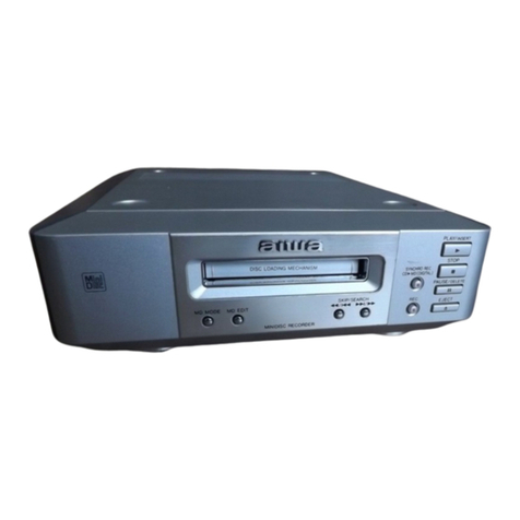
Aiwa AM-F90 User manual

SERVICE MANUAL
DATA
BASIC MD MECHANISM : MT-MZR900-171MINIDISC RECORDER
AM-F90
S/M Code No. 09-01A-355-4N2
AHK1 (S)

-2-
TABLE OF CONTENTS
SPECIFICATIONS .............................................................................................................................................. 3
ACCESSORIES/PACKAGE LIST-1/1 ................................................................................................................. 4
PROTECTION OF EYES FROM LASER BEAM DURING SERVICING ............................................................ 5
Optical Pickup Block and Base Unit Handling Precautions................................................................................. 6
Service Note........................................................................................................................................................ 7
DISASSEMBLY INSTRUCTIONS.................................................................................................................. 8-13
ELECTRICAL MAIN PARTS LIST ............................................................................................................... 14-17
BLOCK DIAGRAM-1/3 (SERVO) ...................................................................................................................... 18
BLOCK DIAGRAM-2/3 (AUDIO) ....................................................................................................................... 19
BLOCK DIAGRAM-3/3 (DISPLAY/KEY CONTROL/POWER) .......................................................................... 20
WIRING-1/1....................................................................................................................................................... 21
SCHEMATIC DIAGRAM-1/1 ............................................................................................................................. 22
WAVE FORM ............................................................................................................................................... 23-25
TEST MODE ................................................................................................................................................ 26-31
ELECTRICAL ADJUSTMENT...................................................................................................................... 32-42
IC BLOCK DIAGRAM................................................................................................................................... 43-45
IC DESCRIPTION-1/2 (CXA1782BQ)-1/1......................................................................................................... 46
IC DESCRIPTION-2/2 (CXD2671-203GACXD2671-203 GA) ..................................................................... 47-52
MECHANICAL EXPLODED VIEW-1/3 (MAIN UNIT)........................................................................................53
MECHANICAL EXPLODED VIEW-2/3 (MAIN C.B BLOCK) ............................................................................. 54
MECHANICAL EXPLODED VIEW-3/3 (MD MECHANISM DECK)................................................................... 55
MECHANICAL PARTS LIST-1/1................................................................................................................. 56, 57
APPENDIX1/1 ................................................................................................................................................... 58

-3-
SPECIFICATIONS
•
Design and specifications are subject to change without
notice.
•
Dolby noise reduction and HX Pro headroom extension
manufactured under license from Dolby Laboratories
Licensing Corporation. HX Pro originated by Bang &
Olufsen.
“DOLBY”, the double-D symbol
and “HX PRO”are
trademarks of Dolby Laboratories Licensing Corporation.
Laboratories Licensing Corporation.

-4-
REF. NO PART NO. KANRI DESCRIPTION
NO.
ACCESSORIES/PACKAGE LIST-1/1
1 8B-HM1-902-010 IB,HK(ECH)
2 8B-HM1-951-010 RC UNIT,RC-F90
3 87-B30-138-010 MIC,CM-MS001
4 87-B30-491-010 HEADPHONE,HP-M041(S) S-G
5 91-251-895-110 CASE,BAT UM-3
!
6 91-EM0-003-110 AC ADAPTOR,AMF90EX
7 91-756-120-110 BAT,NH-14WM(A)
8 93-043-060-010 CASE,BAT
9 93-220-749-010 CARRYNG,CASE
10 9X-337-932-120 CASE ASSY,BAT
11 91-EM0-007-110 OPTICAL CABLE

-5-
PROTECTION OF EYES FROM LASER BEAM DURING SERVICING
VAROITUS!
Laiteen Käyttäminen muulla kuin tässäkäyttöohjeessa mainit-
ulla tavalla saattaa altistaa käyt-täjän turvallisuusluokan 1 ylit-
tävälle näkymättömälle lasersäteilylle.
VARNING!
Om apparaten används påannat sätt än vad som specificeras i
denna bruksanvising, kan användaren utsättas för osynling
laserstrålning, som överskrider gränsen för laserklass 1.
Caution: Invisible laser radiation when
open and interlocks defeated avoid expo-
sure to beam.
Advarsel:Usynling laserståling ved åbning,
når sikkerhedsafbrydere er ude af funktion.
Undgåudsættelse for stråling.
CAUTION
Use of controls or adjustments or performance of procedures
other than those specified herein may result in hazardous
radiation exposure.
ATTENTION
L'utilisation de commandes, réglages ou procédures autres que
ceux spécifiés peut entraîner une dangereuse exposition aux
radiations.
ADVARSEL!
Usynlig laserståling ved åbning, når sikkerhedsafbrydereer ude
af funktion. Undgåudsættelse for stråling.
This Compact Disc player is classified as a CLASS 1 LASER
product.
The CLASS 1 LASER PRODUCT label is located on the rear
exterior.
This set employs laser. Therefore, be sure to follow carefully the
instructions below when servicing.
WARNING!
WHEN SERVICING, DO NOT APPROACH THE LASER EXIT
WITH THE EYE TOO CLOSELY. IN CASE IT IS NECESSARY TO
CONFIRM LASER BEAM EMISSION. BE SURE TO OBSERVE
FROM A DISTANCE OF MORE THAN 30cm FROM THE
SURFACE OF THE OBJECTIVE LENS ON THE OPTICAL
PICK-UP BLOCK.
CLASS 1
KLASSE 1
LUOKAN 1
KLASS 1
LASER PRODUCT
LASER PRODUKT
LASER LAITE
LASER APPARAT

-6-
Optical Pickup Block and Base Unit Handling Precautions
(LCX-4R)
The laser diode inside the optical pickup can be destroyed by
static electricity due to the static charge accumulated in human
body or in cloths.
Before starting the repair work of optical block and/or laser
diode, be very careful of the electrostatic breakdown because of
potential static electricity from clothing and your body. Follow the
same work procedures that are described in the printed material
supplied with the repair optical block. Also, the FLEX C.B can be
easily damaged. Be very careful when handling it.
Precaution when laser diode is emitting laser
NEVER LOOK into the laser diode from directly on top of the
laser diode. Doing so may result in loss of eyesight.
Precaution when handling the optical pickup (LCX-4R)
Because the laser diode inside the optical pickup can be very
easily destroyed by static electricity, short circuit the laser
taps of the FLEX C.B by solder-bridge before starting
handling the optical laser. At the same time, take the
sufficient preventive measures to protect the laser diode from
the static electricity. The FLEX C.B can be easily damaged.
Be very careful when handling it.
•If the MAIN C.B is removed when this machine is powered
on during repair, this machine will not work. Fix the protruded
portion ( portion) of the OPEN/CLOSE detection switch
(MAIN C.B S806) with adhesive tape in order to work this
machine.
•The FLEX C.B (Overwrite head) is connected to the MAIN
C.B directly by soldering. Be careful not to damage the FLEX
C.B (Overwrite head).
To perform any repair work on the component side of the
MAIN C.B, connect the FLEX C.B (Overwrite head) and the
MAIN C.B with the jumper leads before starting the repair
work. (Refer to DISASSEMBLY INSTRUCTIONS on page 9.)
* For replacement and repair of CDX2671-203 GA (IC801) that
is used in this machine, special tool is required.
Laser tap
Optical block FLEX C.B
PANEL ASSY, TOP
MAIN C.B
Tape
S806
FLEX C.B
(Overwrite head)
-7-
Service Note
•The sets that use the microprocessor version 1.000
are adjusted of their setup data by the MANUAL mode
in the factory before shipment. If the NV reset is
executed in these sets, the setup data will be cleared.
If the NV reset is executed in the sets of version 1.000,
change the adjustment value in accordance with the
adjustment value change procedure immediately after
the NV reset is executed. (Refer to ELECTRICAL
ADJUSTMENT page 32.)
•If non-volatile memory of this machine is replaced, the
program correction data must be written in the non-
volatile memory. After the non-volatile memory is
replaced, write the appropriate correction data that suit
to the version number of the microprocessor in
accordance with the patch data re-writing procedure
when the non-volatile memory is replaced. (Refer to
ELECTRICAL ADJUSTMENT page 37.)

-8-
DISASSEMBLY INSTRUCTIONS-1/6
If the numbers such as 1are shown in the illustration, disassemble the machine in the numerical order given in the illustration.
PANEL, BOTTOM
S801
S802
1
LID, BATTERY
4
Close the battery terminal (+).
KNOB, HOLD
5
Two screws ( 1.4)
3
LID, BATTERY
2
Claw
6
Remove the PANEL, BOTTOM in the
direction of the arrowA.
Screw ( 1.4)
5
Two screws
( 1.4)
Note :
When re-assembling, align the
position of the KNOB, HOLD
and that of the switches
(S801, S802).
PANEL ASSY, TOP
3
Two screws ( 1.4)
4
PANEL ASSY, TOP
1
FLEX C.B (CN801)
3
Two screws ( 1.4)
2
Open the PANEL ASSY, TOP by pressing the KNOB, OPEN.

-9-
DISASSEMBLY INSTRUCTIONS-2/6
LCD MODULE and PANEL, TOP
1 Five tapping screws (1.7)
3 PANEL, TOP
2 LCD MODULE
MAIN C.B ASSY
1 Remove soldering at the
two points on the FLEX
C.B (Overwrite head).
2 Connector (CN502).
6 Connector (CN501).
5
3 Four toothed machine screws
(M1.4).
7 MAIN C.B ASSY.
4 Screw ( 1.4)

-10-
DISASSEMBLY INSTRUCTIONS-3/6
BATTERY CASE ASSY, MAIN C.B
2 BATTERY CASE ASSY.
3 MAIN C.B .
1 Remove soldering of the
battery terminal (+).
1 Remove soldering of the
battery terminal (-).
CENTER FRAME ASSY
1 Pull in the direction of
the arrow Aand disengage
the boss aat the two locations.
2Open in the direction of the
arrow B, and disengage the
boss band the protruded
( ) portion at the two
locations.
4 Protruded ( )
portion at the two locations.
3Boss at the
three locations
5Remove the CENTER FRAME ASSY
in the direction of the arrow C.
Note:
The CENTER FRAME ASSY is
fragile and can be very easily broken.
Do not apply excessive force entirely.
b
B
B
A
A
C
a
a
b
b
2Open in the direction of the
arrow B, and disengage the
boss band the protruded
( ) portion at the two
locations.

-11-
MD MECHANISM DECK (MT-MZR900-171), CHASSIS ASSY
2 Protruded ( ) portion
4 Tension coil spring (arm).
5 CHASSIS ASSY
1 Screw ( 1.4)
3MD MECHANISM DECK
(MT-MZR900-171)
1 Screw ( 1.4)
2 Protruded ( ) portion
REPAIR OP ASSY (LCX-4R)
Overwrite head assy (OWH)
1Washer
(0.8-2.5)
2GEAR (SA)
3Precision screw
(M1.4)
4SPRING, RACK
5Screw for precision
equipment.
6Screw for precision
equipment (toothed screw).
7SPRING, THRUST RETAINER
8
9Remove the SCREW ASSY, LEAD.
0Bearing
!While opening the overwrite head assy
(OWH) in the direction of the arrow A,
remove the REPAIR OP ASSY (LCX-4R)
in the direction of the arrow B.
Note:
To open the overwrite head assy
(OWH), do not apply excessive
force entirely.
REPAIR OP ASSY
(LCX-4R)
DISASSEMBLY INSTRUCTIONS-4/6

-12-
HOLDER ASSY
D
1Open the HOLDER ASSY.
2Push the protruded ( ) portion
in the direction of the arrow B
and open the HOLDER ASSY
in the direction of the arrow A.
Stand the HOLDER ASSY in
the vertical position.
3Remove the recessed ( )
portion in the direction
of the arrow C.
4Protruded ( ) portion .
5Remove the HOLDER ASSY in the
direction of the arrow D.
A
B
C
MOTOR FLEX C.B
3MOTOR FLEX C.B .
1Remove soldering at the four locations
of the DC motor (sled) (M602).
1Remove soldering at the two locations of the DC motor
(overwrite head OWH UP/DOWN) (M603).
1Remove soldering at the four locations
of the DC motor (spindle) (M601).
2Peel off the release coated paper.
Note:
To install the MOTOR FLEX C.B,
align the round hole of the release
coated paper with the round hole of
the DC motor (sled).
Round hole of the
DC motor (sled)
DISASSEMBLY INSTRUCTIONS-5/6

-13-
DC motor (sled) (M602)
5DC motor (sled) (M602)
1Remove soldering at the four
locations of the MOTOR FLEX C.B.
2Washer (0.8-2.5)
3GEAR (SA)
4Two precision screws (M1.4)
DC motor (spindle) (M601), DC motor (overwrite head OWH UP/DOWN) (M603)
2.65mm
1Remove soldering at the six locations
of the MOTOR FLEX C.B.
2Washer (0.8-2.5)
3GEAR (HC)
4Three precision
screws (M1.4)
5DC motor
(spindle) (M601)
6Two screws ( 1.4)
7Washer (0.8-2.5)
8GEAR (HB)
9Screw
(M1.2 *1.5)
0GEAR (HA)
!DC motor (overwrite head
OWH UP/DOWN) (M603)
@Gear chassis assy
GEAR (HA)
Gear chassis assy
DC motor (overwrite head
OWH UP/DOWN) (M603)
Note:
To install the GEAR (HA) into the DC motor
(overwrite head OWH UP/DOWN) (M603),
press-fit it to the position shown in the illustration.
DISASSEMBLY INSTRUCTIONS-6/6

-14-
REF. NO PART NO. KANRI DESCRIPTION
NO. REF. NO PART NO. KANRI DESCRIPTION
NO.
ELECTRICAL MAIN PARTS LIST-1/4
MAIN C.B
C101 91-125-837-910 C-CAP,CER 1-6.3
C103 91-125-837-910 C-CAP,CER 1-6.3
C104 91-135-868-910 C-CAP,TN 220-2.5
C105 91-113-600-910 C-CAP,TN 2.2-6.3
C106 91-164-939-810 C-CAP,CER 2200P-16
C110 91-125-837-910 C-CAP,CER 1-6.3
C111 91-164-874-810 C-CAP,CER 100P-16
C112 91-125-837-910 C-CAP,CER 1-6.3
C113 91-131-862-910 C-CAP,TN 47-4
C116 91-164-937-810 C-CAP,CER 1000P-16
C117 91-125-777-810 C-CAP,CER 0.1-10
C118 91-164-939-810 C-CAP,CER 2200P-16
C201 91-125-837-910 C-CAP,CER 1-6.3
C203 91-125-837-910 C-CAP,CER 1-6.3
C204 91-135-868-910 C-CAP,TN 220-2.5
C205 91-113-600-910 C-CAP,TN 2.2-6.3
C206 91-164-939-810 C-CAP,CER 2200P-16
C210 91-125-837-910 C-CAP,CER 1-6.3
C211 91-164-874-810 C-CAP,CER 100P-16
C212 91-125-837-910 C-CAP,CER 1-6.3
C213 91-131-862-910 C-CAP,TN 47-4
C216 91-164-937-810 C-CAP,CER 1000P-16
C217 91-125-777-810 C-CAP,CER 0.1-10
C218 91-164-939-810 C-CAP,CER 2200P-16
C301 91-131-725-910 C-CAP,TN 47-6.3
C302 91-107-820-810 C-CAP,CER 0.1-16
C303 91-117-919-910 C-CAP,TN 10-6.3
C304 91-107-820-810 C-CAP,CER 0.1-16
C305 91-113-600-910 C-CAP,TN 2.2-6.3
C306 91-107-820-810 C-CAP,CER 0.1-16
C307 91-125-777-810 C-CAP,CER 0.1-10
C308 91-107-820-810 C-CAP,CER 0.1-16
C309 91-127-895-910 C-CAP,TN 22-4
C310 91-125-899-910 C-CAP,TN 220-4
C311 91-128-964-910 C-CAP,TN 100-6.3
C312 91-127-895-910 C-CAP,TN 22-4
C313 91-127-895-910 C-CAP,TN 22-4
C314 91-119-923-810 C-CAP,CER 0.047-10
C315 91-127-578-910 C-CAP,TN 3.3-6.3
C316 91-131-734-210 C-CAP,TN 4.7-6.3
C318 91-125-777-810 C-CAP,CER 0.1-10
C320 91-117-919-910 C-CAP,TN 10-6.3
C321 91-125-777-810 C-CAP,CER 0.1-10
C322 91-131-862-910 C-CAP,TN 47-4
C323 91-117-919-910 C-CAP,TN 10-6.3
C329 91-125-777-810 C-CAP,CER 0.1-10
C330 91-107-820-810 C-CAP,CER 0.1-16
C332 91-117-919-910 C-CAP,TN 10-6.3
C334 91-117-919-910 C-CAP,TN 10-6.3
C335 91-164-933-810 C-CAP,CER 220P-16
C336 91-125-837-910 C-CAP,CER 1-6.3
C337 91-117-863-910 C-CAP,0.47-6.3
C338 91-164-874-810 C-CAP,CER 100P-16
C340 91-125-777-810 C-CAP,CER 0.1-10
C344 91-164-943-810 C-CAP,CER 0.01-16
C501 91-164-874-810 C-CAP,CER 100P-16
C502 91-127-772-810 C-CAP,CER 0.033-10
C503 91-164-940-810 C-CAP,CER 3300P-16
C504 91-164-940-810 C-CAP,CER 3300P-16
C505 91-164-943-810 C-CAP,CER 0.01-16
C506 91-127-772-810 C-CAP,CER 0.033-10
C507 91-127-772-810 C-CAP,CER 0.033-10
C508 91-164-938-810 C-CAP,CER 1500P-16
C509 91-164-940-810 C-CAP,CER 3300P-16
C510 91-164-850-810 C-CAP,CER 10P-16
C511 91-164-850-810 C-CAP,CER 10P-16
C512 91-125-777-810 C-CAP,CER 0.1-10
C513 91-164-850-810 C-CAP,CER 10P-16
C514 91-107-819-810 C-CAP,CER 0.022-16
C515 91-125-777-810 C-CAP,CER 0.1-10
C516 91-125-777-810 C-CAP,CER 0.1-10
C518 91-131-734-210 C-CAP,TN 4.7-6.3
C519 91-164-940-810 C-CAP,CER 3300P-16
C521 91-125-777-810 C-CAP,CER 0.1-10
C522 91-125-777-810 C-CAP,CER 0.1-10
C523 91-125-837-910 C-CAP,CER 1-6.3
C524 91-117-919-910 C-CAP,TN 10-6.3
C526 91-125-777-810 C-CAP,CER 0.1-10
C529 91-125-840-910 CAP,TN 10-6.3
C530 91-164-939-810 C-CAP,CER 2200P-16
C532 91-119-923-810 C-CAP,CER 0.047-10
C551 91-125-837-910 C-CAP,CER 1-6.3
C552 91-125-837-910 C-CAP,CER 1-6.3
C553 91-127-578-910 C-CAP,TN 3.3-6.3
C554 91-127-578-910 C-CAP,TN 3.3-6.3
C555 91-131-621-910 C-CAP,TN 6.8-6.3
C556 91-131-621-910 C-CAP,TN 6.8-6.3
C557 91-127-772-810 C-CAP,CER 0.033-10
C558 91-127-772-810 C-CAP,CER 0.033-10
C559 91-127-772-810 C-CAP,CER 0.033-10
C561 91-125-777-810 C-CAP,CER 0.1-10
C601 91-164-943-810 C-CAP,CER 0.01-16
C602 91-125-777-810 C-CAP,CER 0.1-10
C603 91-125-839-910 C-CAP,TN 47-6.3
C604 91-164-943-810 C-CAP,CER 0.01-16
C605 91-164-937-810 C-CAP,CER 1000P-16
C606 91-164-874-810 C-CAP,CER 100P-16
C607 91-164-874-810 C-CAP,CER 100P-16
C608 91-125-777-810 C-CAP,CER 0.1-10
C609 91-137-762-910 C-CAP,TN 10-4
C610 91-137-704-910 C-CAP,TN 10-10
C611 91-117-919-910 C-CAP,TN 10-6.3
C612 91-117-919-910 C-CAP,TN 10-6.3
C613 91-125-777-810 C-CAP,CER 0.1-10
C614 91-125-777-810 C-CAP,CER 0.1-10
C615 91-137-760-910 C-CAP,M 100P-100
C616 91-125-777-810 C-CAP,CER 0.1-10
C618 91-125-777-810 C-CAP,CER 0.1-10
C619 91-125-777-810 C-CAP,CER 0.1-10
C621 91-164-943-810 C-CAP,CER 0.01-16
C623 91-127-895-910 C-CAP,TN 22-4
C624 91-127-895-910 C-CAP,TN 22-4
C625 91-131-862-910 C-CAP,TN 47-4
C626 91-125-839-910 C-CAP,TN 47-6.3
C629 91-164-943-810 C-CAP,CER 0.01-16
C630 91-164-874-810 C-CAP,CER 100P-16
C631 91-117-919-910 C-CAP,TN 10-6.3
C633 91-125-777-810 C-CAP,CER 0.1-10
C801 91-125-777-810 C-CAP,CER 0.1-10
C802 91-164-943-810 C-CAP,CER 0.01-16
C803 91-164-943-810 C-CAP,CER 0.01-16
C804 91-125-777-810 C-CAP,CER 0.1-10
C805 91-119-923-810 C-CAP,CER 0.047-10
C806 91-119-923-810 C-CAP,CER 0.047-10
C807 91-164-850-810 C-CAP,CER 10P-16
C808 91-164-850-810 C-CAP,CER 10P-16
C809 91-117-919-910 C-CAP,TN 10-6.3
C810 91-125-837-910 C-CAP,CER 1-6.3
C811 91-125-837-910 C-CAP,CER 1-6.3
C812 91-164-943-810 C-CAP,CER 0.01-16
C813 91-125-891-910 C-CAP,CER 0.47-10
C814 91-164-935-810 C-CAP,CER 470P-16
C815 91-131-725-910 C-CAP,TN 47-6.3
C816 91-125-777-810 C-CAP,CER 0.1-10
C817 91-125-837-910 C-CAP,CER 1-6.3

-15-
REF. NO PART NO. KANRI DESCRIPTION
NO. REF. NO PART NO. KANRI DESCRIPTION
NO.
ELECTRICAL MAIN PARTS LIST-2/4
C818 91-125-777-810 C-CAP,CER 0.1-10
C819 91-127-772-810 C-CAP,CER 0.033-10
C820 91-127-772-810 C-CAP,CER 0.033-10
C821 91-127-895-910 C-CAP,TN 22-4
C822 91-125-777-810 C-CAP,CER 0.1-10
C823 91-107-820-810 C-CAP,CER 0.1-16
C825 91-125-777-810 C-CAP,CER 0.1-10
C826 91-127-715-910 C-CAP,CER 0.22-16
C827 91-164-850-810 C-CAP,CER 10P-16
C828 91-125-837-910 C-CAP,CER 1-6.3
C829 91-127-715-910 C-CAP,CER 0.22-16
C830 91-117-919-910 C-CAP,TN 10-6.3
C831 91-128-964-910 C-CAP,TN 100-6.3
C832 91-107-820-810 C-CAP,CER 0.1-16
C833 91-164-874-810 C-CAP,CER 100P-16
C834 91-125-777-810 C-CAP,CER 0.1-10
C835 91-125-777-810 C-CAP,CER 0.1-10
C836 91-125-777-810 C-CAP,CER 0.1-10
C837 91-125-777-810 C-CAP,CER 0.1-10
C901 91-125-840-910 CAP,TN 10-6.3
C902 91-137-762-910 C-CAP,TN 10-4
C903 91-128-964-910 C-CAP,TN 100-6.3
C904 91-137-762-910 C-CAP,TN 10-4
C905 91-125-777-810 C-CAP,CER 0.1-10
C906 91-164-943-810 C-CAP,CER 0.01-16
C907 91-125-889-910 C-CAP,CER 2.2-10
C908 91-125-777-810 C-CAP,CER 0.1-10
C911 91-117-919-910 C-CAP,TN 10-6.3
C913 91-164-941-810 C-CAP,CER 4700P-16
C914 91-125-777-810 C-CAP,CER 0.1-10
C915 91-125-777-810 C-CAP,CER 0.1-10
C917 91-125-777-810 C-CAP,CER 0.1-10
C919 91-117-919-910 C-CAP,TN 10-6.3
C920 91-117-919-910 C-CAP,TN 10-6.3
C921 91-125-777-810 C-CAP,CER 0.1-10
C922 91-164-937-810 C-CAP,CER 1000P-16
C923 91-125-891-910 C-CAP,CER 0.47-10
C924 91-125-891-910 C-CAP,CER 0.47-10
C925 91-125-891-910 C-CAP,CER 0.47-10
C926 91-164-937-810 C-CAP,CER 1000P-16
C932 91-125-777-810 C-CAP,CER 0.1-10
CN501 91-778-168-210 CONN,20P
CN502 91-794-756-210 CONN,15P
CN801 91-794-755-210 CONN,18P
D301 98-719-081-740 DIODE,DF8A6.8FK
D302 98-719-081-730 DIODE,DF3A6.8FE
D303 98-719-046-900 DIODE,MA2S111
D601 98-719-081-330 DIODE,MA2YD1500LS0
D602 98-719-081-330 DIODE,MA2YD1500LS0
D603 98-719-081-340 DIODE,RB160M-30TR
D605 98-719-081-340 DIODE,RB160M-30TR
D606 98-719-081-350 DIODE,MA2YD1700LS0
D607 98-719-081-330 DIODE,MA2YD1500LS0
D608 98-719-081-350 DIODE,MA2YD1700LS0
D801 98-719-056-540 DIODE,MAZS068008SO
D901 98-719-081-330 DIODE,MA2YD1500LS0
D902 98-719-081-330 DIODE,MA2YD1500LS0
D903 98-719-420-520 DIODE,MA729
D904 98-719-404-500 DIODE,MA111
!
F801 91-576-439-210 FUSE,0.25A-125V
FB301 91-216-864-910 C-RES,0-1/16
FB302 91-216-864-910 C-RES,0-1/16
FB303 91-216-809-910 C-RES,100-1/16
FB304 91-216-809-910 C-RES,100-1/16
FB305 91-216-864-910 C-RES,0-1/16
FB306 91-216-864-910 C-RES,0-1/16
FB801 91-216-864-910 C-RES,0-1/16
FB802 91-216-864-910 C-RES,0-1/16
FB803 91-216-864-910 C-RES,0-1/16
FB804 91-216-864-910 C-RES,0-1/16
IC301 98-759-829-440 IC,AK4562VN-L
IC302 98-759-829-770 IC,AN7536FHNEBV
IC303 98-759-699-540 IC,NJM2173APC1
IC501 98-759-689-670 IC,SN761057DBT
IC551 98-759-698-620 IC,SC111257FCR2
IC601 98-759-698-600 IC,XPC18A22FCR2
IC801 98-752-410-490 IC,CXD2671-203GA
IC804 98-759-680-850 IC,AK6417AL-L
IC805 98-759-196-970 IC,TC7SH32FU-TE85R
IC901 98-759-698-610 IC,XPC18A32FCR2
J301 91-793-619-210 JACK,LINE IN
J302 91-793-509-110 JACK,PHON
J303 91-793-620-210 JACK,MIC
J601 91-785-383-110 JACK,DC
L301 91-469-535-210 C-COIL,10U
L302 91-469-535-210 C-COIL,10U
L303 91-469-535-210 C-COIL,10U
L501 91-469-535-210 C-COIL,10U
L502 91-469-535-210 C-COIL,10U
L551 91-414-402-410 C-COIL,47U
L552 91-414-402-410 C-COIL,47U
L553 91-469-422-210 COIL,22U
L554 91-469-422-210 COIL,22U
L601 91-419-959-210 COIL,6.8U
L602 91-469-535-210 C-COIL,10U
L603 91-469-535-210 C-COIL,10U
L801 91-469-535-210 C-COIL,10U
L802 91-469-535-210 C-COIL,10U
L901 91-419-952-210 COIL,68U
L902 91-419-949-210 COIL,22U
L903 91-469-367-210 CIOL,10U
L904 91-414-398-410 COIL,10U
L905 91-469-426-210 COIL,100U
Q302 98-729-046-490 FET,FDV304P
Q501 98-729-922-110 TR,2SA1577-QR
Q601 98-729-046-450 FET,SI2302DS-T1
Q602 98-729-046-440 TR,ZDT6718TA
Q603 98-729-053-710 TR,TS8K1TB
Q604 98-729-046-430 FET,HAT2051T-EL
Q605 98-729-046-420 FET,HAT2050T-EL
Q801 98-729-429-460 TR,XP1501
Q803 98-729-029-140 TR,DTC144EUA-T106
R101 91-208-907-810 C-RES,6.8K-1/16-0.5
R103 91-218-965-810 C-RES,10K-1/16
R104 91-218-990-810 C-RES,0-1/16
R111 91-208-919-810 C-RES,22K-1/16-0.5
R112 91-208-927-810 C-RES,47K-1/16-0.5
R118 91-208-907-810 C-RES,6.8K-1/16-0.5
R201 91-208-907-810 C-RES,6.8K-1/16-0.5
R203 91-218-965-810 C-RES,10K-1/16
R204 91-218-990-810 C-RES,0-1/16
R211 91-208-919-810 C-RES,22K-1/16-0.5
R212 91-208-927-810 C-RES,47K-1/16-0.5
R218 91-208-907-810 C-RES,6.8K-1/16-0.5
R301 91-208-911-810 C-RES,10K-1/16-0.5
R302 91-218-953-810 C-RES,1K-1/16
R303 91-218-983-810 C-RES,330K-1/16
R304 91-218-953-810 C-RES,1K-1/16
R305 91-218-953-810 C-RES,1K-1/16
R306 91-218-985-810 C-RES,470K-1/16
R307 91-218-941-810 C-RES,100-1/16
R308 91-218-989-810 C-RES,1M-1/16
R309 91-208-943-810 C-RES,220K-1/16-0.5
R310 91-218-957-810 C-RES,2.2K-1/16
R312 91-218-990-810 C-RES,0-1/16
R317 91-218-941-810 C-RES,100-1/16
R318 91-218-941-810 C-RES,100-1/16
R319 91-218-941-810 C-RES,100-1/16
R501 91-218-971-810 C-RES,33K-1/16
R505 91-208-907-810 C-RES,6.8K-1/16-0.5

-16-
REF. NO PART NO. KANRI DESCRIPTION
NO. REF. NO PART NO. KANRI DESCRIPTION
NO.
ELECTRICAL MAIN PARTS LIST-3/4
R507 91-218-953-810 C-RES,1K-1/16
R517 91-208-895-810 C-RES,2.2K-1/16-0.5
R519 91-218-977-810 C-RES,100K-1/16
R521 91-218-446-910 C-RES,1-1/16
R601 91-218-989-810 C-RES,1M-1/16
R602 91-218-981-810 C-RES,220K-1/16
R603 91-218-977-810 C-RES,100K-1/16
R604 91-219-724-910 C-RES,1-1/4-1
R605 91-242-996-910 C-RES,0.68-1/4
R606 91-218-949-810 C-RES,470-1/16
R607 91-218-945-810 C-RES,220-1/16
R608 91-218-983-810 C-RES,330K-1/16
R609 91-219-724-910 C-RES,1-1/4-1
R610 91-218-990-810 C-RES,0-1/16
R611 91-218-990-810 C-RES,0-1/16
R613 91-218-957-810 C-RES,2.2K-1/16
R619 91-218-990-810 C-RES,0-1/16
R620 91-218-965-810 C-RES,10K-1/16
R621 91-218-965-810 C-RES,10K-1/16
R622 91-216-797-910 C-RES,10-1/16
R801 91-218-981-810 C-RES,220K-1/16
R802 91-208-927-810 C-RES,47K-1/16-0.5
R803 91-208-927-810 C-RES,47K-1/16-0.5
R804 91-218-959-810 C-RES,3.3K-1/16
R805 91-218-959-810 C-RES,3.3K-1/16
R806 91-218-951-810 C-RES,680-1/16
R807 91-218-929-810 C-RES,10-1/16
R808 91-218-965-810 C-RES,10K-1/16
R809 91-218-977-810 C-RES,100K-1/16
R810 91-208-919-810 C-RES,22K-1/16-0.5
R811 91-218-983-810 C-RES,330K-1/16
R812 91-208-939-810 C-RES,150K-1/16-0.5
R813 91-218-989-810 C-RES,1M-1/16
R814 91-218-929-810 C-RES,10-1/16
R815 91-218-971-810 C-RES,33K-1/16
R816 91-218-953-810 C-RES,1K-1/16
R817 91-218-977-810 C-RES,100K-1/16
R821 91-218-981-810 C-RES,220K-1/16
R822 91-218-953-810 C-RES,1K-1/16
R823 91-218-945-810 C-RES,220-1/16
R824 91-218-959-810 C-RES,3.3K-1/16
R825 91-202-974-810 C-RES,3.3M-1/16
R828 91-208-895-810 C-RES,2.2K-1/16-0.5
R829 91-208-895-810 C-RES,2.2K-1/16-0.5
R830 91-218-989-810 C-RES,1M-1/16
R831 91-218-990-810 C-RES,0-1/16
R832 91-218-990-810 C-RES,0-1/16
R833 91-218-990-810 C-RES,0-1/16
R834 91-218-990-810 C-RES,0-1/16
R837 91-218-990-810 C-RES,0-1/16
R838 91-218-990-810 C-RES,0-1/16
R839 91-218-990-810 C-RES,0-1/16
R840 91-218-990-810 C-RES,0-1/16
R841 91-216-809-910 C-RES,100-1/16
R844 91-216-864-910 C-RES,0-1/16
R845 91-218-990-810 C-RES,0-1/16
R846 91-218-941-810 C-RES,100-1/16
R902 91-218-985-810 C-RES,470K-1/16
R903 91-218-957-810 C-RES,2.2K-1/16
R905 91-218-957-810 C-RES,2.2K-1/16
R906 91-218-990-810 C-RES,0-1/16
R907 91-218-985-810 C-RES,470K-1/16
R908 91-218-977-810 C-RES,100K-1/16
R909 91-218-965-810 C-RES,10K-1/16
R910 91-218-965-810 C-RES,10K-1/16
R911 91-218-949-810 C-RES,470-1/16
R912 91-218-987-810 C-RES,680K-1/16
R915 91-218-941-810 C-RES,100-1/16
R917 91-218-990-810 C-RES,0-1/16
R920 91-208-911-810 C-RES,10K-1/16-0.5
R921 91-218-979-810 C-RES,150K-1/16
R936 91-218-977-810 C-RES,100K-1/16
R941 91-218-971-810 C-RES,33K-1/16
R946 91-208-919-810 C-RES,22K-1/16-0.5
R947 91-218-985-810 C-RES,470K-1/16
R948 91-208-939-810 C-RES,150K-1/16-0.5
R949 91-218-989-810 C-RES,1M-1/16
RB551 91-233-959-210 C-ARRAY,470
RB552 91-233-973-210 C-ARRAY,100K
RB553 91-233-967-210 C-AARAY,10K
RB801 91-233-973-210 C-ARRAY,100K
S801 91-786-030-210 SW,SL HOLD
S802 91-786-030-210 SW,SL HOLD
S803 91-771-860-210 SW,PUSH PROTECT
S804 91-771-806-610 SW,PUSH BAT
S805 91-762-947-120 SW,PUSH OPEN
S806 91-762-805-210 SW,PUSH OPEN/CLOSE
T601 91-416-405-210 C-FLTR,EMI
TH601 91-533-817-210 THMS,CDU415-10
X801 91-795-000-210 VIB,X’TAL,45.1584M

-17-
88
A
Resistor Code
Chip Resistor Part Coding
Figure
Value of resistor
Chip resistor
Wattage Type Tolerance
1/16W
1/10W
1/8W
1608
2125
3216
5%
5%
5%
CJ
CJ
CJ
Form LW t
1.6 0.8 0.45
2 1.25 0.45
3.2 1.6
108
118
128
: A
: A
CHIP RESISTOR PART CODE
0.55
Resistor Code
Dimensions (mm)
Symbol
1/16W 1005 5% CJ 1.0 0.5 0.35 104
Lt
W
• Regarding connectors, they are not stocked as they are not the initial order items.
The connectors are available after they are supplied from connector manufacturers upon the order is received.
ELECTRICAL MAIN PARTS LIST-4/4

-18-
BLOCK DIAGRAM-1/3 (SERVO)
33
29
28
41
42
1
44
21
31
26
25
43
24
23
4
8
9
10
11
12
14
5
6
13
7
18 19
JX JY JX
IX IY
IY
IX
JX
JY
A
B
C
D
MON
IX
A
F
BCD
OPTICAL PICK-UP BLOCK
(LCX-4R)
HR601
OVER
WRITE
HEAD
S0
S1
D
D-C
PD-NI
PD-O
C
B
A
VREF
A-C
JY
JX
IX
IY
RF AMP,
FOCUS
ERROR,
TRACKING
ERROR
TPP/WPP
APC
S-MONITER
RF OUT
PEAK
BOTM
ABCD
FE
ADIP IN
TE
ADIP
PD-I
OFTRK
VC
SBUS
SCK
S-MON
RESET
PEAK
/BOTM
RF AMP, FOCUS/TRACKING ERROR AMP
IC501
M603
OVER WRITE
HEAD
UP/DOWN
+
–
+
–
+
–
+
–
+
–
+
–
+
–
+
–
+
–
AUTOMATIC
POWER
CONTROL
Q501
20
LD
SERIAL
INTERFACE
TRK+
FCS+
FCS–
FCS+
FCS–
TRK–
TRK+
TRK–
37
44
45
46
47
56
74
49
12
217
221
9
161
194
195
160
78
35
33
41
38 37
42
25 38
31
1 2 3 5 6
199 198 197 201 200
4
7
CHARGE
PUMP 2
27
28
CHARGE
PUMP 1
100
101
93
94
95
87
223
88
166
102
99
97
98
96
233
83
82
80
81
18
19
24
25
8
10
35
33
89
90
2731
26
20
16
17
3
2
46
44
55 56 1
6220
14
12
41
29
42
40
39
38
37
4
5
48
53
52
51
54
105
62
68
67
LD-A
(TRACKING)
(FOCUS)
2-AXIS
DEVICE
OVER WRITE
HEAD DRIVE
Q604, 605
MM
EFM
PRE DRIVER
H-BRIDGE
PRE DRIVER
SYSTEM CONTROL (1/2)
HB
HA
OUTA
OUTB
VREF
C1H
C1L
C2H
C2L
VRECIN2
CLK
EFM
VRECIN1 VRECO
B+
SW
RECON
OE
RI
FI
MODE3
MODE2
MODE1
HD CON2
HD CON1
EFMD
OVER WRITE HEAD DRIVE
IC601 (1/2)
RFI
PEAK
BOTM
ABCD
FE
TE
ADIP
VC
VREF MON
OFTRK
XRF RST
S MON
M602
(SLED)
SSB CLK
PD S0
PD S1
SSB DATA
APCREF
SYSTEM CONTROLLER,
DIGITAL SIGNAL PROCESSOR,
16M BIT D-RAM
IC801 (1/3)
SIGNAL PATH
: PLAY BACK
: REC (ANALOG IN)
: REC (DIGITAL IN)
A
B
C
D
DIN1
ADDT
DADT
DIN1
ADDT
DADT
CLK
E
VREF
SLCU
SLCV
SPCU
SPCV
SPCW
SLD1 MON
SLD2 MON
CLV MON U
CLV MON V
CLV MON W
SPDU
SPDL MON
SPFD/SPVS/PWM3
SPDL AUX PWM
SLCW
SLDW
SFDR
SLDV
SLDR
SLD MON
FRDR
FFDR
TRDR
TFDR
SPDV
SPDW
XRST MTR DRV
SPINDLE
SERVO
DRIVE
SWITCH
IC805
RI1
FI1
RI3
FI3
RI4
FI4
PWMI4
RI2
FI2
VI
WI
CPWO
CPVO
CPUO
CLV MON W
CLV MON V
CLV MON U
OF
UI
PWM
RO1
FO1
RO3
FO3
FCS–
FCS+
TRK–
TRK+
RO4
VO
WO
FO2
RO2
CPAIM
FO4
CPAIP
CPBIP
CPBIM
CPA0
SLD 2 MON
SLD 1 MON
CPB0
UO
CPUI
CPVI
CPWI
COM
TRACKING
COIL DRIVE
FOCUS
COIL DRIVE
SLED VOLTAGE
MONITER
SPINDLE
VOLTAGE MONITOR
SLED
MOTOR
DRIVE
SPINDLE
MOTOR
DRIVE
FOCUS/TRACKING
COIL DRIVE,
SPINDLE/SLED
MOTOR DRIVE
IC551
BIAS
M601
(SPINDLE)
MM
U
WV

-19-
BLOCK DIAGRAM-2/3 (AUDIO)
VC B+ F801
F
RMC KEY
RVDD
DTCK
CDWM 2V
CDWM DATA
KEY-R
RGND
(LINE IN JACK)
OPTICAL
RECEIVER
J302
/LINE OUT
J301
LINE IN
(OPT)
J303
MIC
(PLUG IN POWER)
SIGNAL PATH
: PLAY BACK
: REC (ANALOG IN)
: REC (DIGITAL IN)
2
1113
5
4
16
10
9
12
13
3
1
14 15 16
183 186 178
AOUT
SEL
143
142
144
145
192215 191 2193
5
7
4
6
2
3
27
1
26
28
19
71
25
6970
25
23
22
21
20
17
16
15
179
180
181
1
219
234
B+ SWITCH
Q302
VIF B+
REGULATOR
MUTING
MIC AMP
IC303
IN2
IN1
STBY
GV
OUT1
OUT2
HP/LINE
SWITCH
GAIN
AMP
GAIN
AMP
CLOCK
DIVIDER
D/A
CONVERTER
AUDIO
I/F
CONTROL
CONTROL
REGISTER
I/F
D/A
CONVERTER
&
HPF
HEADPNONE AMP
IC302
LOUT
ROUT
GA-L
GA-R
L-IN
R-IN
HP/L
MUTE
BEEP
210 TSB SLAVE
DETECT
Q803
BEEP
XMUTE
XJAC DET
XOPT CTL
FS256
LRCK
XBCK
OSCO
OSCI
XCS NV
SDIO
SCK0
SDO0
OPT DET
MIC SENSE
XMIC DET
TSB SLV VDD
RMC DTCK
TSB SLVI
TSB SLVO
TSB SLV CHK
SYSTEM CONTROLLER,
DIGITAL SIGNAL PROCESSOR
16M BIT D-RAM
IC801 (2/3)
RIN1
RIN2
LIN1
LIN2
A/D, D/A
CONVERTER
IC301
LOUT2
ROUT2
OPGAL
OPGAR
24
X801
45.1584MHz
SIO
SO0
SCK0
SDI0
SDO0
SCK0
SCK0
SDO0
DADT
ADDT
DIN1
SDO0, SDI0, SCK0
XCS
SK
DI
DO
LOUT1
ROUT2
MCLK
SDTO
SDTI
BCLK
CCLK
CSN
SSB
LRCK
CDTI
B
A
C
G
EEPROM
IC804

-20-
BLOCK DIAGRAM-3/3 (DISPLAY/KEY CONTROL/POWER)
7
4
56
52
54
55
1
2
3
5
20
86
169
236
235
234
17
18
19
6
10
49
24
25
39
44
38
42
40
41
35
22
23
26
46
47 50
28
32
34
11
14
10
15
22
16
19
20
51
54
55
21
8
9
26
49
47
46
45
43
44
56
50
48
33
36
45
18
19
16
12
10
9
27
53
+–
15
164
165
8
163
48
11
237
238
16
171
10
216
1
208
13
14
228
170
205
206
187
182
230
3
227
VB
HEADPHONE AMP (IC302),
MOTOR/COIL DRIVER (IC551)
B+
POWER CONTROL
IC901
SWITCHING
REGURATOR
SYSTEM
CONTROL
BANDGAP
REFERENCE
SERIES
PASS
REGULATOR
REGURATOR
STEP-UP
DC/DC
CONVERTER
STEP-UP
PRE DRIVER
&
PWM
D902
D903
L902
L905
VG
MOTOR/COIL
DRIVER (IC551)
B+
VL
VL
VG
LG
VC2
VC
VC
VOUT
L1
L1
VB
L2
L2
RF2
VB
VC
VRMC
XWK3
CLK
CLK SEL
FFCLR
SLEEP
VLON
XWK1
XWK2
XWK4
VAIFON
VSTB
VLO
VREF
DTC2
DTC1
VDFB
VIFFB
VIF
VAFB
VA
VCO
INM2
INM1
RF2
RF1
XRST
CRST DTC1
VD
D904
L801
L904
VSTB
SYSTEM CONTROLLER (IC801)
B+
SYSTEM CONTROLLER
IC801 (3/3)
RMC KEY
CLK
VRFF
SDO0, SDI0, SCK0
VL
LASER APC CIRCUIT
B+
VD
SYSTEM CONTROLLER (IC801)
B+
VIF
A/D, D/A CONVERTER (IC301),
SYSTEM CONTROLLER (IC801),
EEPROM (IC804)
B+
VA
A/D, D/A CONVERTER (IC301),
SYSTEM CONTROLLRE (IC801)
B+
VC
MIC AMP (IC303),
RF AMP (IC501),
MOTOR/COIL DRIVER (IC551),
REMOTE CONTROL CIRCUIT
B+
RMC KEY
FS4
CLK SEL
FFCLR
SLEEP
VLON
WK DET
REC KEY
HALF LOCK SW
VL MON
OPEN
S805
CS RTC
VIF B+
VB B+
XCS LCD
LCD STB
LCD RST AUX
F
D
E
G
LCD
DRIVER
&
REAL TIME
CLOCK
LCD
SDO0
SDI0
SCK0
SD0
SI0
SCK
RST
STB
CS
CS RTC
REC
PAUSE
REC LED
SE1 KEY 1
SE1 KEY 2
DVDD
BACKUP
UNREG
XWK1
REC
T MARK
REC MODE
END SEATCH
+–
HOLD
S801
OFF
HOLD
SYNCHRO REC
S802
ON
OFF
–– VOL
REC
+
,
,
,
,,
(JOG LEVER L/R)
VIF B+
VB B+
SWITCH & LCD MUDULE UNIT
SL801
(TEST)
S803
PROTECT
DETECT
S804
BATTERY IN
DETECT
S806
OPEN/CLOSE
DETECT
SYNC REC
OPEN CLOSE SW
XGUM ON
PROTECT
XTEST
AUXI
CHG MON
CHG GAIN
CHG
HIDC MON
GND SW
VB MON
PAUSE KEY
REC LED
SET KEY1
SET KEY2
XHOLD SW
VIF B+
VB B+
VL PWM
VC PWM
XRST
VREC PWM
RESET
SWITCH
Q801
NOISE
FILTER
NOISE
FILTER
NOISE
FILTER
L603
L602
VRECO
OVER WRITE
HEAD DRIVE
CIRCUIT
B+ SWITCH
SWITCHING
REGULATOR
RESET SIGNAL
GENERATOR
SWITCHING
REGULATOR
CHARGE
CONTROL
CHARGE
MONITOR
POWER
CONTROL
IC601 (2/2)
STEP-UP DOWN
PRE DRIVER
&
PWM
STEP-UP
PRE DRIVER
&
PWM
BATTERY
CHARGER
&
REGULATOR
SYSTEM
CONTROL
(2/2)
VRECO1
VRECO2
VREC
INM1
RF1
CHGMON
GAIN
CHG
L1 1
L1 2
DW BT
DW TP
VIO
VC2
VC
RF2
INM2
INP2
RS
CHG SW
VB
BATM
DREG
DCIN
VIF
B+
D605
VC B+
VIF B+
L601
L901
D901
L903
D603
B+ SWITCH
Q603
CHARGE
CONTROL
Q602 (2/2)
CHARGE
CONTROL
Q602 (1/2)
LINE
FILTER
T601
CHARGE
RECHARGEABLE
BATTERY
(NICKEL-METAL)
NH-14WM (A)
1.2V 1400mAh
–+
DC IN 3V
J601
GROUND
LINE
SWITCHING
Q601
THP601
(BATTERY CASE)
DRY BATTERY
SIZE “AA”
IEC DESIGNATION
R6
1PC. 1.5V
REGULATOR
SWITCH
This manual suits for next models
2
Table of contents
Other Aiwa Mini Disc Recorder manuals

Aiwa
Aiwa AM-F70 - ANNEXE 23 Building instructions

Aiwa
Aiwa AM-F80 User manual

Aiwa
Aiwa AM-F80 User manual

Aiwa
Aiwa AM-C75 User manual

Aiwa
Aiwa AM-F70 - ANNEXE 23 Building instructions

Aiwa
Aiwa AM-F70 - ANNEXE 23 User manual

Aiwa
Aiwa AM-C80 User manual

Aiwa
Aiwa AM-C80 User manual

Aiwa
Aiwa AM-LM918 User manual

Aiwa
Aiwa AM-C75 User manual