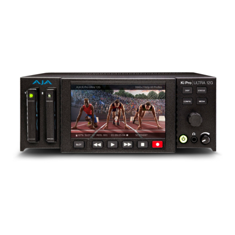
AJA Ki PRO ULTRA Use and maintenance manual

Machine Control Guide
Ki Pro Ultra Products
Version 3.0
Published May 27, 2020

Ki Pro Ultra Products Machine Control Guide v3.0 2 www.aja.com
Notices
Trademarks
AJA® and Because it matters.® are registered trademarks of AJA Video Systems, Inc.
for use with most AJA products. AJA™ is a trademark of AJA Video Systems, Inc. for
use with recorder, router, software and camera products. Because it matters.™ is a
trademark of AJA Video Systems, Inc. for use with camera products.
Corvid Ultra®, lo®, Ki Pro®, KONA®, KUMO®, ROI® and T-Tap® are registered trademarks of
AJA Video Systems, Inc.
AJA Control Room™, KiStor™, Science of the Beautiful™, TruScale™, V2Analog™ and
V2Digital™ are trademarks of AJA Video Systems, Inc.
All other trademarks are the property of their respective owners.
Copyright
Copyright © 2020 AJA Video Systems, Inc. All rights reserved. All information in
this manual is subject to change without notice. No part of the document may be
reproduced or transmitted in any form, or by any means, electronic or mechanical,
including photocopying or recording, without the express written permission of AJA
Video Systems, Inc.
Contacting AJA Support
When calling for support, have all information at hand prior to calling. To contact AJA
for sales or support, use any of the following methods:
Telephone +1.530.271.3190
FAX +1.530.271.3140
Web https://www.aja.com

Ki Pro Ultra Products Machine Control Guide v3.0 3 www.aja.com
Notices . . . . . . . . . . . . . . . . . . . . . . . . . . . . . . . . . . . . . .2
Trademarks . . . . . . . . . . . . . . . . . . . . . . . . . . . . . . . . . . . . . . . . . . . 2
Copyright . . . . . . . . . . . . . . . . . . . . . . . . . . . . . . . . . . . . . . . . . . . . 2
Contacting AJA Support . . . . . . . . . . . . . . . . . . . . . . . . . . . . . . . . . . . 2
Chapter 1 – Introduction . . . . . . . . . . . . . . . . . . . . . . . . . . .6
1.0 Overview . . . . . . . . . . . . . . . . . . . . . . . . . . . . . . . . . . . . . . . . . . 6
1.1 Interface System Overview. . . . . . . . . . . . . . . . . . . . . . . . . . . . . .6
1.2 Command Block Format (CMD BLOCK) . . . . . . . . . . . . . . . . . . . . . .6
1.3 Connector Pin Assignment . . . . . . . . . . . . . . . . . . . . . . . . . . . . . 7
1.4 Communication Protocol . . . . . . . . . . . . . . . . . . . . . . . . . . . . . . 7
Chapter 2 – Detailed Command Descriptions . . . . . . . . . . . . . .9
2.0 Commands Overview . . . . . . . . . . . . . . . . . . . . . . . . . . . . . . . . . . 9
2.1 Device Type Request – 0x00 0x11 . . . . . . . . . . . . . . . . . . . . . . . . . 9
2.2 Stop – 0x20 0x00 . . . . . . . . . . . . . . . . . . . . . . . . . . . . . . . . . . . . 9
2.3 Play – 0x20 0x01 . . . . . . . . . . . . . . . . . . . . . . . . . . . . . . . . . . . . 9
2.4 Record – 0x20 0x02 . . . . . . . . . . . . . . . . . . . . . . . . . . . . . . . . . . 9
2.5 Standby O – 0x20 0x04 . . . . . . . . . . . . . . . . . . . . . . . . . . . . . . 10
2.6 Standby On – 0x20 0x05 . . . . . . . . . . . . . . . . . . . . . . . . . . . . . . 10
2.7 Deterministic Play Arm – 0x20 0x08. . . . . . . . . . . . . . . . . . . . . . . 10
2.8 Deterministic Play Disarm – 0x20 0x09 . . . . . . . . . . . . . . . . . . . . . 10
2.9 Eject – 0x20 0x0F. . . . . . . . . . . . . . . . . . . . . . . . . . . . . . . . . . . 10
2.10 Fast Forward – 0x20 0x10 . . . . . . . . . . . . . . . . . . . . . . . . . . . . . 10
Speed Data Payload Description . . . . . . . . . . . . . . . . . . . . . . . . . . . 10
2.11 Jog Forward – 0x2X 0x11 . . . . . . . . . . . . . . . . . . . . . . . . . . . . . 11
2.12 Var Forward – 0x2X 0x12 . . . . . . . . . . . . . . . . . . . . . . . . . . . . . 11
2.13 Shuttle Forward – 0x2X 0x13. . . . . . . . . . . . . . . . . . . . . . . . . . . 11
2.14 Rewind – 0x20 0x20 . . . . . . . . . . . . . . . . . . . . . . . . . . . . . . . . 11
2.15 Jog Reverse – 0x2X 0x21 . . . . . . . . . . . . . . . . . . . . . . . . . . . . . 11
2.16 Variable Reverse – 0x2X 0x22 . . . . . . . . . . . . . . . . . . . . . . . . . . 11
2.17 Shuttle Reverse – 0x2X 0x23 . . . . . . . . . . . . . . . . . . . . . . . . . . . 11
2.18 PreRoll – 0x20 0x30. . . . . . . . . . . . . . . . . . . . . . . . . . . . . . . . . 11
2.19 Auto Edit – 0x20 0x42 . . . . . . . . . . . . . . . . . . . . . . . . . . . . . . . 12
2.20 Full EE O – 0x20 0x60 . . . . . . . . . . . . . . . . . . . . . . . . . . . . . . 12
2.21 Full EE On – 0x20 0x61. . . . . . . . . . . . . . . . . . . . . . . . . . . . . . . 12
2.22 Selected EE On – 0x20 0x63 . . . . . . . . . . . . . . . . . . . . . . . . . . . 12
2.23 Edit O – 0x20 0x64 . . . . . . . . . . . . . . . . . . . . . . . . . . . . . . . . 12
2.24 Edit On – 0x20 0x65 . . . . . . . . . . . . . . . . . . . . . . . . . . . . . . . . 12
2.25 Set Clip – 0x24 0xE0 . . . . . . . . . . . . . . . . . . . . . . . . . . . . . . . . 12
2.26 Next/Prev Clip – 0x21 0x31. . . . . . . . . . . . . . . . . . . . . . . . . . . . 12
2.27 Cue Up with Data – 0x24 0x31. . . . . . . . . . . . . . . . . . . . . . . . . . 13
2.28 In Entry – 0x40 0x10 . . . . . . . . . . . . . . . . . . . . . . . . . . . . . . . . 13
2.29 Out Entry – 0x40 0x11 . . . . . . . . . . . . . . . . . . . . . . . . . . . . . . . 13
2.30 A In Entry – 0x40 0x12 . . . . . . . . . . . . . . . . . . . . . . . . . . . . . . . 13
2.31 A Out Entry – 0x40 0x13. . . . . . . . . . . . . . . . . . . . . . . . . . . . . . 13
2.32 In Preset – 0x40 0x14 . . . . . . . . . . . . . . . . . . . . . . . . . . . . . . . 13
2.33 Out Preset – 0x40 0x15 . . . . . . . . . . . . . . . . . . . . . . . . . . . . . . 13
2.34 A In Preset – 0x40 0x16 . . . . . . . . . . . . . . . . . . . . . . . . . . . . . . 13
2.35 A Out Preset – 0x40 0x17 . . . . . . . . . . . . . . . . . . . . . . . . . . . . . 13
2.36 In Shift + (plus) – 0x40 0x18 . . . . . . . . . . . . . . . . . . . . . . . . . . . 13
2.37 In Shift – (minus) – 0x40 0x19 . . . . . . . . . . . . . . . . . . . . . . . . . . 13
2.38 Out Shift + (plus) – 0x40 0x1A . . . . . . . . . . . . . . . . . . . . . . . . . . 14
2.39 Out Shift – (minus) – 0x40 0x1B . . . . . . . . . . . . . . . . . . . . . . . . . 14
2.40 A In Shift + (plus) – 0x40 0x1C . . . . . . . . . . . . . . . . . . . . . . . . . . 14
2.41 A In Shift – (minus) – 0x40 0x1D. . . . . . . . . . . . . . . . . . . . . . . . . 14
2.42 A Out Shift + (plus) – 0x40 0x1E . . . . . . . . . . . . . . . . . . . . . . . . . 14
2.43 A Out Shift – (minus) – 0x40 0x1F. . . . . . . . . . . . . . . . . . . . . . . . 14
Contents

Ki Pro Ultra Products Machine Control Guide v3.0 4 www.aja.com
2.44 In Reset – 0x40 0x20 . . . . . . . . . . . . . . . . . . . . . . . . . . . . . . . . 14
2.45 Out Reset – 0x40 0x21. . . . . . . . . . . . . . . . . . . . . . . . . . . . . . . 14
2.46 A In Reset – 0x40 0x22 . . . . . . . . . . . . . . . . . . . . . . . . . . . . . . 14
2.47 A Out Reset – 0x40 0x23 . . . . . . . . . . . . . . . . . . . . . . . . . . . . . 14
2.48 Edit Preset – 0x44 0x30 . . . . . . . . . . . . . . . . . . . . . . . . . . . . . . 14
2.49 Head Select – 0x40 0x34 . . . . . . . . . . . . . . . . . . . . . . . . . . . . . 15
2.50 Clip ID Sense – 0x60 0xE0 . . . . . . . . . . . . . . . . . . . . . . . . . . . . 15
2.51 In Data Sense – 0x60 0x10 . . . . . . . . . . . . . . . . . . . . . . . . . . . . 15
2.52 Out Data Sense – 0x60 0x11 . . . . . . . . . . . . . . . . . . . . . . . . . . . 15
2.53 A In Data Sense – 0x60 0x12 . . . . . . . . . . . . . . . . . . . . . . . . . . . 15
2.54 A Out Data Sense – 0x60 0x13. . . . . . . . . . . . . . . . . . . . . . . . . . 15
2.55 Command Speed Sense – 0x60 0x2E . . . . . . . . . . . . . . . . . . . . . 15
2.56 PreRoll Time Sense – 0x60 0x31 . . . . . . . . . . . . . . . . . . . . . . . . 15
2.57 Timer Mode Sense – 0x60 0x36 . . . . . . . . . . . . . . . . . . . . . . . . . 16
2.59 Current Time Sense – 0x61 0x0C . . . . . . . . . . . . . . . . . . . . . . . . 16
2.60 Status Sense – 0x61 0x20 . . . . . . . . . . . . . . . . . . . . . . . . . . . . . 16
2.61 Error Code Sense – 0xF0 0xEE . . . . . . . . . . . . . . . . . . . . . . . . . . 16
Chapter 3 – Status Data . . . . . . . . . . . . . . . . . . . . . . . . . . . 17
3.0 Status Overview . . . . . . . . . . . . . . . . . . . . . . . . . . . . . . . . . . . . . 17
3.1 Local – Status Data Byte 0, Bit 0. . . . . . . . . . . . . . . . . . . . . . . . . . 17
3.2 Play – Status Data Byte 1, Bit 0 . . . . . . . . . . . . . . . . . . . . . . . . . . 17
3.3 Record – Status Data Byte 1, Bit 1 . . . . . . . . . . . . . . . . . . . . . . . . 17
3.4 Fast Fwd – Status Data Byte 1, Bit 2 . . . . . . . . . . . . . . . . . . . . . . . 18
3.5 Rewind – Status Data Byte 1, Bit 3 . . . . . . . . . . . . . . . . . . . . . . . . 18
3.6 Eject – Status Data Byte 1, Bit 4 . . . . . . . . . . . . . . . . . . . . . . . . . . 18
3.7 Stop – Status Data Byte 1, Bit 5 . . . . . . . . . . . . . . . . . . . . . . . . . . 18
3.8 Tension Release – Status Data Byte 1, Bit 6. . . . . . . . . . . . . . . . . . . 18
3.9 Standby – Status Data Byte 1, Bit 7. . . . . . . . . . . . . . . . . . . . . . . . 18
3.10 Cue Ok – Status Data Byte 2, Bit 0. . . . . . . . . . . . . . . . . . . . . . . . 18
3.11 Still – Status Data Byte 2, Bit 1 . . . . . . . . . . . . . . . . . . . . . . . . . . 18
3.12 Reverse – Status Data Byte 2, Bit 2 . . . . . . . . . . . . . . . . . . . . . . . 18
3.13 Var – Status Data Byte 2, Bit 3 . . . . . . . . . . . . . . . . . . . . . . . . . . 18
3.14 Jog – Status Data Byte 2, Bit 4 . . . . . . . . . . . . . . . . . . . . . . . . . . 18
3.15 Shuttle – Status Data Byte 2, Bit 5. . . . . . . . . . . . . . . . . . . . . . . . 19
3.16 Servo Lock – Status Data Byte 2, Bit 7 . . . . . . . . . . . . . . . . . . . . . 19
3.17 In Set - Status Data Byte 3, Bit 0 . . . . . . . . . . . . . . . . . . . . . . . . . 19
3.18 Out Set – Status Data Byte 3, Bit 1 . . . . . . . . . . . . . . . . . . . . . . . 19
3.19 Audio In Set – Status Data Byte 3, Bit 2 . . . . . . . . . . . . . . . . . . . . 19
3.20 Audio Out Set – Status Data Byte 3, Bit 3 . . . . . . . . . . . . . . . . . . . 19
3.21 Cue Up Complete – Status Data Byte 4, Bit 0. . . . . . . . . . . . . . . . . 19
3.22 Auto Edit – Status Data Byte 4, Bit 2 . . . . . . . . . . . . . . . . . . . . . . 19
3.23 Edit – Status Data Byte 4, Bit 4. . . . . . . . . . . . . . . . . . . . . . . . . . 19
3.24 Full EE – Status Data Byte 4, Bit 6 . . . . . . . . . . . . . . . . . . . . . . . . 19
3.25 Selected EE – Status Data Byte 4, Bit 7 . . . . . . . . . . . . . . . . . . . . 20
3.26 Edit Preset A1 – Status Data Byte 5, Bit 0 . . . . . . . . . . . . . . . . . . . 20
3.27 Edit Preset A2 – Status Data Byte 5, Bit 1 . . . . . . . . . . . . . . . . . . . 20
3.28 Edit Preset LTC – Status Data Byte 5, Bit 2 . . . . . . . . . . . . . . . . . . 20
3.29 Edit Preset Video – Status Data Byte 5, Bit 4 . . . . . . . . . . . . . . . . . 20
3.30 Edit Preset Assemble – Status Data Byte 5, Bit 5 . . . . . . . . . . . . . . 20
3.31 Edit Preset Insert – Status Data Byte 5, Bit 6 . . . . . . . . . . . . . . . . . 20
3.32 Reverse Lamp – Status Data Byte 6, Bit 4 . . . . . . . . . . . . . . . . . . . 20
3.33 Forward Lamp – Status Data Byte 6, Bit 5 . . . . . . . . . . . . . . . . . . 20
3.34 Still Lamp – Status Data Byte 6, Bit 6. . . . . . . . . . . . . . . . . . . . . . 20
3.35 Color Frame Lock – Status Data Byte 8, Bit 3. . . . . . . . . . . . . . . . . 21
3.36 Deterministic Play Armed – Status Data Byte 10, Bit 0. . . . . . . . . . . 21
3.37 Deterministic Play Ready – Status Data Byte 10, Bit 1 . . . . . . . . . . . 21
3.38 DA1 – Status Data Byte 12, Bit 0 . . . . . . . . . . . . . . . . . . . . . . . . . 21
3.39 DA2 – Status Data Byte 12, Bit 1. . . . . . . . . . . . . . . . . . . . . . . . . 21
3.40 DA3 – Status Data Byte 12, Bit 2. . . . . . . . . . . . . . . . . . . . . . . . . 21
3.41 DA4 – Status Data Byte 12, Bit 3 . . . . . . . . . . . . . . . . . . . . . . . . . 21

Ki Pro Ultra Products Machine Control Guide v3.0 5 www.aja.com
3.42 DA5 – Status Data Byte 12, Bit 4 . . . . . . . . . . . . . . . . . . . . . . . . . 21
3.43 DA6 – Status Data Byte 12, Bit 5 . . . . . . . . . . . . . . . . . . . . . . . . . 21
3.44 DA7 – Status Data Byte 12, Bit 6. . . . . . . . . . . . . . . . . . . . . . . . . 22
3.45 DA8 – Status Data Byte 12, Bit 7 . . . . . . . . . . . . . . . . . . . . . . . . . 22
3.46 DA9 – Status Data Byte 14, Bit 0. . . . . . . . . . . . . . . . . . . . . . . . . 22
3.47 DA10 – Status Data Byte 14, Bit 1 . . . . . . . . . . . . . . . . . . . . . . . . 22
3.48 DA11 – Status Data Byte 14, Bit 2 . . . . . . . . . . . . . . . . . . . . . . . . 22
3.49 DA12 – Status Data Byte 14, Bit 3 . . . . . . . . . . . . . . . . . . . . . . . . 22
Chapter 4 – Deterministic Playback. . . . . . . . . . . . . . . . . . . .23
Chapter 5 – Editing . . . . . . . . . . . . . . . . . . . . . . . . . . . . . .24

Ki Pro Ultra Products Machine Control Guide v3.0 6 www.aja.com
Chapter 1 – Introduction
1.0 Overview
This document describes aspects of the machine control protocol processing for
Ki Pro Ultra 12G, Ki Pro Ultra Plus, and Ki Pro Ultra digital video recorder/players.
It is intended for engineers, either software or hardware, who are interested in
controlling Ki Pro hardware via its RS-422 interface.
The guiding document for this protocol is the Sony Video Cassette Recorder/
Player, Protocol of Remote (9-pin) Connector, 2nd Edition (Revised 11), and more
specifically the SRW-5500 information presented in that document.
Aside from introductory information, this AJA document includes only the
command and status information supported by AJA's Ki Pro Ultra and Ki Pro Ultra
Plus recorder/players.
Some of the commands and status bits described are actually emulated, to allow
a device controller to communicate with a Ki Pro as if it were a VTR, instead of a
disk recorder. These commands and statuses may not indicate an actual change
of the Ki Pro's operational state, because the underlying Ki Pro hardware does not
provide that functionality.
In this document the definitions of CONTROLLER and DEVICE are:
• “CONTROLLER” indicates the unit that controls a device.
• “DEVICE” indicates the device (Ki Pro) that is controlled by a unit.
1.1 Interface System Overview
• Conforming to EIA RS-422A.
• Full duplex communications channel is utilized.
• Data is transmitted asynchronously, bit serial, word serial with data exchange
between devices.
• Standard transmission rate on the interface bus is 38.4 kilobits per second
(kbps).
• The data word utilized by the interface system is as follows:
Figure 1. Data Word
• 1 START BIT + 8 DATA BITs + 1 PARITY BIT + 1 STOP BIT. ODD parity : The total
of “1”s in D0+D1+ . . . D7+PARITY equals an odd number.
1.2 Command Block Format (CMD BLOCK)
The communication between the CONTROLLER and the DEVICE is composed of
CMD-1 + DATA COUNT, CMD-2 + DATA and CHECKSUM, and is transmitted from
CMD-1 + DATA COUNT in order.
When DATA COUNT is zero, the data is not transmitted.
When it is not zero, the data corresponding to the value is inserted between
CMD-2 and CHECKSUM.

Ki Pro Ultra Products Machine Control Guide v3.0 7 www.aja.com
Figure 2. Command Block Format
1.3 Connector Pin Assignment
The pin assignment of the CONTROLLER and the DEVICE is shown in the following
table. The interface connector is a 9 pin D-sub miniature female (D-9S).
Figure 3. RS-422 Pinouts
Pin CONTROLLER DEVICE (Ki Pro)
1 Frame Ground Frame Ground
2Receive A Transmit A
3 Transmit B Receive B
4 Transmit Common Receive Common
5 Spare Spare
6 Receive Common Transmit Common
7 Receive B Transmit B
8 Transmit A Receive A
9 Frame Ground Frame Ground
A and B are defined as shown below.
Figure 4. Transmit and Receive
1.4 Communication Protocol
1. All communications between the CONTROLLER and the DEVICE will be
under the direct supervision of the CONTROLLER. When the DEVICE receives
the COMMAND from CONTROLLER, the following COMMAND is returned.
• ACK : In case the DEVICE receives a COMMAND not requiring data
• COMMAND + DATA : In case the DEVICE receives a COMMAND requiring
data
• NAK + ERROR DATA : In case a communication error is detected or an
undefined COMMAND is received
2. The CONTROLLER must not transmit additional COMMAND blocks to a
DEVICE prior to response to a previous COMMAND block.
3. The CONTROLLER must transmit bytes in a COMMAND block with intervals
less than 10 milliseconds. If a DEVICE detects an interruption of a byte in a
COMMAND BLOCK that exceeds 10 milliseconds, it executes a TIME-OUT
error sequence, voids the receiving COMMAND block, and transmits a NAK
(TIME OUT).
4. When a DEVICE receives a COMMAND block from the CONTROLLER,
the DEVICE must transmit a response within 9 milliseconds. Therefore
if the CONTROLLER cannot receive the appropriate response from the
DEVICE within 10 milliseconds after transmitting the COMMAND block,

Ki Pro Ultra Products Machine Control Guide v3.0 8 www.aja.com
the CONTROLLER detects a communication error, and must execute an
appropriate process.
5. When the DEVICE detects a communication error, it must immediately
transmit a NAK to the CONTROLLER. (The contents of an error is shown on
the COMMAND tables.) When the CONTROLLER receives a NAK, it must
immediately stop transmission of the COMMAND block. The DEVICE must
not accept a subsequent command within 10 milliseconds after that (except
NAK-UNDEFINED command) and must execute a necessary process.

Ki Pro Ultra Products Machine Control Guide v3.0 9 www.aja.com
Chapter 2 – Detailed Command Descriptions
2.0 Commands Overview
This chapter describes the commands available for controlling AJA's Ki Pro Ultra
and Ki Pro Ultra Plus digital video recorder/players.
NOTE: The 0xXX 0xXX values indicate the two bytes that are sent at the beginning of a
command block (Figure 2 on page 7).
2.1 Device Type Request – 0x00 0x11
The Ki Pro Ultra and Ki Pro Ultra Plus will respond with the following, depending
on the “35.6 RS-422 ID” setting:
ID Returned RS-422 ID (35.6) Value
0x20 0xA1 SRW-5500 (default)
0x20 0xA0 SRW-5000
0xE0 0x11 Ki Pro Ultra
2.2 Stop – 0x20 0x00
Issuing this command during playback will cause the device to go into still
playback output. Issuing while still will cause the device to go into capture mode.
Issuing this command while capturing will cause the device to stop capturing.
Please note that transition from playback to capture may take up to two seconds
to complete. This command responds with ACK, but will do so before the
transport has changed state. Use the status bits to determine when the device
has actually stopped.
2.3 Play – 0x20 0x01
Issuing this command while still, will cause the device to go into normal speed
playback. Issuing this command while the device is in capture mode will cause the
device to go into playback mode and begin playing back at normal speed. Please
note there may be a delay of up to two seconds when switching from capture
to playback mode. This command responds with ACK, but will do so before the
transport has changed state. Use the status bits to determine when the device
has actually started playback.
2.4 Record – 0x20 0x02
Issuing this command while in playback mode will cause the device to enter
capture mode and begin capturing video at the current timecode. It will
always create a new clip (i.e. never record over a previously selected clip).
Upon completion of capture, this new clip will now be the single clip available
for playback. This command will respond with ACK, but will do so before the
transport has changed state. Use the status bits to determine when the device
has actually started capture.

Ki Pro Ultra Products Machine Control Guide v3.0 10 www.aja.com
2.5 Standby Off – 0x20 0x04
This has no effect on the device. It will respond with ACK to maintain
compatibility with typical controllers.
2.6 Standby On – 0x20 0x05
This has no effect on the device. It will respond with ACK to maintain
compatibility with typical controllers.
2.7 Deterministic Play Arm – 0x20 0x08
This arms the deterministic (i.e. frame accurate) playback start. Please see the
Deterministic Playback chapter later in this document for details on this feature.
This command responds with ACK.
2.8 Deterministic Play Disarm – 0x20 0x09
This disarms a previously armed deterministic play command. Please see the
deterministic play section later in this document for details on this feature. This
command responds with ACK.
2.9 Eject – 0x20 0x0F
This command has no effect on the device. It will respond with ACK to maintain
compatibility with typical controllers.
2.10 Fast Forward – 0x20 0x10
This command puts the device in fast forward playback. This is roughly 20x real
time speed. This command responds with ACK, but will do so before the transport
state has changed. Use the status bits to determine when the device has actually
changed state.
Speed Data Payload Description
When one of the commands listed below is received, the DEVICE starts running in
accordance with speed data defined by DATA-1 and DATA-2.
• Var Forward – 0x2X 0x12
• Shuttle Forward – 0x2X 0x13
• Jog Reverse – 0x2X 0x21
• Variable Reverse – 0x2X 0x22
• Shuttle Reverse – 0x2X 0x23
When only DATA-1 is given, (X = 1) and the tape speed will be defined as follows.
TAPE SPEED = 10(N/32 _ 2), N : SPEED DATA (DECIMAL)
TAPE SPEED SPEED DATA
STILL 0(0H)
0.1 times normal speed 32 (20H)
1.0 times normal speed 64 (40H)
About 2.9 times normal speed 79 (4FH)
TAPE SPEED = 10(N/32 _ 2) + N’/256 x {10[(N+1)/32 _ 2] _ 10(N/32 _ 2) }
N = SPEED DATA OF DATA-1 (DECIMAL), N’ = SPEED DATA OF DATA-2 (DECIMAL)

Ki Pro Ultra Products Machine Control Guide v3.0 11 www.aja.com
2.11 Jog Forward – 0x2X 0x11
This command jogs the device similar to a VTR. It takes a one or two byte payload
as defined in "Speed Data Payload Description" on page 10. This command
responds with ACK, but will do so before the transport state has changed. Use the
status bits to determine when the device has actually changed state.
2.12 Var Forward – 0x2X 0x12
This command initiates variable speed playback similar to a VTR. It takes a one
or two byte payload as defined in "Speed Data Payload Description" on page 10.
This command responds with ACK, but will do so before the transport state has
changed. Use the status bits to determine when the device has actually changed
state.
2.13 Shuttle Forward – 0x2X 0x13
This command shuttles the device similar to a VTR. It takes a one or two byte
payload as defined in "Speed Data Payload Description" on page 10. This
command responds with ACK, but will do so before the transport state has
changed. Use the status bits to determine when the device has actually changed
state.
2.14 Rewind – 0x20 0x20
This command puts the device in rewind playback. This is roughly 20x real time
speed. This command responds with ACK, but will do so before the transport
state has changed. Use the status bits to determine when the device has actually
changed state.
2.15 Jog Reverse – 0x2X 0x21
This command jogs the device similar to a VTR. It takes a one or two byte payload
as defined in "Speed Data Payload Description" on page 10. This command
responds with ACK, but will do so before the transport state has changed. Use the
status bits to determine when the device has actually changed state.
2.16 Variable Reverse – 0x2X 0x22
This command initiates variable speed playback similar to a VTR. It takes a one
or two byte payload as defined in "Speed Data Payload Description" on page 10.
This command responds with ACK, but will do so before the transport state has
changed. Use the status bits to determine when the device has actually changed
state.
2.17 Shuttle Reverse – 0x2X 0x23
This command shuttles the device similar to a VTR. It takes a one or two byte
payload as defined in "Speed Data Payload Description" on page 10. This
command responds with ACK, but will do so before the transport state has
changed. Use the status bits to determine when the device has actually changed
state.
2.18 PreRoll – 0x20 0x30
When this command is received, the DEVICE is prerolled to the tape position that
is obtained by subtracting the preroll time from the IN POINT.

Ki Pro Ultra Products Machine Control Guide v3.0 12 www.aja.com
PREROLL TIME is fixed at 5 seconds.
IN POINT is defined by the “In Entry – 0x40 0x10" command.
2.19 Auto Edit – 0x20 0x42
This command initiates an auto edit. Please see the section below labeled
“Editing” for details on how editing functionality is implemented on the Ki Pro
Ultra.
2.20 Full EE Off – 0x20 0x60
This command has no real effect on the device. The device will, however, track the
state of Full EE in the “Full EE” status bit.
2.21 Full EE On – 0x20 0x61
This command has no real effect on the device. The device will, however, track the
state of Full EE in the “Full EE” status bit.
2.22 Selected EE On – 0x20 0x63
This command has no real effect on the device. The device will, however, track the
state of Selected EE in the “Selected EE” status bit. This bit will be cleared upon
edit completion.
2.23 Edit Off – 0x20 0x64
This command stops an edit. There is a three frame delay between when the
edit off command is received and when the edit actually stops. Please see the
“Editing” section below for details on how editing functionality is implemented
on the Ki Pro Ultra.
2.24 Edit On – 0x20 0x65
This command starts an edit. There is a three frame delay between when the
edit on command is received and when the edit actually starts. Please see the
“Editing” section below for details on how editing functionality is implemented
on the Ki Pro Ultra.
2.25 Set Clip – 0x24 0xE0
This command sets the current clip index from the currently selected playlist. It
takes a four byte payload containing the 32 bit unsigned integer clip ID. The first
payload byte sent is the least significant byte of the 32 bit clip ID. This will cause
the device to cue up to the beginning of the set clip ID and go into still playback.
2.26 Next/Prev Clip – 0x21 0x31
This command, when supplied with the following payloads, will cause the device
to jump the next or previous clip in the currently selected playlist. The following
payload bytes are accepted:
• 0x01 – Next Clip
• 0xFF – Previous Clip

Ki Pro Ultra Products Machine Control Guide v3.0 13 www.aja.com
2.27 Cue Up with Data – 0x24 0x31
This command is used for cueing up the DEVICE to the position assigned by the
time data of DATA-1 through DATA-4. Units of respective data are as follows:
2.28 In Entry – 0x40 0x10
2.29 Out Entry – 0x40 0x11
These two commands are used for storing the value of the TIMER or the TIME
CODE data, which is displayed on the DEVICE, into the IN, OUT memory as IN
POINT, OUT POINT data.
2.30 A In Entry – 0x40 0x12
Split audio editing is not supported by Ki Pro or Ki Pro Ultra Plus Ultra, however
this command will respond with ACK to maintain compatibility with typical
controllers.
2.31 A Out Entry – 0x40 0x13
Split audio editing is not supported by Ki Pro or Ki Pro Ultra Plus Ultra, however
this command will respond with ACK to maintain compatibility with typical
controllers.
2.32 In Preset – 0x40 0x14
2.33 Out Preset – 0x40 0x15
These two commands are used for presetting the value, which has been given by
the DATA-1 to DATA-4, into the IN or OUT memory.
For the data format, see "2.27 Cue Up with Data – 0x24 0x31" on page 13
2.34 A In Preset – 0x40 0x16
2.35 A Out Preset – 0x40 0x17
Split audio editing is not supported by Ki Pro, however these two commands will
respond with ACK to maintain compatibility with typical controllers.
2.36 In Shift + (plus) – 0x40 0x18
2.37 In Shift – (minus) – 0x40 0x19
These two commands are used for adding or subtracting the value of the TIME
DATA, which has been stored as IN POINT, by one frame.

Ki Pro Ultra Products Machine Control Guide v3.0 14 www.aja.com
2.38 Out Shift + (plus) – 0x40 0x1A
2.39 Out Shift – (minus) – 0x40 0x1B
These two commands are used for adding or subtracting the value of the TIME
DATA, which has been stored as OUT POINT, by one frame.
2.40 A In Shift + (plus) – 0x40 0x1C
2.41 A In Shift – (minus) – 0x40 0x1D
Split audio editing is not supported by Ki Pro or Ki Pro Ultra Plus Ultra, however
these two commands will respond with ACK to maintain compatibility with
typical controllers.
2.42 A Out Shift + (plus) – 0x40 0x1E
2.43 A Out Shift – (minus) – 0x40 0x1F
Split audio editing is not supported by Ki Pro or Ki Pro Ultra Plus Ultra, however
these two commands will respond with ACK to maintain compatibility with
typical controllers.
2.44 In Reset – 0x40 0x20
2.45 Out Reset – 0x40 0x21
These two commands are used for turning off the IN, OUT, AUDIO IN or AUDIO
OUT indicator.
2.46 A In Reset – 0x40 0x22
2.47 A Out Reset – 0x40 0x23
Split audio editing is not supported by Ki Pro Ultra or Ki Pro Ultra Plus, however
these commands will respond with ACK to maintain compatibility with typical
controllers.
2.48 Edit Preset – 0x44 0x30
This command is used to select the edit mode and the video/audio preset
channels. The DEVICE sets all channels to “1” when the ASSEMBLE mode is
selected.
Not all edit functionality is supported. Please see "Chapter 5 Editing" on page 24
for details on how editing is implemented on the Ki Pro Ultra. In particular, the
device always captures all audio and video with an edit operation (regardless of
what gets selected in the preset). Audio split editing is not supported. Ki Pro Ultra
creates a new clip instead of changing an existing clip. The new clip, however,
does have the timecode the edit operation gave it.

Ki Pro Ultra Products Machine Control Guide v3.0 15 www.aja.com
Each bit in the DATA-1 is defined as follows.
2.49 Head Select – 0x40 0x34
This has no effect on the device. It will respond with ACK to maintain
compatibility with typical controllers.
2.50 Clip ID Sense – 0x60 0xE0
This command responds with a four byte payload containing the current clip
32bit integer index within the current playlist. The least significant byte will be
the first byte sent.
2.51 In Data Sense – 0x60 0x10
2.52 Out Data Sense – 0x60 0x11
These two commands are used for requesting the IN/OUT DATA. Ki Pro Ultra
devices only support one set of in/out points since audio split editing isn't
supported. The audio in/out points will always just set or return the Ki Pro global
in/out points.
For the data format, see "2.27 Cue Up with Data – 0x24 0x31" on page 13
REQUEST COMMAND RESPONSE COMMAND
60.10 : IN DATA SENSE 74.10 : IN DATA
60.11 : OUT DATA SENSE 74.11 : OUT DATA
60.12 : A IN DATA SENSE 74.12 : A IN DATA
60.13 : A OUT DATA SENSE 74.13 : A OUT DATA
2.53 A In Data Sense – 0x60 0x12
2.54 A Out Data Sense – 0x60 0x13
Because KI Pro doesn't support audio split editing, these two commands will
return the video in or out timecode information.
2.55 Command Speed Sense – 0x60 0x2E
This command is used for requesting the operating TAPE SPEED COMMAND of
the DEVICE. When the DEVICE receives this command, it returns command “71.2E :
COMMAND SPEED DATA” command.
2.56 PreRoll Time Sense – 0x60 0x31
This command is used to request the PREROLL TIME setting data of the DEVICE.
Because Ki Pro Ultra only supports a fixed 5 sec preroll, this command will always
return a timecode value of 00:00:05:00, not ACK.

Ki Pro Ultra Products Machine Control Guide v3.0 16 www.aja.com
2.57 Timer Mode Sense – 0x60 0x36
This command has no effect on the device. It will respond with ACK to maintain
compatibility with typical controllers.
2.59 Current Time Sense – 0x61 0x0C
This command is used for requesting the TIME DATA. The DEVICE will make a
response according to the content of DATA-1.
When accurate time data is requested in the normal playback mode, the
following condition must be satisfied.
• Select external reference mode.
• CURRENT TIME SENSE command and its return must be completed within the
field-2.
[DATA-1] The response command to the request command is as follows.
This command also provides USER’S BIT responses, but only for RS-422
compatibility. Ki Pro Ultra devices do not store actual user bit information in the
resulting Quicktime files. Instead userbits are always set to 00000000, and this
value will be returned in the response, rather than an ACK.
2.60 Status Sense – 0x61 0x20
This command is used for requesting the status of the DEVICE.
It specifies the data to be sent back by the “7X.20 : STATUS DATA” command
according to DATA-1 added to this command.
MSD (BIT-7 to 4) : Indicates the starting DATA No. of the data to be sent back.
LSD (BIT-3 to 0) : Indicates the number of data bytes (1H to FH) to be sent back.
Example.
When the DATA-1 of this command is “2A”, the STATUS DATA of the DEVICE will
send back ten bytes from the DATA No.2, i. e.
DATA No.2 to DATA No.B.
See "Chapter 3 Status Data" for a list of supported status bits.
2.61 Error Code Sense – 0xF0 0xEE
Returns AJA proprietary error code information.

Ki Pro Ultra Products Machine Control Guide v3.0 17 www.aja.com
Chapter 3 – Status Data
3.0 Status Overview
The following status bits are supported by the Ki Pro Ultra and Ki Pro Ultra Plus:
Figure 5. Supported Status Data
DATA BIT-7 BIT-6 BIT-5 BIT- 4 BIT-3 BIT-2 BIT-1 BIT-0
0x00 LOCAL
0x01 STANDBY
ON
TENSION
RELEASE
STOP EJECT REWIND FAST FWD REC PLAY
0x02 SERVO
LOCK
SHUTTLE JOG VAR REVERSE STILL CUE UP
COMPLETE
0x03 AUTO
MODE
AUDIO
OUT
AUDIO IN OUT IN
0x04 SELECT
EE ON
FULL EE
ON
EDIT AUTO EDIT CUE UP
0x05 INSERT ASSEMBLE VIDEO TIME
CODE
A2 (CUE) A1 (CUE)
0x06 STILL
LED ON
FWD
LED ON
REV
LED ON
0x07
0x08 CF LOCK
0x09
0x0A DET PLAY
READY
DET PLAY
ARMED
0x0B
0x0C DA8 DA7 DA6 DA5 DA4 DA3 DA2 DA1
0x0D
0x0E DA12 DA11 DA10 DA9
0x0F
3.1 Local – Status Data Byte 0, Bit 0
This bit will be high when the device is under RS-422 control via the 35.2 “Remote
Control” configuration setting. When not under RS-422 control, the RS-422 port
will still service requests for information (ex: current timecode or clip index),
but will not service any commands which require action by the device. These
commands will, however, still be ACK’ed.
3.2 Play – Status Data Byte 1, Bit 0
This bit will be high whenever the device is in normal speed playback or record.
3.3 Record – Status Data Byte 1, Bit 1
This bit will be high whenever the device is in record or has started an edit
operation has been started.

Ki Pro Ultra Products Machine Control Guide v3.0 18 www.aja.com
3.4 Fast Fwd – Status Data Byte 1, Bit 2
This bit will be high whenever the device is in forward playback at a rate of 20x or
higher.
3.5 Rewind – Status Data Byte 1, Bit 3
This bit will be high whenever the device is in reverse playback at a rate of 20x or
higher.
3.6 Eject – Status Data Byte 1, Bit 4
This bit will be high whenever the device is in the process of shutting down.
3.7 Stop – Status Data Byte 1, Bit 5
This bit will be high whenever the device is in still playback.
3.8 Tension Release – Status Data Byte 1, Bit 6
This bit will be high whenever the device is in the process of shutting down.
3.9 Standby – Status Data Byte 1, Bit 7
This bit will be high whenever the device is not in capture mode.
3.10 Cue Ok – Status Data Byte 2, Bit 0
This bit will be high whenever a cue up command completes. It will be cleared
on the next cue command (and subsequently go high again when that cue
command completes).
3.11 Still – Status Data Byte 2, Bit 1
This bit will be high whenever the device is in still playback.
3.12 Reverse – Status Data Byte 2, Bit 2
This bit will be high whenever the device is in reverse playback (this includes jog/
shuttle/var/rewind).
3.13 Var – Status Data Byte 2, Bit 3
This bit will be high whenever the device has received a variable speed playback
command. It will be cleared whenever the device enters a mode outside variable
speed playback.
3.14 Jog – Status Data Byte 2, Bit 4
This bit will be high whenever the device has received a jog playback command.
It will be cleared whenever the device enters a mode outside jog playback.

Ki Pro Ultra Products Machine Control Guide v3.0 19 www.aja.com
3.15 Shuttle – Status Data Byte 2, Bit 5
This bit will be high whenever the device has received a shuttle playback
command. It will be cleared whenever the device enters a mode outside shuttle
playback.
3.16 Servo Lock – Status Data Byte 2, Bit 7
This bit will be high whenever the device is in normal forward playback or record
and has started rolling. Status Data Byte 3, Bit 0 – In Set
This bit will be high whenever the edit in point has been set.
3.17 In Set - Status Data Byte 3, Bit 0
This bit will be high whenever the edit in point has been set.
3.18 Out Set – Status Data Byte 3, Bit 1
This bit will be high whenever the edit out point has been set.
3.19 Audio In Set – Status Data Byte 3, Bit 2
The device does not support split audio editing, however to maintain
compatibility with typical controllers, this bit will be set whenever the video in
point is set.
3.20 Audio Out Set – Status Data Byte 3, Bit 3
The device does not support split audio editing, however to maintain
compatibility with typical controllers, this bit will be set whenever the video in
point is set.
3.21 Cue Up Complete – Status Data Byte 4, Bit 0
This bit will be high when a cue up operation has completed. It will be cleared on
the start of a subsequent cue operation.
3.22 Auto Edit – Status Data Byte 4, Bit 2
This bit will be high when auto edit has been started. It will be cleared by the
completion of the auto edit either by success or failure.
3.23 Edit – Status Data Byte 4, Bit 4
This bit will be high when an edit operation has started. It will be cleared when
the edit operation has completed.
3.24 Full EE – Status Data Byte 4, Bit 6
The device does not support full EE, however this bit will be set if the enable Full
EE On command has been sent. It will be cleared if the Full EE Off command has
been sent.

Ki Pro Ultra Products Machine Control Guide v3.0 20 www.aja.com
3.25 Selected EE – Status Data Byte 4, Bit 7
The device does not support Selected EE, however this bit will be set if the
Selected EE On command has been sent. It will be cleared upon edit completion.
3.26 Edit Preset A1 – Status Data Byte 5, Bit 0
This bit reflects the A1 edit preset value set by the Edit Preset command. This
device has limited edit support. Please refer to the “Editing” section below for
further details.
3.27 Edit Preset A2 – Status Data Byte 5, Bit 1
This bit reflects the A2 edit preset value set by the Edit Preset command. This
device has limited edit support. Please refer to the “Editing” section below for
further details.
3.28 Edit Preset LTC – Status Data Byte 5, Bit 2
This bit reflects the LTC edit preset value set by the Edit Preset command. This
device has limited edit support. Please refer to the “Editing” section below for
further details.
3.29 Edit Preset Video – Status Data Byte 5, Bit 4
This bit reflects the Video edit preset value set by the Edit Preset command. This
device has limited edit support. Please refer to the “Editing” section below for
further details.
3.30 Edit Preset Assemble – Status Data Byte 5, Bit 5
This bit reflects the Assemble edit preset value set by the Edit Preset command.
This device has limited edit support. Please refer to the “Editing” section below
for further details.
3.31 Edit Preset Insert – Status Data Byte 5, Bit 6
This bit reflects the Insert edit preset value set by the Edit Preset command. This
device has limited edit support. Please refer to the “Editing” section below for
further details.
3.32 Reverse Lamp – Status Data Byte 6, Bit 4
This bit will be high whenever the device’s transport is moving in reverse.
3.33 Forward Lamp – Status Data Byte 6, Bit 5
This bit will be high whenever the device’s transport is moving forward.
3.34 Still Lamp – Status Data Byte 6, Bit 6
This bit will be high whenever the device’s transport is still.
Other manuals for Ki PRO ULTRA
4
This manual suits for next models
2
Table of contents
Other AJA DVR manuals

AJA
AJA Ki PRO rack Operating instructions

AJA
AJA Ki PRO rack User manual

AJA
AJA Ki Pro Ultra 12G Operating instructions

AJA
AJA Ki PRO ULTRA Operating instructions

AJA
AJA Ki PRO ULTRA Original operating instructions

AJA
AJA Ki PRO rack Operating instructions

AJA
AJA KiPRO quad Original operating instructions

AJA
AJA Ki PRO ULTRA Use and maintenance manual

AJA
AJA KiProRack Operating instructions