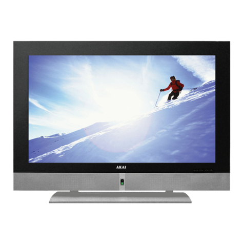
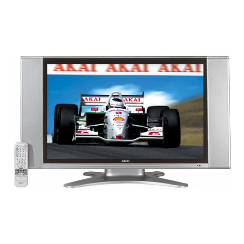
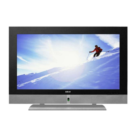
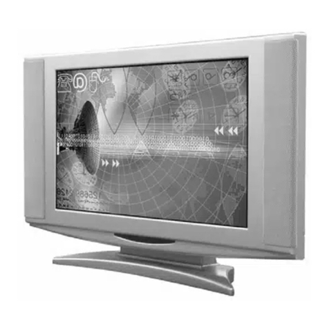
Akai LCT42Z6TM User manual

AKAI
SERVICE MANUAL
Model: LCT42Z6TM
1. Safety Instructions………………...………………………………………………….1~2
2. Trouble Shooting manual of LCD…………………………………………………….3~4
3. Product Specification………………………………………………………………….5~7
4. Block Diagram….…………………………………………………………………….8~9
5. Circuit diagram……………………………………………………………………….10~17
6. Basic Operation & Circuit Description………………………………………………18~20
7. Main IC Information…………………………………………………………………21~39
8. Panel Information……………………………………………………………………40~68
9. Explored View………………………………………………………………………69
10. Spare Pare List………………………………………………………………………70~72
11. Software Upgrade……………………………………………………………………73~75
This manual is the latest at the time of printing, and does not
include the modification which may be made after the printing,
by the constant improvement of product.

-2-
I. SafetyInstructions
PRECAUTIONSDURINGSERVICING
1. Inaddition tosafety,otherpartsand assembliesare
specified forconformancewithsuchregulationsas
thoseapplying tospuriousradiation.Thesemust
alsobe replaced onlywithspecified replacements.
Examples:RFconverters,tunerunits,antenna
selection switches,RFcables,noise-blocking
capacitors,noise-blocking filters,etc.
2.Usespecified internalWiring.Noteespecially:
1)Wirescovered withPVCtubing
2)Doubleinsulated wires
3)High voltage leads
3.Usespecified insulating materialsforhazardous
liveparts.Noteespecially:
1)Insulating Tape
2)PVCtubing
3)Spacers(insulating barriers)
4)Insulating sheetsfortransistors
5)Plasticscrewsforfixing microswitches
4.When replacing ACprimaryside components
(transformers,powercords,noiseblocking
capacitors,etc.),wrap endsofwiressecurelyabout
the terminalsbeforesoldering.
5.Makesurethatwiresdo notcontactheatgenerating
parts(heatsinks,oxide metalfilmresistors,fusible
resistors,etc.)
6.Check ifreplaced wiresdo notcontactsharplyedged
orpointed parts.
7.Makesurethatforeign objects(screws,solder
droplets,etc.)do notremaininside the set.
MAKEYOUR CONTRIBUTIONTOPROTECTTHE
ENVIRONMENT
Used batterieswiththe ISOsymbol
forrecycling aswell assmall
accumulators(rechargeablebatteries),mini-batteries
(cells)and starterbatteriesshouldnotbe thrown
intothe garbage can.
Pleaseleavethematan appropriatedepot.
SAFETYINSTRUCTION
The serviceshouldnotbe attempted byanyone
unfamiliarwiththe necessaryinstructionson this
monitor.The following arethe necessaryinstructions
tobe observed beforeservicing.
1.Anisolation transformershouldbe connected inthe
powerline between the receiverand the ACline
when aserviceisperformed on the primaryofthe
convertertransformerofthe set.
2.Complywithall caution and safetyrelated provided
on the back ofthe cabinet, inside the cabinet, on the
chassisorpicturetube.
3.Toavoidashock hazard,always discharge the
picturetube'sanode tothe chassisground before
removing the anode cap.
The lightning flashwitharrowhead symbol,
withinan equilateraltriangle,isintended toalert
the usertothe presenceofuninsulated “dangerous
voltage”withinthe product’ s enclosurethatmay
be ofsufficientmagnitude toconstitutearisk of
electricshock topersons.
The exclamation pointwithinan equilateral
triangleisintended toalertthe usertothe
presenceofimportantoperating and maintenance
(servicing)instructio nsinthe li terature
accompanying the appliance.
CAUTION:TOREDUCETHERISKOFELECTRIC
SHOCK,DONOTREMOVECOVER(ORBACK).NO
USER-SERVICEABLEPARTSINSIDE.REFER
SERVICINGTOQUALIFIEDSERVICEPERSONNEL
ONLY.
CAUTION
RISKOFELECTRICSHOCK
DONOTOPEN
1/75

PRODUCTSAFETYNOTICE
Manyelectricaland mechanicalpartsinthis
monitor havespecialsafety-related characteristics.
Thesecharacteristics areofferpassed unnoticed by
visualspection and the protection afforded bythem
cannotnecessarilybe obtained byusing replacement
componentsratesforahighervoltage,wattage,etc.
The replacementpartswhichhavethesespecial
safetycharacteristics areidentified bymarks on
the schematicdiagramand on the partslist.
Beforereplacing anyofthesecomponents,read the
partslistinthismanualcarefully.The useof
substitutereplacementpartswhichdo nothavethe
samesafetycharacteristics asspecified inthe parts
listmaycreateshock,fire,X-RAY RADIATIONor
otherhazards.
Good earthground
suchasthe water
pipe,conductor,
etc.
Placethisprobe
on eachex-
posed metallic
part
ACVOLTMETER
ACLeakage CurrentCheck
4.Completelydischarge the high potentialvoltage ofthe
picturetube beforehandling.The picturetube isa
vacuumand ifbroken,the glass will explode.
5.When replacing aMAINPCBinthe cabinet, always
be certainthatall protectiveareinstalled properly
suchascontrolknobs,adjustmentcoversorshields,
barriers,isolation resistornetworks etc.
6.When servicing isrequired,observethe originallead
dressing.Extraprecaution shouldbe given toassure
correctlead dressing inthe high voltage area.
7.Keep wiresawayfromhigh voltage orhigh tempera
turecomponents.
8.Beforereturning the settothe customer,always
perform an ACleakage currentcheck on the exposed
metallicpartsofthe cabinet, suchasantennas,
terminals,screwheads,metaloverlay,controlshafts,
etc., tobe surethe setissafetooperatewithout
dangerofelectricalshock.Plug the ACline cord
directlytothe ACoutlet(do notusealine isolation
transformerduring thischeck).Usean ACvoltmeter
having 5Kohmsvoltsensitivityormoreinthe
following manner.
Connecta1.5Kohm10 watt resistorparalleled bya
0.15µFACtype capacitor,between agood earth
ground (waterpipe,conductoretc.,)and the exposed
metallicparts,one atatime.
Measurethe ACvoltage across the combination of
the 1.5Kohmresistorand 0.15 uFcapacitor.Reverse
the ACplug atthe ACoutletand repeatthe AC
voltage measurementsforeachexposed metallic
part.
The measured voltage mustnotexceed 0.3VRMS.
Thiscorrespondsto0.5mAAC.Anyvalue exceeding
thislimitconstitutesapotentialshock hazardand
mustbe corrected immediately.
The resistancemeasurementshouldbe done
between accessibleexposed metalpartsand power
cordplug prongswiththe powerswitch"ON".The
resistanceshouldbe morethan 6Mohms.
2/75

in each of the corners of the screen.
Procedure Instructions 280 C-301, C-302, C-320 and C-323/ surface mounted 100UF 35 VOLTS.
"shipping" section of the claim for proper processing.
No image or badly distorted image with horizontal and/or vertical lines static lines.
Symptom may have four boxes
There are 5 capacitors on the main PCB that have been identified as the primary
cause of this symptom.
Replace the capacitors in location #'s on the Main PCB -
C-280 C-301, C-302, C-320 and C-323/ surfacemounted 100UF 35 VOLTS. For
warranty claims, list work as RPRE on the claim and list the cost of the caps to the

1.Do not power on .
1.1 Please check AC cable if connect to AC plug.
Is true the connector don’t connect toAC plug. Please connect it.
1.2 Please check AC cable if connect to AC power.
Is true the AC cable don’t connect toAC power. Please connect it.
1.3 Please check power board of fuse if broken.
If the F1 fuse is broken, Please pull out the AC cable from AC power. Please check AC L
power and AC N ground by multimeter, The read number is infinite, the fuse is broke. then
look up power board if not burn out place. Is true it. Please change power board or be changed
power board.
2. The power on switch of green extinguish.
2.1 The power of led(indicator light) is red light, To touch power on key when indicator light
wink.
Is true that the power DC output have somewhere short circuit.
3.The power is normal work ,but don’t backlight.
3.1 The indicator light work normal (green light ).
Please refer to attached sheet A circuit diagram.
3.2 Please check backlight of connector if not it direction is wrong or the connector of wire
compositor direction is wrong.
3.3 To check connector panel of voltage is +24v. It’s true. Then to check of the first pin if it
3/75

have +5V voltage, It’s true, than to check power board of +24v voltage, It’s true. The
panel of backlight board is fail. The change panel of backlight board.
Please refer to attached sheet B Panel of datasheet.
4.The screen don’t have picture But have backlight.
4.1 To check to panel of voltage , to check Main Board IC N031 the 5 pin of voltage is +12v.
If not, check the +12v power.
Please refer to attached sheet A circuit diagram.
5.The remote control don’t be control.
5.1 The check batteries of remote control if it run out of .
5.2 To check main board of connecter X014 of wire connect fastness and the connecter of
wire open.
Please refer to attached sheet A circuit diagram.
6.The sound don’t output.
6.1 To check main board +24v voltage of connector X032, It’s true not +24v voltage. Then
to to check power main +24v fail .
Please refer to attached sheet A circuit diagram.
4/75

Product Specification
Product Model: LCT42Z6TM
Screen Size: 42” diagonal
Screen Area: 930.24mm(H) x 531.26mm(V)
Aspect Ratio: 16:9
External Size:
1067.3mm(W) x 781.2mm(H) x 275.0mm(D) (with Stand)
1
067.3mm(W) x 732.3mm(H) x 117.0mm(D) (w/o Stand)
Net Weight:27.5kg (with Stand)
Resolution: 1920 (H) x 1080 (V) pixels (Each pixel has R/G/B 3
color cells)
Pixel Dot Pitch: 0.4845mm(H) x 0.4845mm(V)
Color: 16.7 millions of colors (R/G/B each 256 scales)
Gray Scale: 256 (R/G/B each 8-bit)
Brightness(Peak Value): 500cd/m2
Contrast(Dark Room): 800:1
Color System: PAL, NTSC
Sound Effect: Acoustic Cinema Enhancement
Power Supply: AC 120V, 60 Hz
Power Consumption: 300W
Input/Output Terminal: HDMI (Ver1.1) connector x 1
VGA ( D-Sub 15 Pin ) x 1
Component Video - YPbPr x 2 RCA Terminals
Video Input RCA Terminals x 1
S-Video Input Mini Din 4 Pin Terminal x 1
1 set of Stereo Audio Output Terminals (RCA, L&R)
Stereo, Audio x 5
5/75

Support the Signal Mode
A. D-Sub Mode (VGA)
B. HDTV Mode (YPbPr)
Resolution
Horizontal
Frequency
(KHz)
Vertical
Frequency
(Hz)
640 x 480 31.50 60.00
800 x 600 35.16 56.25
37.90 60.32
1024 x 768 48.40 60.00
1280 x 1024 64.00 60.01
Resolution
Horizontal
Frequency
(KHz)
Vertical
Frequency
(Hz)
480i 15.734 59.94
480p(720x480) 31.468 59.94
720p(1280x720)
37.50 50.00
45.00 60.00
1080i(1920x1080) 33.75 60.00
1080P 68.00 60.00
- When the signal received by the Display exceeds the allowed range, a warning
message shall appear on the screen.
- You can confirm the input signal format from the on-screen.
Resolution
Horizontal
Frequency
(KHz)
Vertical
Frequency
(Hz)
480p 31.468 59.94
720p
37.50 50.00
45.00 60.00
1080i 28.125 50.00
33.75 60.00
1080P 68.00 60.00
C. HDMI Mode
6/75

Remote Control
Standby( ): Press this button to turn off
to standby and turn on from standby.
Mute( ): Press this button to quiet the
sound system. Press again to reactivate
the sound system.
Number buttons: Use these buttons
to enter the password.
Source: Press this button and use
▲ / ▼
button to select the signal sources.
VIDEO, S-VIDEO,
YPbPr 1
,
YPbPr 2,
VGA or HDMI
.
Sleep: Press this button to
select
the
sleep
time, such as “15 Min, 30 Min,
45Min, 60 Min, 90 Min,
120 Min or Off”.
VOL +/- : Press these buttons to
increase
or decrease the volume
.
P. Mode : Press the button to select
different
picture effect, such as “Nature,
Bright,
User or Soft”.
System: Press this button to select the
color system, such as “PAL, NTSC or
AUTO”.
(Only for VIDEO and S-VIDEO)
Enter : Press to enter or confirm.
◄ / ► : They are used as ◄ / ► buttons
in the OSD Menu screen. ► also has
enter function.
▲ / ▼ : They are used as ▲ / ▼ buttons
in the OSD Menu screen.
Exit: Press this button to exit the OSD Menu.
Menu: Press this button to pop up the OSD Menu
and press it again to exit the OSD Menu.
V-Chip: Press this button to enter the V-Chip Function. (Only for VIDEO and
S-VIDEO)
Freeze: Press this button to hold on the screen. Press again to normal.
C/C: Press this button to change the CC mode. (Only for VIDEO and S-VIDEO
)
Display: Press the button to display the source information.
S. Mode: Press the button to select different sound effect, such as “Normal,
News, Music or User”.
P. Size: Press this button, the picture will change according
to
Full, Zoom,
Letter Box or 4:3. (Inactive for VGA)
7/75

MST9U89AL
HY5DU281622FT
DDR128M
PS25LV010A
flash
S-Video
Video
Switch
4052
Switch
PI5V330
Audio
S-Video
Audio
Video
Audio
YPbPr1
YPbPr2
YPbPr1
Audio
YPbPr2
Audio
HDMI
VGA
E PROM
24C32
2
Panel
LVDS
Operation
Amplifier
4558R
Audio
Amplifier
R251502NP
Speaker
Operation
Amplifier
4558R
Audio
Out
Audio
DVI/VGA
8/75

Parts position
Key Pad
Speaker
Power Board
Speaker
Main Board IR Board
9/75

10/75

11/75

12/75

13/75

14/75

15/75

16/75

17/75

Basic Operations & Circuit Description
MODULE
There are 1 pcs panel and 5 pcs PCB including 3 pcs Extension PCB, 1 pcs Timming controller board and 1 pcs Back Light board
in the Module.
SET
There are 3pcs PCBs including 1 pcs, 1 pcs keypad board, 1 pcs Remote Control Receiver board, 1 pcs Main(Video)board.
18/75
Other manuals for LCT42Z6TM
1
Table of contents
Other Akai Monitor manuals

Akai
Akai PDP5090 User manual

Akai
Akai PDP4216M User manual

Akai
Akai PDP4273MN User manual

Akai
Akai PDP4247 User manual

Akai
Akai PDP5073TM User manual

Akai
Akai PDP4290 User manual

Akai
Akai PDP4216M User manual

Akai
Akai LMH27CJSA User manual

Akai
Akai LMH27CJSA User manual

Akai
Akai PDP4206EM - 42" Plasma EDTV User manual