2. Specifications
2.1 Specification :
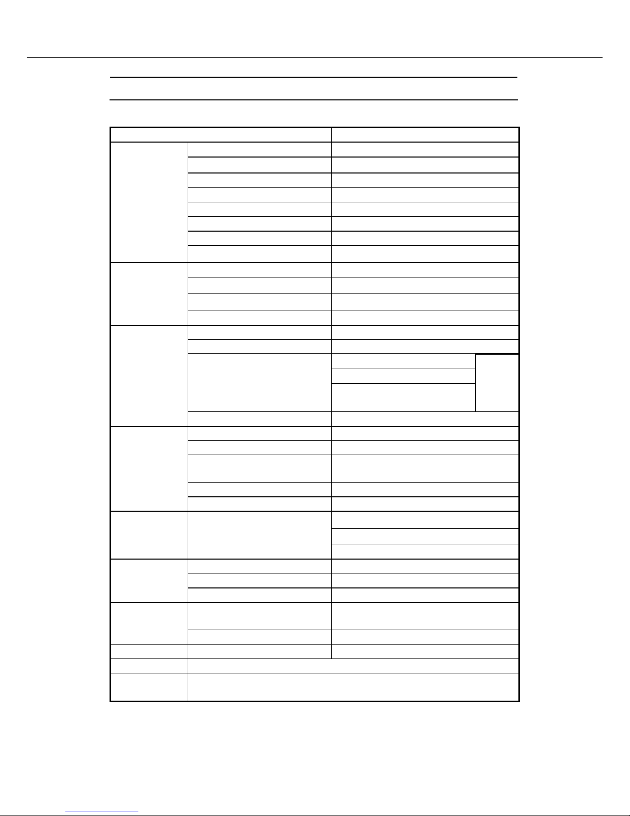
ITEMS SPECIFICATION
Screen size 17” Wide TFT-LCD Panel (Fujitsu)
Aspect Ratio 16:9
Resolution 1280 x 768 (Wide-XGA)
Contrast Ratio 400 : 1 (Typical)
Brightness 400 cd/m² (Typical)
Viewing Angle 160° (Hor.) / 160° (Vert.)
Response Time : Ton / Toff 15ms / 10ms
Display
OSD Language English, French, German, Spanish, Italian
TV Standard (CCIR) B/G, D/K, I and L/L’ (Multi-Europe)
Color System PAL / SECAM
Sound System NICAM / A2 (IGR)
TV Function
Teletext 10 Pages (FLOF / TOP )
Color System PAL / SECAM / NTSC
AV1 (In / Out) 21-pin SCART (RGB / Video) x 1
Video (Composite) x 1
S-Video x1
AV2 (In)
Component (YPbPr, YCbCr) x 1
( DTV system : 625p)
Audio
L/R x 1
Video I/O
AV3 (Out) Video (Composite) TV only x 1
Signal I/P Analog : D-Sub 15 pin (detachable cable)
PnP compatibility DDC / 2B
I/P Frequency Analog: FH: 31kHz to 60kHz
F
v: 56Hz to 75Hz
Recommended Analog: 1024x768 (60Hz)
PC I/P
DTV ready (via D-sub 15pin) DTV System : 625p
Speaker (Built-in) : 3.5W+3.5W (rms)
Headphone Mini-jack for stereo (3.5 mm)
Audio O/P Audio O/P: L/R
Line Out (RCA L/R)
PIP under PC mode Yes
A.P.S. , Child-Lock Yes
Other Functions
VESA Panel Wall Mounting Holes 100mm x 100mm
Power Supply
DC 12V / 5A (external AC adapter)
AC 100V~240V, 50/60Hz
Power
Power Consumption < 60W
Panel Tilt Forwards/ Backwards /Rotation -5°/ +15° / ±180°
Weight (net) 6.5 Kg (Without Accessories)
Accessories Remote Control, Batteries x 2 , AC adapter, AC cord, 15 Pin D-Sub Signal Cable ,
Cable Clamps , Operation Manual .
-3-