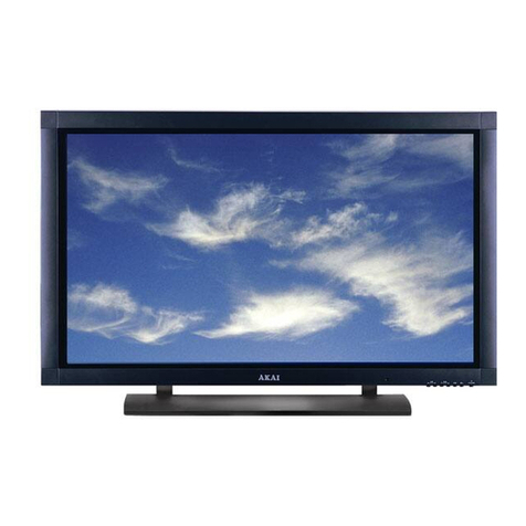
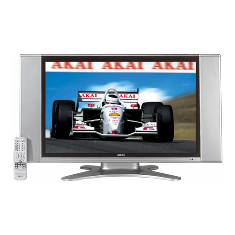
Akai pdp4295ed User manual

MODEL NO. : PDP4295ED
PDP4249G
PDV42S10
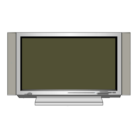
PLASMA MULTIMEDIAMONITOR
SERVICEMANUAL
AKAI
All manuals and user guides at all-guides.com
all-guides.com

CONTENTS
1. IMPORTANT INFORMATION
2. GENERAL INFORMATION
3. SAFETY PRECAUTIONS
4. SPECIFICATION
5. PERIPHERAL EQUIPMENT CONNECTING
6. CIRCUIT DESCRIPTION
. DC POWER SUPPLY
. VIDEO
7. CHAPTER BLOCK DIAGRAM
. BLOCK DIAGRAM
. AC FILTER
. EMI BOARD
. DC POWER BOARD
. VIDEO BOARD
. AMPLIFIER BOARD
. TUNER BOARD
. ASSEMBLY DRAWING
8. TROUBLE SHOOTING FLOW CHART
. ASSEMBLY CHART
. SET TEST CHART
. VIDEO DISPLAY CHART
9. CLEANING AND MAINTENANCE HANDY TIPS
DISPLAY BOARD
Page
1
2
3
4
5
6
7
8
9
10
11
12
13
14
15
16
17
18
19
1
All manuals and user guides at all-guides.com

2
IMPORTANTINFORMATION
WARNING
SHOCK !DANGEROUS!
DO NOT OPEN REAR COVER. !
WARNING:1.ThisisaClassAand Class B product. In a domestic environment this
productmaycauseradiointerferenceinwhichcasethe user may be
requiredtotakeadequatemeasures.
2.TOREDUCETHERISKOFFIREANDELECTRIC SHOCK, DO NOT
EXPOSETHISPRODUCTTORAINORMOISTURE.
IMPORTANT
Thislightningflashwitharrowheadsymbol,withinanequilateraltriangle,
isintendedtoalerttheusertothepresenceofuninsulated
"dangerousvoltage"withintheproduct'senclosurethatmay be of sufficient
magnitudetoconstituteariskofelectricshock.
!Theexclamationpointwithinanequilateraltriangleisintended to alert
theusertothepresenceofimportantoperatingandmaintenance
(servicing)instructionsintheliteratureaccompanyingtheappliance.
All manuals and user guides at all-guides.com

ANALOG VGA
INPUT
DVI
INPUT
AC 100 240 V
INPUT
POWER SWITCH
ON OFF
RS-232
INPUT
Menu
LED
Power
SelectDown
SelectUp
Enter
Volume+
Volume-
AUDIO
INPUT
Y Pb(Cb) Pr(Cr)
S-VIDEO
INPUT
AUDIO
OUTPUT S-V/DVI AV/VGA AV
COM2 COM1
COMPONENT
ANT/CABLE IN
SPEAKER R
SPEAKER L
3
FrontView
RearView
GENERALINFORMATION
IMPORTANT:
Whenthesetisswitchedon,donotshiftormovethesetaround.
Sometimesitmaydevelopanunevennessincolourinsomeparts
ofthescreen.Thiscanbeeliminatedbyswitchingoffthesetwith
themainpowerbutton(rearsite)andwaitfor10minutesbefore
switchingonagain.Ifthesituationremains,callforService.
All manuals and user guides at all-guides.com

.
4
SAFETYPRECAUTIONS
.Theplasmapanel has been built using extremely precise and
sophisticatedtechnologies;More than 99.99% of its pixels are
effective.Aminutenumberofpixels are missing or constantly lit.
.Donotdisplaythesame picture(pattem)for a long period of time
(Don'texceed20min.).This may cause images remain.
.Nofurthernoticewillbeprovidedifthe specification and design
subjectshavebeenchanged.
.Toreleasethe battery of remote controller after long time
replacement(over1month)andtoavoidmaking
destructionofremotecontrollerbyliquid.
Pleasereadthefollowingdirectioncarefullybeforeusingthismachine.
.Readeachdirection carefully, and retain for future reference.
.Pleasekeepthe manual well.
.Pleasefollowtheinformationtooperate this machine.
.Cleanthemachine with a slightly damp soft cloth. Do not use spray detergent
andabrasivesolvent.It can damage the machine screen coating layer.
.Placethemachineon a solid base to avoid dropping and danger.
.Forgoodventilationofthemachine, please do not place the machine on
surfacessuchas bed, sofa, or rug.
.Beforeoperatingthemachine, make sure that the operating voltage of your
machineisidenticalwiththat of your local power supply, if there is any
unclear,pleasecontact with sales dealer.
.Useonlytheaccessory power cord designed for this product to prevent shock.
.Donotputanythingunderthepower cord to avoid tramping.
.Ifusingthesamepower source with other equipments, please make
surethetotalcurrentdoes not over 15A.
.Neverattempttorepaira defection of the machine by yourself. Always
consultaskilledmachine service personnel.
.Whenthefollowingsituationshappen, please contact
qualifiedengineer.
A.Thepowercordorthe power socket has damages.
B.Ifanyliquidorsolidobject fall into the machine through the
ventilationholes.
C.Exposethemachine to rain or excessive moisture.
D.Thefunctiondoesnot follow the user manual.
E.Themachinehas ever been dropped or the glass has been broken.
F.Thefunctionofmachinehas clear changes.
.Whan none operation the product storagr is suggested not
.exced max of 6 months.If it is the exceed the suggested
.storage period,the product should be activated for 24 hrs.
.To ensure the quality of the product.
All manuals and user guides at all-guides.com

(1)input signal :S-Video、composite、Component、Analog RGB、DVI、NTSC RF
(2)video signal:0.7Vp-p
(3)scan frequency:Analog RGB auto-sync H from 30 to 80KHz
V from 60 to 85Hz
DVI auto-sync H from 30 to 80KHz
V from 60 to 85Hz
Component:480i、480P、576i、576P、720P、1080i
Composite:Video sync
S-Video:Y-C separate sync
TV : NTSC 60Hz
(4)up data terminal:RS-232 DB-9 PIN
(5)Power supply:AC100-240 Volts universal
(6)Power consumption:330W (Full White Pattern)
(8)Signal cable:15PIN D-SUB、DVI-D、S-Video、RCA Jack、Speaker Jack、
AV Shielded Video cable
(9)OSD controls:
Video a section:
<1>Picture: H/V Position、Brightness、Contrast、Sharpness、
Color、Tint、Frequency、Phase、Auto Image
<2>Advanced: Gamma、Color Temperature、Color Management.
<3>Source: Analog RGB、DVI、Component1、Component2、
S-Video、Video、TV
<4>Function: Scaling、Zoom、White Pattern、Close Caption、
[PIP]Source、[PIP]Size、[PIP]H/V-Position
<5>Utility: Language、Video Standard、DPMS、
[OSD]H/V-Position、[OSD]Time Out、
Picture Scrolling、Load Factory
<6>TV: Tuner Select、Channel、MTS、Channel Scan、V-chip
Sound a section:
Volume、Treble、Bass、4 steps BBE Selects、SRS virtual Surround、
MTS STEREO Decoder
5
SPECIFICATION
All manuals and user guides at all-guides.com
all-guides.com

AnalogRGB Output
PC
DVD S-Video Output
DVD Video Output
DVD Y Pb(Cb) Pr (Cr) Output
DVD
VCR
Amplifier
DVD Audio Output
AudioInput
RS-232
INPUT
AC 90 240 V
INPUT
Antenna/Cable
AV
AUDIO
INPUT
S-V/DVI AV/VGA
COM2 COM1
AUDIO
OUTPUT RS-232
INPUT
Y Pb(Cb) Pr(Cr)
S-VIDEO
INPUT
COMPONENT
ANT/CABLE IN
ANALOG
VGA IN
DVI
INPUT
DVI-DOutput
POWER SWITCH
ON OFF
6
PERIPHERALEQUIPMENTCONNECTING
All manuals and user guides at all-guides.com

7
CIRCUITDESCRIPTION
1.DCPOWERSUPPLY
ThisistheDCpowersupply inside the PDP, in which Cn1 connected
withalternatingcurrent(AC)throughinductancefilter(L1),
rectificationbridge(BD1)IC,transformer(T1), D3, D4, to CN2 output
with5Vand12Vdirectcurrent.The range of the AC output is from 90V to
264Vandfrequencyisfrom50Hzto60Hz. The largest detrition
rateis40W
All manuals and user guides at all-guides.com

8
2.VIDEODISPLAYBOARD
ThisisthesignalinsidethePDPandaudiodevicedisposition.
1)ItcanreceivecompositesignalincludingR.G.B.H.V.contrast
signal,DVIdigitalsignal,AVcolordistinctionsignaland
S-Video.....etc.
R.G.B.H.V.&YPbPr:The signalisinputfrom(15PIN)J1&J1
toU6toperformcontrastsignal,then
transformtodigitalsignalandentertoU29,
thesignalispassertoU33fortheoutputof
visualsignal.
DVI : DigitalsignalisinputfromP1the managedbyU6andpassed
toU29,thesignalispassedtoU33fortheoutputofvisual
signaloutput.
AV&TV: AV&TV signal entersfromJ12&JP18toU46 to
performsignal,thentransformtoU47todecode perform
signal,then transformtoU49todeinterlaceperformsignal
andentertoU29,thesignalpassedtoU33fortheoutput
ofvisualsignal.
S-Video:S-VideosignalinputfromJ12to U47todecodeperform
signal,thentransformtoU49todeinterlacepreform
signalandentertoU29,thesignalpassedtoU33forthe
outputofvisualsignal.
toU5forvisualproductionandafterdeposition,itwillpass
toU7forsignalcompensationandtoU9forvisualsignal
depositionoutput.
2)AudioisinputfromJ3,J8andfromU62toperform
pre-production.Then,theaudiosignalispassedtoU61SRSprocess
forthesignaloutputbyJ4andJ9.
3)WhenaudiosignaltheJ4passedtoAmplifyforthefinaloutput.
All manuals and user guides at all-guides.com

1. BLOCK DIAGRAM
9
AMPLIFIER
BOARD
VIDEO
BOARD
DC
POWER
EMI BOARD
PANEL
AC IN
TUNER
BOARD
CHAPTERBLOCKDIAGRAM
All manuals and user guides at all-guides.com

2. AC FILTER
1. AC INPUT TO C1
2. C2 TO EMI BOARD J1
10
All manuals and user guides at all-guides.com
all-guides.com

3. EMI BOARD
1. AC FILTER C2 TO J1
2. J2 TO PANEL & DC POWER CN1
11
All manuals and user guides at all-guides.com

NC 2
CN1
1. EMI FILTER J2 TO CN1
2: CN2 TO MONITOR BOARD
4. DC POWER BOARD
12
All manuals and user guides at all-guides.com

5. VIDEO DISPLAY BOARD
13
1.J17 TO PANEL
2.JP17, JP3 TO TUNER BOARD
3.J25 TO DC POWER
4.JP11 TO KEYPAD
5.J4 TO AMPLIFIER BOARD
6.J5 TO RS232 CONNECTOR
J17 J4
J5
Jp18Jp1
J25
Jp11
Jp17Jp3
All manuals and user guides at all-guides.com

6. AMPLIFIER BOARD
1. VIDEO BOARD J4 TO JP1
2. DC POWER BOARD CN2 TO JP2
3. JP3 TO RIGHT SPEAKER JACK
4. JP4 TO LEFT SPEAKER JACK
14
All manuals and user guides at all-guides.com

7. TUNER BOARD
15
1. VIDEO BOARD JP17 TO JP1
2. VIDEO BOARD JP3 TO J1
3. CABLE TO CABLE INPUT
J1 Jp1
CABLE IN
All manuals and user guides at all-guides.com
all-guides.com

8. ASSEMBLY DRAWING
16
All manuals and user guides at all-guides.com

1. ASSEMBLY CHART
17
YES
YES
YES
NO
NO
NO
TROUBLESHOOTINGFLOWCHART
All manuals and user guides at all-guides.com

2. SET TEST CHART
18
VIDEO DISPLAY
I/P
FIX
WHITE PATTEN
TEST
YES
NO
CHECK
1. SPEAKER
2. VIDEO BOARD
3. AUDIO CIRCUIT
NO
AUDIO VOLUME
I/P
YES
PANEL DISPLAY
YES
CHECK
1. AC INPUT
2. DC POWER
3. VIDEO BOARD
NO
NO
END
All manuals and user guides at all-guides.com

3. VIDEO DISPLAY CHART
19
RGB I/O
DVI I/O
CHECK
1. CABLE
2. SIGNAL
3. U7, U9, U61, U62
YES
NO
CHECK
1. CABLE
2. SIGNAL
3. U46, U47, U49
NO
AV I/O
YES
AUDIO I/O
YES
CHECK
1.
2.
3. U6
CABLE
SIGNAL NO
NO
END
All manuals and user guides at all-guides.com
Other manuals for pdp4295ed
1
This manual suits for next models
2
Table of contents
Other Akai Monitor manuals

Akai
Akai HPL5025M User manual

Akai
Akai SPL4225 User manual

Akai
Akai LCT42Z6TM User manual

Akai
Akai LCT2785TA User manual

Akai
Akai PDP4206EM - 42" Plasma EDTV User manual

Akai
Akai LMH27CJSA User manual

Akai
Akai PDP4249G User manual

Akai
Akai PDP4247 User manual

Akai
Akai PDP4216M User manual

Akai
Akai PDP4290 User manual