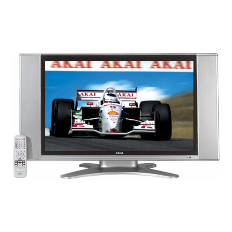
Akai PDP4225M User manual

KA WA ELECTRONIC RESEARCH & DEVELOPMENT CENTRE
Service Manual
Reference No.
Revision
Date
Page
SM- PDP421DMIAl BS - 2
0
2 6.Jan.2£
P.l of 7$
In House Model No.
Customer Model No. : PDP421D
: PDP4225M
BOM No : PDP421DMIAIBS -A 2
Description : Service Manual for PDP4225M _FHP (A3)_USA
Prepared By:
Checked By:
Approved By
\ t)
Received By: MK Department
______
V v is '
DOC Rev
NO. The Latest Revision Details DATE
Initial Release 2 6-Jan-2Ç
4 Â
Electronic Engineer
Mechanical Engineer
Engineering Manager

SERVICE MANUAL
Model:
PDP4225M
Safety Precaution............................................................................................1-2
Technical Specifications..............................................................................3-10
Block Diagra .............................................................................................11-12
Circuit Diagra ........................................................................................... 13-28
Basic Operations & Circuit Description
.................................................
29-33
Main IC Specifications...............................................................................34-54
Panel Infor ation.......................................................................................55-67
Spare Part list.............................................................................................68-70
Exploded View.................................................................................................71
If You Forget Your V-CHIP Password
........................................................
72
Software Upgrade............................................................................................73
This manual is the latest at the time of printing, and does not
include the modification which may be made after the printing,
by the constant improvement of product.

Safety Precaution
ACAUTION
RISK OF ELE TRI SHO K
DO NOT OPEN
AUTION: TO REDU E THE RISK OF
ELE TRI SHO K, DO NOT REMOVE OVER
(OR BA K). NO USER-SERVI EABLE PARTS
INSIDE. REFER SERVI ING TO QUALIFIED
SERVI E PERSONNEL ONLY.
AThe lightning flash with arrowhead sy bol,
within an equilateral triangle, is intended to
alert the user to the presence of uninsulated
“dangerous voltage” within the product’s enclo
sure that ay be of sufficient agnitude to
constitute a risk of electric shock to persons.
The excla ation point within an equilateral
triangle is intended to alert the user to the
presence of i portant operating and
aintenance (servicing) instructions in the
literature acco panying the appliance.
PRE AUTIONS DURING
SERVI ING
1. In addition to safety, other parts and
asse blies are specified for confor ance with
such regulations as those applying to spurious
radiation. These ust also be replaced only
with specified replace ents.
Exa ples: RF converters, tuner units, antenna
selection switches, RF cables, noise-blocking
capacitors, noise-blocking filters, etc.
2. Use specified internal Wiring. Note especially:
1) Wires covered with PVC tubing
2) Double insulated wires
3) High voltage leads
3. Use specified insulating aterials for hazardous
live parts. Note especially:
1) Insulating Tape
2) PVC tubing
3) Spacers (insulating barriers)
4) Insulating sheets for transistors
5) Plastic screws for fixing icro switches
4. When replacing AC pri ary side co ponents
(transfor ers, power cords, noise blocking
capacitors, etc.), wrap ends of wires securely
about the ter inals before soldering.
5. Make sure that wires do not contact heat
generating parts (heat sinks, oxide etal fil
resistors, fusible resistors, etc.)
6. Check if replaced wires do not contact sharply
edged or pointed parts.
7. Make sure that foreign objects (screws, solder
droplets, etc.) do not re ain inside the set.
MAKE YOUR ONTRIBUTION
TO PROTE T THE
ENVIRONMENT
Used batteries with the ISO sy bol \5<9
for recycling as well as s all accu ulators
(rechargeable batteries), ini-batteries (cells) and
starter batteries should not be thrown into the
garbage can.
Please leave the at an appropriate depot.
WARNING:
Before servicing this TV receiver, read the
SAFETY INSTRUCTION and PRODUCT
SAFETY NOTICE.
SAFETY INSTRU TION
The service should not be atte pted by anyone
unfa iliar with the necessary instructions on this
apparatus. The following are the necessary
instructions to be observed before servicing.
1. An isolation transfor er should be connected in
the power line between the receiver and the
AC line when a service is perfor ed on the
pri ary of the converter transfor er of the set.
2. Co ply with all caution and safety related
provided on the back of the cabinet, inside the
cabinet, on the chassis or picture tube.
3. To avoid a shock hazard, always discharge the
picture tube's anode to the chassis ground
before re oving the anode cap.
4. Co pletely discharge the high potential voltage
of the picture tube before handling. The picture
tube is a vacuu and if broken, the glass will
explode.
1/73
5. When replacing a MAIN PCB in the cabinet,
always be certain that all protective are
installed properly such as control knobs,
adjust ent covers or shields, barriers, isolation
resistor networks etc.
6. When servicing is required, observe the original
lead dressing. Extra precaution should be given
to assure correct lead dressing in the high
voltage area.
7. Keep wires away fro high voltage or high
te pera ture co ponents.
8. Before returning the set to the custo er,
always perfor an AC leakage current check
on the exposed etallic parts of the cabinet,
such as antennas, ter inals, screwheads, etal
overlay, control shafts, etc., to be sure the set
is safe to operate without danger of electrical
shock. Plug the AC line cord directly to the
AC outlet (do not use a line isolation
transfor er during this check). Use an AC
volt eter having 5K oh s volt sensitivity or
ore in the following anner.
Connect a 1.5K oh 10 watt resistor paralleled
by a 0.15^F AC type capacitor, between a
good earth ground (water pipe, conductor etc.,)
and the exposed etallic parts, one at a ti e.
Measure the AC voltage across the co bination
of the 1.5K oh resistor and 0.15 uF
capacitor. Reverse the AC plug at the AC
outlet and repeat the AC voltage easure ents
for each exposed etallic part.
The easured voltage ust not exceed 0.3V
RMS.
This corresponds to 0.5 A AC. Any value
exceeding this li it constitutes a potential
shock hazard and ust be corrected
i ediately.
The resistance easure ent should be done
between accessible exposed etal parts and
power cord plug prongs with the power switch
"ON". The resistance should be ore than
6M oh s. AC VOLTMETER
PRODU T SAFETY NOTI E
Many electrical and echanical parts in this
apparatus have special safety-related
characteristics.
These characteristics are offer passed
unnoticed by visual spection and the protection
afforded by the cannot necessarily be obtained
by using replace ent co ponents rates for a
higher voltage, wattage, etc.
The replace ent parts which have these
special safety characteristics are identified by A
arks on the sche atic diagra and on the parts
list. Before replacing any of these co ponents,
read the parts list in this anual carefully. The
use of substitute replace ent parts which do not
have the sa e safety characteristics as specified
in the parts list ay create shock, fire, or other
hazards.
9. Must be sure that the ground wire of the AC
inlet is connected with the ground of the
apparatus properly.
Good earth ground
such as the water
- pipe, conductor,
etc.
1500 ohmi, lOwatt
Place this probe
on each exposed
metallic part
AC Leakage Current Check
2/73

T e c h n ic a l S p e c if ic a t io n s PDP4225M
1. S ta n d a rd T es t o n d itio n s
All tests shall be perfor ed under the following conditions, unless otherwise specified.
1.1 A bient light : 150ux (When easuring IB, the a bient lu inance
= 0.1Cd/ 2)
1.2 Viewing distance : 50c in front of PDP
1.3 War up ti e : 30 inutes
1.4 PDP Panel facing : no restricted
1.5 Measuring Equip ent : PC, Chro a 2225 signal generator (with Chro a digital
additional card) or equivalent, Minolta CA100 photo eter
1.6 Magnetic field : no restricted
1.7 Control settings : Brightness, Contrast, Tint, Color set at Center(50)
1.8 Power input : 100~120Vac 60Hz
1.9 A bient te perature : 20°C ± 5°C (68°F ± 9°F)
1.10 Display ode : Resolution 1024 (H) x 1024 (V) Pixels
1.11 Other conditions
1.11.1 With i age sticking protection of PDP odule, the lu inance will descend
by ti e on a sa e still screen and rapidly go down in 5 inutes. When
easuring the color tracking and lu inance of a sa e still screen, be sure t
o acco plish the easure ent in one inute to ensure its accuracy.
1.11.2 Due to the structure of PDP, the extra-high-bright sa e screen should not
hold over 5 inutes for fear of branding on the panel.
3/73

T e c h n ic a l S p e c if ic a t io n s PDP4225M
E L E T R I A L H A R A T E R IS T I S
2. P o w e r In p u t
2.1 Voltage
2.2 Input Current
2.3 Maxi u Inrush Current
Test condition
2.4 Frequency
2.5 Power Consu ption
Test condition
2.6 Power Factor
2.7 Withstanding voltage
3. D is p la y
3.1 Screen Size
3.2 Aspect Ratio
3.3 Pixel Resolution
3.4 Peak Brightness
3.5 Contrast Ratio (Dark roo )
3.6 Viewing Angle
3.7 OSD language
4. S ig n al
4.1 AV & Graphic input
4.1.1 Co posite signal
4.1.2 Y,C Signal
4.1.3 Co ponent signal
4.1.4 Graphic I/P
4.1.5EDID co patibility
4.1.6 I/P frequency
100 ~120VAC 60Hz
5.0 /2.5A
<30 A (FOR AC110V ONLY)
Measured when switched off for at least 20 ins
60Hz(±3Hz)
330W Typical
full white display with axi u brightness and
contrast
Meets I EC 1000-3-2
1.5kVac or 2.2kVdc for 1 sec
42” Plas a display
16:9
852x480
1400 cd/ 2 (Typical, Panel only)
3000:1 (Ratio, Typical, in a dark roo , Panel only)
Over 160°
English, French, Spanish.
AV
S-Video
YPbPr, HDMI,VGA co patible
Analog: D-sub 15pin detachable cable
Digital:HDMI
DDC 1.3
fH: 31.5kHz to 60kHz/fV: 56.25Hz to 75Hz(1024x768
reco ended)
4/73

T e c h n ic a l S p e c if ic a tio n s PDP4225M
4.2 Audio input
4.3 Audio output
VGA(D-Sub 15 Pin Type) xi
D-Sub 9 Pin (RS-232 Input) x 1
HDMI (Ver. 1.1) connector x 1
S-Video (Mini Din 4 Pin) x 1
Video Input (RCA Type) x 1
YPbPrx 2
Stereo, Audio x 6
Audio&Video Output (RCA Type) x 1, SPDIF(Optical) x 1
PIP/PBP, Picture size, Picture Still, Sound ode,Last
e ory, Ti er
5. E n v iro n m e n t
5.1 Operating environ ent
5.1.1 Te perature :
5.1.2 Relative hu idity:
5.2 Storage and Transport
5.2.1 Te perature :
5.2.2 Relative hu idity:
6. P an el h a ra c te ris tic s
5° to 33°C
20% to 85%(non-condensing)
-20°C to 60°C(-4° to 140°F)
5% to 95%
6.1 Type
6.2 Size
6.3 Aspect ratio
6.4 Viewing angle
6.5 Resolution
6.6 Weight
6.7 Color
6.8 Contrast
6.9 Peak brightness
FHP(A3)
42”,932.94 (W)X532.80 (H)
(W/Ostand)
16:9
Over 160°
1024X1024
39.2kg (Net)
16.7 illions of colors (R/G/B each 256 scales)
Average 60:1 (In a bright roo with 150Lux at center)
Typical 10000:1 (In a dark roo 1/100 White Window
pattern at center).
Typical 1500cd/ 2 (1/25 White Window)
6.10 Color Coordinate Unifor ity :
Test Pattern :
Contrast; Brightness and Color control at nor al
setting
Full white pattern
Average of point A,B,C,D and E +/- 0.01
5/73

T e c h n ic a l S p e c if ic a t io n s PDP4225M
6.11 Color te perature Contrast at center (50); Brightness center (50);
Color te perature set at Natural
x=0.285±0.02
y=0.290±0.02
6.12 Cell Defect Specifications
Subject to Panel supplier specification as appends.
7. F ro nt P a n e l o n tro l B utto n
7.1 SEL. Up / Down Button
VOL. Left/Right Button
MENU Button
SOURCE Button
Select the Up/Down ite in OSD enu.
Push the key to increase the volu e left or right.
When selecting the adjusting ite in OSD enu
increase or decrease the data-bar.
Display or Exit the OSD enu.
Press this button and use up/down button to sellect
the signal sources. AV, S-Video, YPbPr 1,YPbPr 2,
VGA or HDMI.
7.2 STANDBY Button Switch on ain power, or switch off to enter power
Saving odes.
7.3 Main Power Switch Turn on or off the unit.
8. O S D F u nctio n
8.1 Picture : Brightness; Contrast; Saturation; Peaking; Phase; Sharpness; Frequency;
Picture Mode (Nor al, Bright, Cine a, User);
Color Te p (War , Nor al, Cool); etc.
8.2 Window : I age Size (Fill All, Force 4:3, Letter Box, Wide, Ana orphic, etc);
H Position; V Position; H Resolution; Freeze Window (Off, On)
8.3 Audio : Balance; Audio Mode (BBE, Cine a, Music, News, User)
(Internal, External); aVc (Off, On)
Equalizer (120Hz, 500Hz, 1.2kHz, 3kHz, 12kHz)
8.4 Options : Osd Ti eout (5 Sec, 15 Sec, 60 Sec); Menu Background (Opaque,
Translucent); Language(English, French, Spanish); Default Setting;
Close Caption Mode; Close Caption; Content Blocking; Ti er
8.5 Layout : Full Screen; PIP; Split Screen
6/73

Technical Specifications PDP42M
9. Agency Approvals
Safety : UL, FCC, FDA
E issions : UL, FCC, FDA
10. Reliability
MTBF : 20,000 hours(Use oving picture signal at 25°C a bient)
11. Accessories
User anual x1, Re ote control x1, Stand x 1, Battery x 2, AC Cable x 1
12. Remote ontrol
1 Standby(o): Press this button to turn off to
standby and turn on fro standby.
2 Mute(K): Press this button to quiet the sound
syste . Press again to reactivate the
sound syste .
3 P. Still: Press this button to hold on the
screen. Press again to nor al.
4 P. Size: When the input source is YPbPr 1,
YPbPr 2, VGA or HDMI, press this button,
the picture will change according to Fill All,
Force 4:3, Letter Box, Wide or Ana orphic.
When the input source is AV or S-Video, press
this button, the picture will change according to
Fill All, 4:3, Letter Box, Wide or Ana orphic.
5 S. Sele: Press this button to select the sound
output fro Main Window or Sub Window.
6 P. Mode : Press the button to select different
picture effect.
7 Time: Press this button to pop up the "Clock
Set” enu.
8 Sleep: Press this button to select the sleep
ti e.
9 Display: Press the button to display the
source infor ation.
10 Auto: The Display auto atically adjusts the
phase, vertical / horizontal position when
pressing this button in VGA ode.
11 Layout: Press this button to pop up Layout
enu.
12 / : Press this button to enter the Closed
Caption Function. (Only for AV or S-Video)
(Continued on next page)
7/73

Technical Specifications PDP4225M
13 V- hip: Press this button to enter the V-Chip
Function. (Only for AV or S-Video)
14 Number buttons: Use these buttons to enter
the password.
15 Swap: Press this button to switch the Main
window or Sub window pictures in PIP and
Split Screen.
16 F. White: Press this button to show a full
white picture.
17 PIP POS. : Press the button to select different
I age Position in PIP Mode.
18 PIP Size : Press the button to select different
I age Size in PIP Mode.
19 VOL +/- : Press these buttons to increase or
decrease the volu e.
20 Sound: Press the button to select different
sound effect.
21 W. Sele: Press this button to select the Main
Window or Sub Window.
22 Source: Press this button and use ▲ / ▼
button to select the signal sources. AV, S-Video,
YPbPr 1, YPbPr 2, VGA or HDMI.
23 PIP: Press this button to change different
Picture Mode.
24 Menu: Press this button to pop up the OSD
Menu and press it again to exit the OSD Menu.
25 OK : Press to enter or confir .
◄ / ► : They are used as ◄ / ► buttons in
the OSD Menu screen.
▲ / ▼ : They are used as ▲ / ▼ buttons in
the OSD Menu screen.
They also can be used for the selection of the
progra when the OSD Menu is not shown on
the screen, but only for the Model with Tuner.
14
® ® ®
J® ® ®
® ® ®
P. Still \ V- hlp / / Display
o o o o-
Sound Time PIP Size P. Size
O O 0 . 0 "
P. Mode Sleep F. White
OOOO-
8/73

Technical Specifications PDP4225M
13. Support the Signal Mode
13.1. VGA Mode, HDMI Mode or HDTV Mode (YPbPr 1 or YPbPr 2)
Mode Resolution Horizontal
Frequency
(kHz)
Vertical
Frequency
(Hz)
Dot Clock
Frequency
(MHz)
VGA Mode
640 x 480 31.50 60.00 25.18
800 x 600 37.90 60.32 40.00
1024x 768 48.40 60.00 65.00
1280x 1024 64.00 60.01 108.00
HDMI Mode 1080i 33.75 60.00 74.25
720p 45.00 60.00 74.25
480p 31.468 59.94 27.00
HDTV Mode
(YPbPr1/YPbPr2)
1080i 33.75 60.00 74.25
720p 45.00 60.00 74.25
480p 31.468 59.94 27.00
480i 15.734 59.94 13.50
13.2.PIP/PBP Screen Mode
Ite s VGA (Max.) HDMI/YPbPr1/YPbPr2
480p 720p 1080i
PIP
Main 1024 x 768 OK OK OK
Sub Large 1024 x 768 OK OK OK
Middle 1024 x 768 OK OK X
S all 1024 x 768 OK OK X
PBP Main 1024 x 768 OK OK OK
Sub 1024 x 768 OK OK OK
Note:
- “X” means out of range (can not show)
- When the signal received by the Display exceeds the allowed range, a warning
message shall appear on the screen
- You can confirm the input signal format from the on-screen
- VGA 1280 x 1024 Mode don’t recommend working in PIP/PBP Screen Mode
9/73

T e c h n ic a l S p e c if ic a t io n s PDP4225M
P H Y S I A L H A R A T E R IS T I S
14. P o w e r o rd
Length :
Type :
15. a b in e t
15.1 Color :
15.2 Weight(W/Ostand)
Net weight :
15.3 Di ensions
Width
Height
Depth
1.8 no inal
optional
black colour as defined by colour plaque reference nu ber
39.2kg
(W/O stand&handles)
1039.8
719.9
109.5
10/73

Block Diagram Product Specification of PDP Module
LVD Input
Control ignal
( erial Interface)
APL Data
Vs(180V~190V)
Va(55V~65V)
Vcc(+5V)
Display data, Driver timing
Color Plasma Display Panel
852 X 80 pixels
Address Driver
^ Applied Voltage level is specified at the time when Full-White pattern is displayed on the panel.
11/73

Block Diagram MAIN/AUDIO BOARD
12/73

ircuit Diagram
- Main (Video) board
- Audio/Tuner board
- Keypad board
- Remote control receiver board
- Remote control board
13 / 73


PLL1.8V OVDD3.3V#
INPUT OUTPUT
3
3 TAB
U903
INPUT OUTPUT
3GN TAB
X T
JZ
X I
«=!=»C913—*—
X.
3INPUT OUTPUT
Q
§ TAB
= C914 x r
^ ^ C915—*—
X.
' C916 C917 C9
1 C919 C920 C9
' |c924 C925 C9
£
C926 C927
L902
-Ty^YYV
1 C922 C9
DDC CL5 6 VCLK VCC
CL NC1
DA NC2
GND NC3
DATA2+
DATA2
DATA2-
DATA1+
DATA1
DATA1-
DATA0+
DATA0
DATA0-
CLK+
CLK
CLK-
CEC
NC
CL
DA
CEC/GND
+5V
HPDET
•—1 ■'T
TTTT
3
__
1
4HDMI D1+
5HDMI D1-
6:
____
1
7 HDMI D0+
8 HDMI D0-
9:
____
1
10 HDMI CK+
11 HDMI CK-
5V
T_ ■>h
-w
1 ' \ 1-
R942.-----------. HD1 G/Y
R943 HD1 B/Pb
R944 GYCbCr Cr
R945 i-----------. GYCbCr Y
R946 GYCbCr Cb
4^ -
6- -
< DA# O
< CL# O
9 _
0^ - HDMI CK+
VCLK VCC
CL NC1
DA NC2
GND NC3
CVDD1.8V DVDD1.8V PLL1.8V
D D D
D D D
VVV
O O O
D D
D D
V V
u u D D
D D
V V
P P
•—1 <N ■'T
DDDD
DDDD
VVVV
AAAA
CL
DA
HDMI D0- 34
HDMI D0+ 35
HDMI D1- 37
HDMI D1+ 38
HDMI D2- 40
HDMI D2+ 41
HDMI CK+ 43
HDMI CK- 44
COA T/EXTCK
RAIN0
GAIN0
OG0
BAIN0
V 0
H 0
RAIN1
GAIN1
OG1
BAIN1
V 1
H 1
RX0-
RX0+
RX1-
RX1+
RX2-
RX2+
RXC+
RXC-
DDC_ CL
DDC_ DA
MCL
MDA
U901
R7
R6
R5
R4
R3
R2
R1
R0
G7
G6
G5
G4
G3
G2
G1
G0
B7
B6
B5
B4
B3
B2
B1
B0
DE
H OUT
OGOUT
V OUT/A0
FIELD
DCLK
/PDIF
MCLKIN
MCLKOUT
CLK
LRCLK
1250
1251
1252
1253
PWRDN
D D D D
N N N N
G G G G
O O O D
D D
NN
G G
u u DDD
N N N
G G G
T T T
DDDDDD
OOÜOOO
V
GND
PDIFOUT 1 VIN
2
—L - C954 3GND
1 r~
93 ADCR6 GRE6 /
94 ADCR5 GRE5 /
95 ADCR4 - W S r- GRE4 /
96 ADCR3 RP906
-----
GRE3 /
97 ADCR2 -*sAAr- GRE2 /
98 ADCR1 GRE1 /
99 ADCR0 GRE0 /
3 ADCG6 GGE6 /
4 ADCG5 GGE5 /
5 ADCG4 - W V - GGE4 /
6 ADCG3 RP904
-----
GGE3 /
7 ADCG2 -*sAAr- GGE2 /
8 ADCG1 GGE1 /
9 ADCG0 GGE0 /
Using digital interface:
DVdd (1 .8V ) (DVdd+CVdd) 130mA 234m W
PVd (1.8V ) (PVd+ALVdd) 30m A 54mW
Vd (3.3V ) (Avdd+TVdd) 80m A 264m W
Vdd (3.3V ) (Ovdd) 10-120mA , 30m A typical
99mW
Using analog interface:
DVdd 60m A 108mW
PVd 20m A 36mW
Vd 270m A 891mW
GRE[7..0] ;
12 ADCB7
13 ADCB6 GBE6 /
14 ADCB5 GBE5 /
15 ADCB4 - W V - GBE4 /
16 ADCB3 RP902
-----
GBE3 /
17 ADCB2 -*sAAr- GBE2 /
18 ADCB1 GBE1 /
19 ADCB0 GBE0 /
GBE[7..0] ;
DDC CL5 3
DDC DA5 2
1
Title 9-HDMI-R
ize Number Revision
B
Date: 21-Jan-2006 heet of
File: F:\4238\PC B\4238.DDB Drawn By:
2 3 4 5 6
U902 5V
3 2
4
D D
GND
3 2
928
4
U904 HDMI-1.8V
2
4
92 ADCR7 GRE7
C C
RTERM ADCG7 GGE7
D901 D902 U905
929
948 947 GBE7
HDMI D2+
B B
12
13
14
15 2
16
17
18 HDMI_5V 3
19
49
930 50
GND 51
52
HDMI D0+
HDMI D1 +
A A
HDMI D2+
934
U906
2 3 4
14/73

15/73

16/73

17/73
Other manuals for PDP4225M
1
Table of contents
Other Akai Monitor manuals

Akai
Akai PDP4273M User manual

Akai
Akai PDP5073TM User manual

Akai
Akai PDP4206EM - 42" Plasma EDTV User manual

Akai
Akai LCT42Z6TM User manual

Akai
Akai LCT42Z6TM User manual

Akai
Akai HPL5025M User manual

Akai
Akai LCT2785TA User manual

Akai
Akai LMH27CJSA User manual

Akai
Akai PDP4225M User manual

Akai
Akai pdp4295ed User manual